Linear
Returning Member
-
Joined
-
Last visited
Everything posted by Linear
-
This project looks very interesting. The two KGs have certainly done some great work! I may have missed some earlier threads on this, but from what I have read, you plan to offer this a DIY kit, correct? If so, will purchase info be posted on this thread? Keep up the good work, Gentlemen. Best regards, Linear (Doug
-
Thanks Kevin. Very interesting! Similar?.....Well they both use HV opamps, probably both with a lot of global feedback around them. Birgir, if you could post photos, that would be great. Best regards, Doug (aka Linear)
-
Does anyone know if the Stax SRM-D10 and the Shure KSE1500 / KSE1200 use similar amplifier circuitry? I read somewhere that the SRM-D10 uses an Apex Microtechnology HV opamp. Perhaps this is also the case with the Shure units? As Manueljenkin mentions above, there seems to be very little technical info available on the Shure amps and as well, the Stax D10. An info would be very interesting and much appreciated!
-
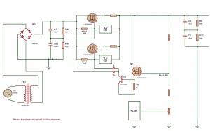
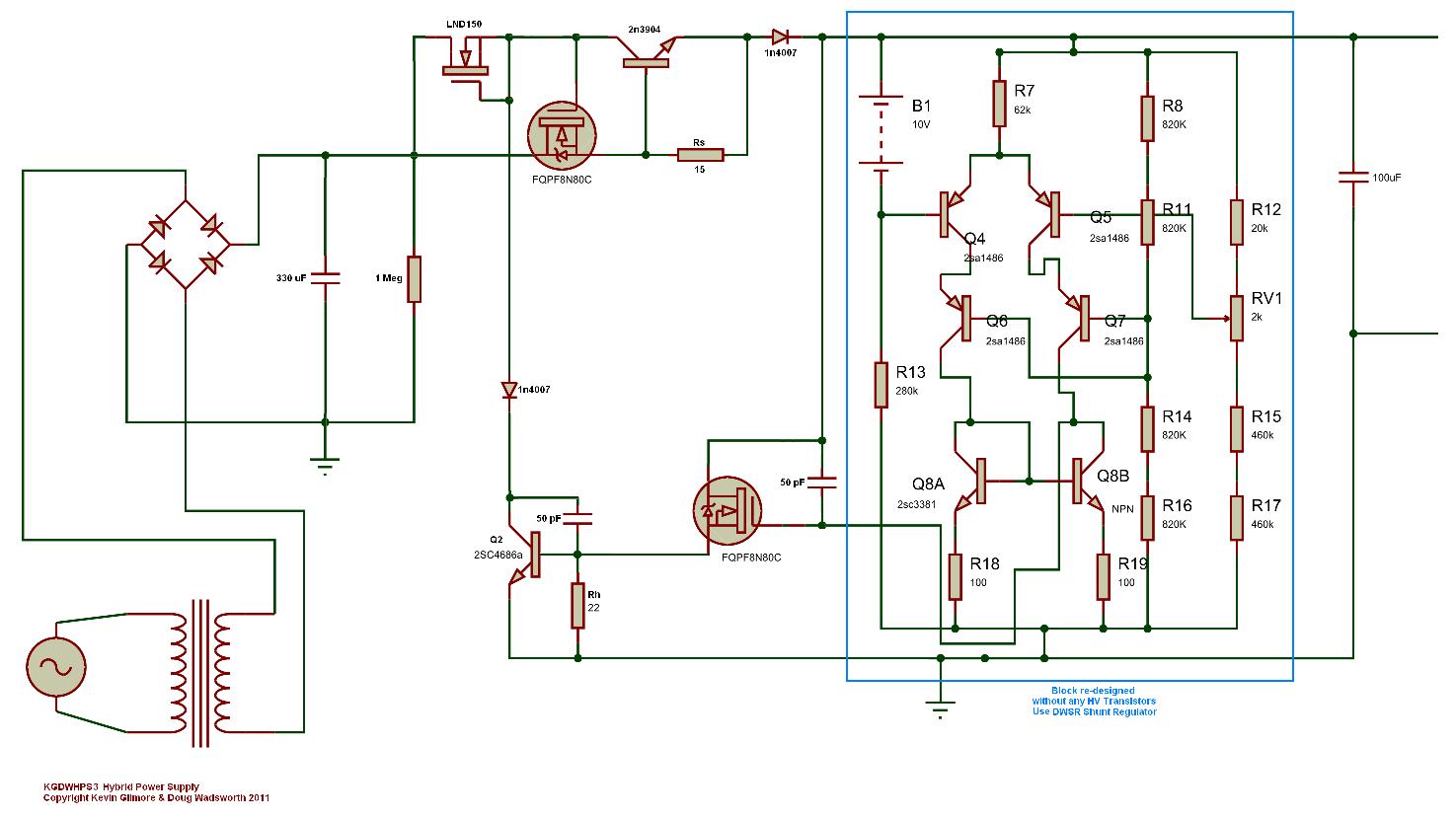
Time for an update on the "kgdwhps3" schematic shown in the previous post (#91). My MOSFETS finally arrived, and I got it on the bench..... Bottom line: It is VERY difficult to make stable with the MOSFET output on the active battery. Using the FET increases the gain of the circuit dramatically, and this is a problem. I cut the gain down by adding a resistor (51K) across the gate and source of the fqpf8N80c, but it still takes lots of capacitance to tame it. So, right now the MOSFET version is a work in progress. MEANWHILE, the bipolar version "kgdwhps2" (post #90) seems to work perfectly, with only 50 pF compensation caps. I've taken it up to 50 mA with 50 uF on the output and it's fine. I haven't measured any noise yet because my "Plexiglas blast shields, Teflon caps, and 5 digit floating noise analyzer" are still on back order! (as recommended by KG for diode noise measurements. ) Regarding the DWSR block that I re-designed, I will have more information very soon. Linear
-
I'm just about to undertake this exact task. Could you share some of your trickery?
-
Attached is "kgdwhps3". I haven't tested this yet, but if it can be made stable, I think it would be the best topology for the new Hybrid PS. (I'll get it on the bench as soon as my fqpf8n80c's arrive from Mouser.) Compared to version 2, the HV NPNs are gone, replaced by the MOSFETs. The ixys10m90s is gone, replaced by the Supertex LND150 (available at Mouser). This is a TO-92 device, off the heatsink. Only the isolated package MOSFETS are on the heatsink, making this easy to build. For higher power and voltage (I'm testing these ideas at 250V @ 50mA), we might add more '8n80c's in parallel, and more LND150's to share to load. Thanks to luvdunhill and the Basaudio guys for suggesting the LND150 (only $0.69!). It's a handy little HV current source. Check it out. Linear Update: Has been tested and has stability problems. See next (#92) post.
-
"Bug Fix" on the ".kgdwhps1". Latest version attached: "kgdwhps2" Added diode in series with series element to avoid reverse current through 2n3904 and Rs. There may (actually, probably will) be additional "fixes". So, don't generate your BOMs just yet! This means you, Justin! (By the way, I really like your chassis work.) Linear
-
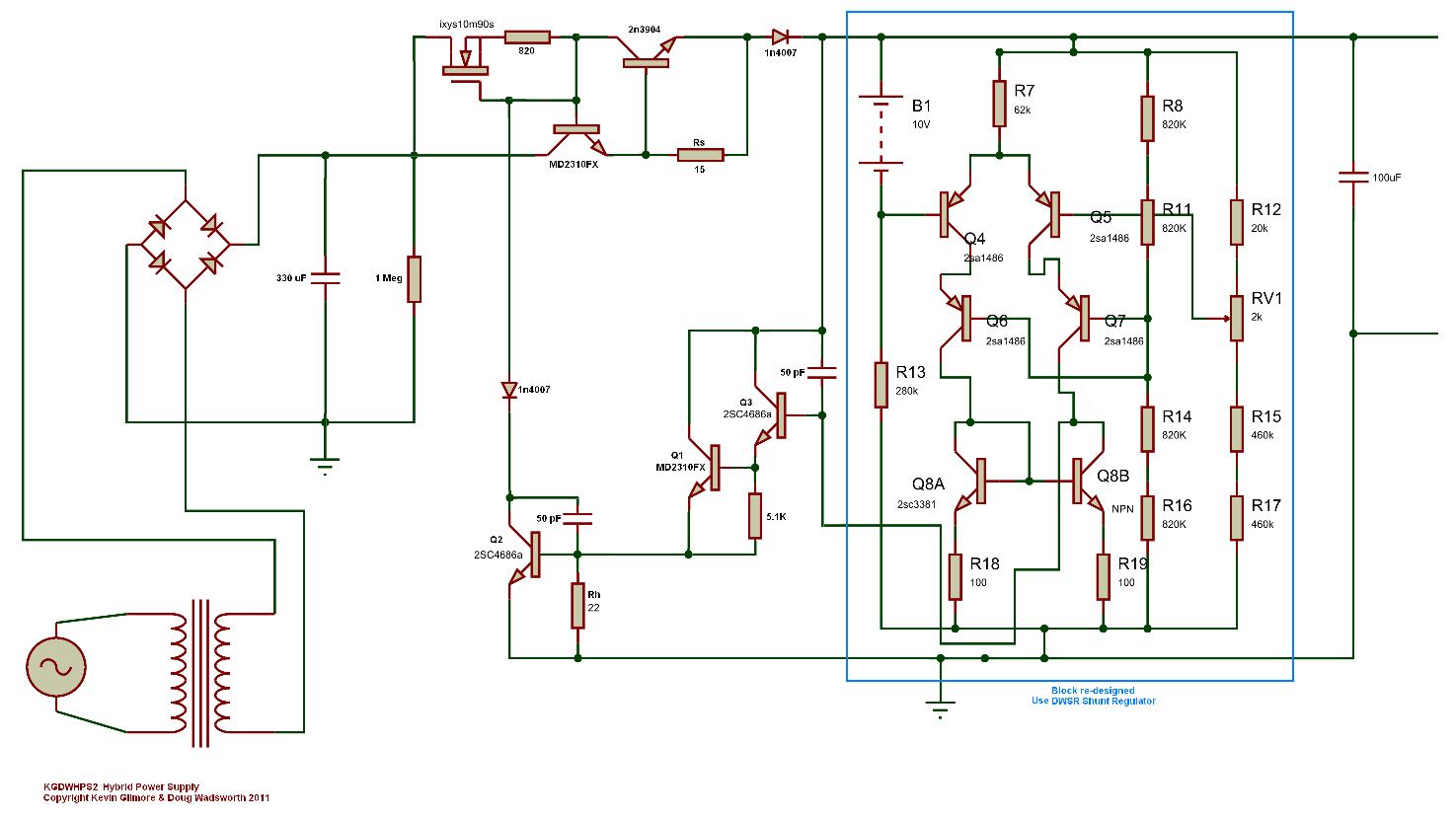
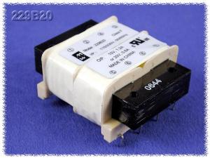
Yes, the Hammond 229 series is a split bobbin. (They call it a "semi-toroid" because it has a few characteristics in common with toroids.) I want to compare the 229 against true toroids, which would have better regulation, lower self-magnetizing current, etc..... In other words, are true toroids that much better that we can rule out using the 299 series?
-
Think I'm going to build a pure shunt PS for my T2 (the one that isn't built yet!) This "kgdwhps" seems to be working really well and the heatsinks really "eat the heat". For transformers, why not use 10 Hammond 229B230's, a 229B56 to get 60V for the 560V rail, and a 229B24 for the +/- 12V. Make it modular, using 12 identical PCBs. The PCB layout could take any of the 229 Series transformers and could then be stuffed to create any voltage. (Triad also second source the 229 Series, as their FP line.) As I said before, this would really spread the heat generated by the transformers around the PS chassis. So what's wrong with using these "semi-toroids"? Let's hear all the advantages of using toriods. Check out what you get for $12 in the pic below.
-
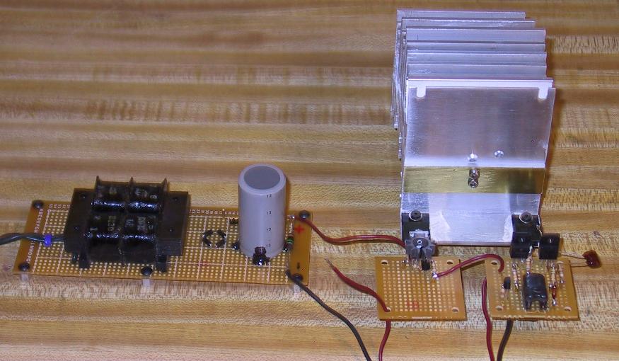
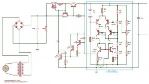
Well, there has been a lot of “talking” on this thread, but not too much bench testing of the ideas. I think that KG is the only one to help out in that area. So, I decided to do my share. I’ve built a breadboard of what I egotistically call the kgdwhps1, and I think that I have some interesting results. The circuit incorporates KG’s hybrid idea (post #19), and my series element (post#24 on the left), but with a bipolar pass device with an ixys FET current source driving its base. (I suggested this exact configuration as “dwpass6” to KG in an email on March 31.) This pass element only has the isolated package MD2310FX on the heatsink Also, I’m using a re-designed version of the “active battery” section (in the blue box) that I call “dwsr”. It doesn’t use any HV transistors (more details on the dwsr later). See the attached schematic. I’ve also attached a photo of my bench setup. This thing is designed to deliver 250V @ 50 mA. It can run as a shunt, hybrid, or series PS, just by changing the values of Rs, and Rh. I’m using a Hammond 229B230 “semi-toroidal” 12VA EI type transformer. These are widely available and only cost about $12. It would take 10 of them to build a full T2 supply, and they could be mounted on the PCB, thereby spreading the transformer heat around. I know they exhibit poor load regulation (20%), but the regulator can handle that. Tell me again why I should order custom toroids? Unfortunately, my ixys diodes are on order. I thought I had some 1n4937 (200ns) diodes around here somewhere, but I can’t find them. So, I’m using “double O seven’s”. I’m not sure how bad (or good) the initial switching noise is with this arrangement (compared to DSEP12-12B’s and a toroid). Comments are welcome (see posts #82, 83, and 84). RESULTS It works! I had to put 50 pF caps across the CB junctions of Q2, and Q1/Q3, to stabilize and set a dominant pole for the two feedback loops. Once that was done, I tried it with no load, dead short circuit (47 mA) and with a 25 mA load. All OK. Hybrid mode also works fine. Obviously, I need to do much more testing, and probably add a couple of zeners for protection. Could try MOSFETS (eg fqpf8n80c), which would hopefully be stable. Looks like a TL431 (Basaudio style) in the series element is NOT stable with the dual feedback loops (KG’s tested it). I’m probably wasting my time testing noise until I get my ixys diodes, right? HEATSINK I have been looking at the heatsink issue for a while (see DIY T2 Clone thread), and so I decided to try a piece (3” long) of the “super large” one I have. It’s cross-section is 4” x 5” with 19 fins! You can see it in the photo. I ran “kgdwhps1” in shunt mode, pumping 11.2 W into it. The ambient was 74 F, and that 3” piece of heatsink stabilized at 114 F. That means an 18” length could handle 67.2 WATTS! That’s just ONE side of a T2 type chassis, so it’s 134 W for a full chassis. KG, your 150 watt chassis is reality! Stay tuned. More to come. Linear

-
Just to clarify. (I'm a bit foggy today, I guess!) If we built a PS with and EI style transformer connected to a 1n4007 bridge, would it have lower switching noise that a torroid /ultra fast diode setup? (Assuming the same capacitor values, etc)
-
Could you give us a quick (few lines) primer on the trade-offs with diodes and transformers? EI transformers? Are they the standard ones with the E shaped laminated core? Are they better for noise? Why use toroids then? Because of their better regulation and lower losses? What about diodes? Anything special about the DSEP12-12B? Will any fast recovery diode work as well? How do "lousy diodes" help with noise? Should we all be using lousy diodes and EI transformers to minimize noise? I'm confused and need advice from the Doctor! I hope that the Doctor is in!
-
Regarding the basaudio: Run for your lives!!! It has TWO TL431's in it! Sprenger and Wright are infected with 431 fever!!!! Seriously, though, the current source they use is what I suggested in posts #24 and #25. I then added T1 and sent it by email to KG as "dwpass4". HONEST, I had never seen the Basaudio cct before! (So, KG, you did see the T1 current source idea earlier!) Also, as I previously suggested, they use a MOSFET Cascode in their shut regulator element. And I thought that was my original idea . Well, at least mine doesn't need a low voltage supply or an opamp, but those components may make theirs a better shunt (maybe?). Damn, I re-invented their circuit! I HATE IT when that happens! I'll try to be more original in the future! Linear
-
Thanks for your comments, spritzer. Yes, I had already thought about doing a mod on the SRA-14s to give it a balanced input. I even went to a lot of trouble to get complete schematics and a service manual for it (from Japan). Then, when it came time to "put it under the knife", I just couldn't do it! I just couldn't cut the chassis to pieces on a relatively rare bit of Stax history. So, for balanced, I'll have to build a T2! P.S. Actually, the 14s schematic is significantly different than the SRM1 Mk2. For one, it runs on higher voltage rails.......I'll send you a PM with more details. Linear
-
Well.....OK, let's just look at just the part that controls the series element (FET of bipolar): Maida: LM 317H, zener, diode, 4 resistors, 2 caps.... Noise= 180uV TL431 MOSFET Cascode: TL431, zener (not shown), 3 resistors, 1 cap for stability (not shown)....Noise= 35uV Remenber, we are not including the components that implement the hybrid function. (That oscillated with the TL431.) Maida hadn't even THOUGHT of a hybid PS, and as far a I'm aware that is an original idea of KG's. BUT, we are working on ultra low noise PS. We need to close of discussion on 180 uV noise power supplies for now! Maybe later, we can see how cheap and dirty we can get! As I finish writing this, I see that KG has beat me to the punch (again!) and basically posted the same sentiments in the previous post. So YES, let's move on and discuss ultra low noise stuff! Linear
-
Post #20
-
Huh?? It looks like my TL431 MOSFET Cascode idea works way better (35uV noise versus 180 uV noise) and has way fewer parts. Why would anyone even consider Miada?? What am I missing??
-
I have a Wadia 170i that takes the digital output of my ipad/iphone and digitally feeds it into my Wadia 861. The 861 has a totally balanced set of four 24-bit Burr Brown PCM-1704 DACs (2 per channel) that then feed into my "swift current" zero-feedback current conveyor I-V converter (US pat.4,983,930). However, I can't use the balanced output of the 861, because I then go into my Stax SRA14S driver (no balanced input ). If (or more hopefully when) I build a T2, I can then go balanced right to my headphones!
-
:angry: :angry: :angry: :angry: :angry:
-
OK, I woke up this morning and I've recovered from "431 fever"! This thread is what I hoped it would be - raw design in real time! Therefore, please don't go and order parts, ask when PCBs will be available, or otherwise committ to something you see here just minutes after it has been posted. We are just throwing ideas around, and there will be a lot of churn before we get to the perfect solution. Correct that, we will NEVER get to the perfect solution! The best we can hope for is to find a a combination of trade-offs that work to our satisfaction. So, where are we on the path to designing a hybrid power supply? Well, we are trying to combine some of KG's and some of my ideas. Hopefully, the resutl will be a PS that can be a shunt type, a series pass type, or a "hybrid" of the two. Switching between the modes will be as easy as changing two or three resistor values. This is what KG proposed with: http://gilmore.chem....huntregver2.pdf What I hope to add to this, is simpler series and shunt elements that only use isolated package devices, thereby resulting in a very flexible PS, that will be easy to build and inexpensive. We already have a bunch of building blocks, and I think that we can reach our goal by putting them together in the right combination. The '431 building block looks like it is too unstable (too much gain with too many transistors, including SLOW lateral PNPs) to be usable with FAST PS designs, especially those with multiple feedback loops like the Hybrid PS. It might work in a simple pure shunt, or pure series pass topology that would have higher noise. A noisy, but low cost solution? Do we really NEED < 5uV of noise? Anyway, at least while I was under to influance of "431 fever, I was able to demonstrate that it can be used in HV PS design, with a MOSFET Cascode arrangement. Where do we go from here? I'm going to send KG an email and discuss all the building blocks that we have. We will see if we can come up with a working KGDWHPS ( .........Hybrid Power Supply )! Linear P.S. As I'm finishing this post, I see that we have an on-going discussion on the DESIGN thread about ipod release dates!
-
I'm working on a version of the T2 battery that is looking really good. It's essentially the same as Dr. Hayashi's circuit, but turned upside down so that it only needs 1 HV device (FQPF8N80C) and the 2sc3381 are gone! It should drop right in to the kgsshvpower3 schematic and give the better performance KG quotes above. But maybe the TL431 approach would be OK as a low cost, easy-build tradeoff, versus the "flat-out absolute best PS possible" approach. I hope the TL431 current sources work out! Right now, I can't see any other option except the ixsy devices. Maybe the NPN could be used if the TLV431 acts up. We would have a Tc on the current, which would lower the current with increasing temp(~0.5%/degree C). Maybe that would be a good thing (to prevent thermal runaway). By the way, the T2 active loads (with the LED biasing) seem to have this kind of Tc. Has anybody meaured the "standing current" of the T2 over temp? I'll try to get to testing the '431 current sources tonight, but KG will probably beat me with some results! Luvdunhill - Yes, "the really long heat sinks I posted in the original T2 thread". Where did you get them? It wouldn't have been from the land down under, would it? Eh, mate?
-
Good point again, Luvdunhill. I found the following on the web. The pink trace is ONE 9V alkaline battery. (The blue trace is a LM337 PS the guy was boasting about.) Anyway, the battery is about -110 dBV @ 1kHz. Now, 100 batteries in series - 40 dB worse? = -70 dBV? Maybe the noise adds rms, and is not quite that bad, but still, it's not an ultra low noise PS! I've cancelled my bulk order for 500 durcells! Low noise is hard work, but then you all knew that. On the site where I fould the battery noise measurements, it states "TL431's are prone to wild oscillations". So, we will have to see how this 431 mania pans out, once we build these circuits. Maybe my cascode MOSFET will isolate the 431 from the load to some degree. But the MOST inportant question of all. Where did you get those massive vertical fins heatsinks, Luvdunhill??? Linear
-
I've just been getting together a bunch (engineering term: "shit-load") of 9V batteries.......they clip together in series so nicely.......idea........what's the date? March 29? OK, it's 3 or 4 days early, but here goes anyway...... ***************************************************************** BATTERY POWER YOUR T2, KGSSHV, OR KGBH AMPS!!!!!! Don't be tied to that wall plug and that heavy power supply! Get Mobile! Go jogging with your T2 and Stax headphones! Specifications: 500 V supply: 52 batteries (9V) 250 V supply: 26 batteries (9V) T2 users: 6 V car battery (for valve/tube heaters) Battery life @ 50 mA: 7.5 hr PS Regulation: -21% @ 7.5 hr (494V > 390V, 247V > 195V) Price: 500V supply = $208 (duracell batteries)* 250 V supply = $104 (duracell batteries)* * Car battery not included ****************************************************************** April Fool!
-
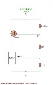
With the TL431 MOSFET Cascode scheme that I posted a few messages back, one can, of course, make a T2 type 740 V active battery. Please see the attached drawing. I don't think you can get much simpler than that, and with a 431A (1%) and 1% resistors, we can hit damn close to 740 V without any adjustment. The accepted Head-Case naming convention for circuits appeals to my ego, so I'm calling this the "DWAB1". (I guess that the 431 MOSFET Cascode shunt regulator is "DWSR1"). Now, there is only one problem with the DWAB1. It won't work as an active battery in the T2! I'm almost sure that it's noise level (220 nV/rt Hz) is way too high. By comparison, the original JFET scheme is about 25 nV/rt Hz. These noise levels come from theory, so I'm going to measure them experimently. (Forget Spice simulation - the macro model for the TL431 almost certainly doesn't have accurate noise parameters. You would have to model the 431's complete schematic at a transistor level.) Let's see: I've got a breadboard of the original T2 active battery, got a breadboard of my DWAB1, got a distortion / noise analyzer, so just hook them up to a power supply.......wait a minute, that has to be an ultra low noise PS, at 740 V! I've got it! I'll use eighty-two 9V batteries is series.....which would cost well over $100... If I don't electrocute myself with a 9V battery (actually, 82 of them), or blow up my distortion analyzer, I'll report back. Stay tuned. Linear
-
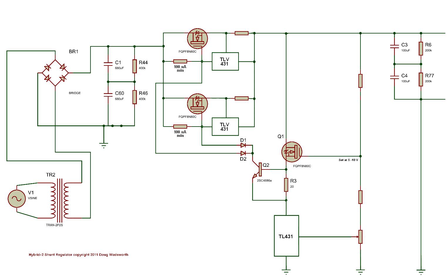
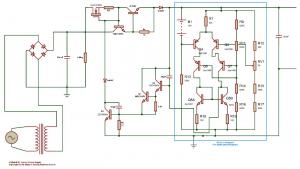
Here it is: Not the world's best PS. But simple, easy to build (all isolated packages), and inexpensive. And it has KG's novel hybrid feature. I threw this togther rather quickly, in the last few hours, so there may be a fatal flaw! Feedback appreciated. Linear