Linear
-
Posts
44 -
Joined
-
Last visited
Content Type
Profiles
Forums
Events
Everything posted by Linear
-
Discussion on the design of the T2 & other circuitry
Linear replied to kevin gilmore's topic in Do It Yourself
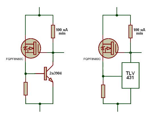
OK, this is the design thread, right? Anything goes! So let's go hog-wild with 431's, and replace the series pass devices with something in an isolated case. Here's what I came up with. Note the use of the TLV431 (it's the TL431's baby brother). It can regulate at 100 uA (versus 1 mA), and that saves us power in the bias resistor. The NPN version might be OK, but has the Vbe Tc. Why not use more 431's !
-
Discussion on the design of the T2 & other circuitry
Linear replied to kevin gilmore's topic in Do It Yourself
It mignt need a cap (eg 0.01 uF) across the cathode and ref. (See Texas Instrument's data sheet, figure19.) Or perhaps the Linear Technology version, LT1431, which has a compensation pin (see pg 8 of their DS). For most amps, we probably don't need the world's best PS, just something that's reasonable good, and simple and cheap to build. Hell, with TL431's, it will be way better than the original T2 PS! (My apologies, Dr Hayashi. Your father probably cut the budget for the T2 PS after you used up most of the project time getting the amp section virtually perfect!). -
Discussion on the design of the T2 & other circuitry
Linear replied to kevin gilmore's topic in Do It Yourself
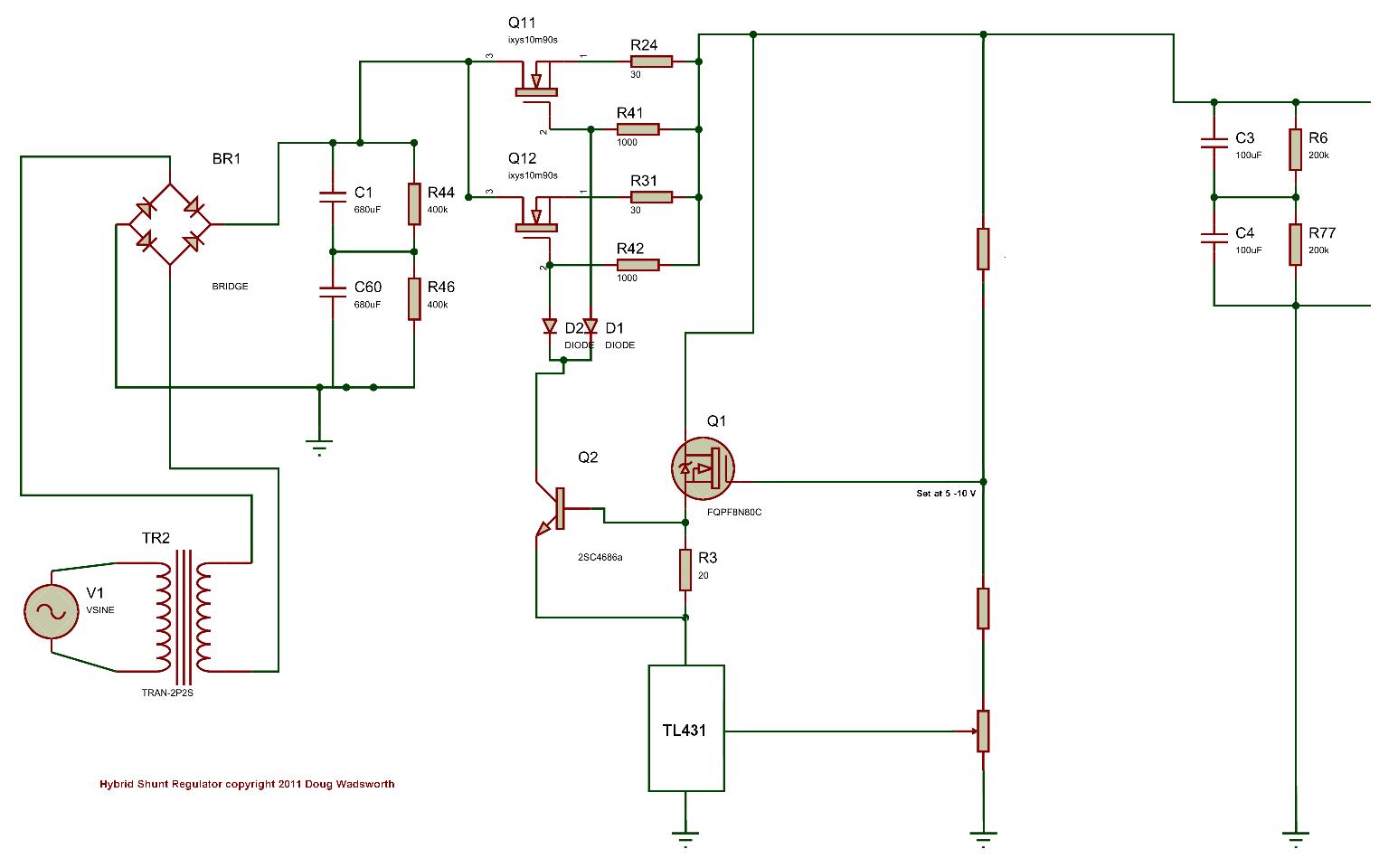
How about this..........
-
Discussion on the design of the T2 & other circuitry
Linear replied to kevin gilmore's topic in Do It Yourself
Everything in the servo circuit is relatively inexpensive and available, except for those 2sc3381's! That's why I looked long and hard to see if they were really necessary. Apart from the cost, it's still probably a good idea for them to go - I think they are going to get the "last time buy" notice very soon, if they haven't already. (Maybe bdent is selling NOS). Anyone out there brave enough to try the cascode mod in their T2? But you do so at your own risk! -
Discussion on the design of the T2 & other circuitry
Linear replied to kevin gilmore's topic in Do It Yourself
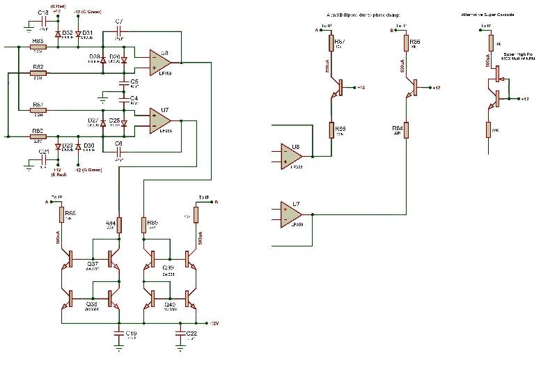
Thanks for running the sim, KG. It was on my "to do" list, but right now I'm testing heat sinks and doing sims on the active battery. (I think that I may have really got somewhere with the battery .....eliminated the 2sc3381 and more.....stay tuned.) The 3381's are only 80V, which is probably why there is a 10K in series with the mirror collector (to drop 5 more volts and protection). We have almost 24 volts LESS across the transistors, but there is a downside to this. Is everyone SURE we still have enough HEADROOM? Of course, KG is right - Put a hv NPN in for maximum safety! Regarding thermal stability, Luvdunhill, I think that the cascode (off the +12 V rail) is better. The output of the servo opamps is a voltage, converted to a current with the 22K resistors (R84 & R85). There are 2 Vbe in series with these resistors in the original version, and only 1 with the cascode. (We can match the original by adding a diode in series with the cascode, if this additional Tc has some magic effect. ) And now the BIG QUESTION: Who will volunteer to try this out in his T2? Linear -
Discussion on the design of the T2 & other circuitry
Linear replied to kevin gilmore's topic in Do It Yourself
Good point, Luvdunhill. But that was then and this is now! Now, Bdent want $7.66 for the 2sc3381 (anyone found a better price?) and you need FOUR of them to make the simple cascode current mirrors used on the servos of the t2! You can buy all the HV NPNs you need for the t2 at that price! But, in keeping with the "design" theme of this thread, I submit, with the utmost respect and admiration for Dr. Hayashi, that it would be completely out of character for him to use up 3381s just because they were cheap and available. The design of the t2 is concise and elegant. I believe that he had a good technical reason for using that topology. Comments? -
Discussion on the design of the T2 & other circuitry
Linear replied to kevin gilmore's topic in Do It Yourself
Hello everyone, I thought that I would get things going on this "design discussion" thread with an interesting little bit of the t2 circuitry. Firstly, I must say that I'm very impressed with the circuitry of the T2. It's just so elegant in it's symmetry and it's use of valves or transistors, wherever they offer the best performance advantage. The dedication lettering that KG put on the PCB is most appropriate! However, I can't understand why Dr. Hayashi did the servo output in the way he did. He bounced the output current off the -12 V rail, using expensive (and hard to get) matched transistors. Why??? There seems to be enough headroon to use the + 12 V rail as a cascode point, making everything much simpler. Please see my attached drawing. So what am I missing? I may be re-laying out the PCB of the t2, so anythng that we can thoroughly check out, that makes it less costly and easier to build, but that DOES NOT change the sonic characteristics of this classic product, will be considered. I've got some (hopefully) interesting ideas on the Active Battery, so "don't touch your dial" Stay tuned to this thread. Bye the way, just to clarify what KG mentioned a message or so back, I did do design work for Wadia (analog "swift current" section of the 861 CD player), but I was a consultant and not an employee of the company. Linear
-
Kerry, Thanks, but KG already PM'd me the dimensions of the brackets. Everything regarding the above mentioned heatsink is for ONE, so it's 10" horizontal for two! There"s also another version with 12 fins, that's 3.73" horz x 2.75" vert for each heatsink. This smaller one wouldn't give KG his 150 watts, but might work well with T2 power levels (~40W). Approximate cost for this smaller one ~$80 each. Linear
-
Gee, things have been quiet here lately! I guess I'm not just late to the party.....the party is over and everyone is listening to their T2s. Anyway, after all his hard work, KG deserves to have this heatsink wish granted. Here is what I should have soon: Material: Aluminum Dimensions: 4" vertical x 5" horizontal Number of fins: 17 Perimeter: 61" Availability: Stock, no minimum order Cost: ~$150 per 18" length I don't have any thermal data yet, but comparing the periphery with other products, the calculations say this thing (18" of it), at 120F, should sink over 150 watts! It will probably be less then that, due to the density of the fins, so as soon as I can, I will measure it myself (hopefully within the next week, or so). KG, I'll send you a 3" sample to try for yourself, after I check it out. Is anyone else out there interested in this for future projects? Maybe the DIY T2 project wore everyone out, both physically and financially! Stay tuned! Linear
-
Could someone tell me the "specs" on the aluminium angle bracket that mounts on the PCBs in the T2? Is it 1" x 1.5" x 1/8" ? The holes are on 1/2" centers, correct? Are they tapped for 4-40 thread? How far are they in from the edge of the angle bracket? Thanks! Linear
-
KG has kindly agreed to host some files that I thought would be of interest . The PDF files are redrawn from KG's large "t2schem" schematic, arranged on 3 pages: IP, OP, and Servo & Battery. This effort was inspired partly as an aid to understanding the circuit, and partly by Craig Sawyers "simplified schematic" diagram. Like Craig's drawing, it seems easier to follow the signal path with this arrangement. The JPG files are an article on the t2 from the May 1995 Japanese magazine "MJ". The only thing in it that I can "read" is the block diagram! Note that the +/- 600 V rails are not accurate, but the components and topology seem OK. It reminds me of Craig's "simplified schematic", which he reposted a few messages back. So, can anyone out there HELP?!! It would be great to have a translation of the text. I know there are several "Head-Case" members who live in Japan - Please HELP us out if you can. Hope that the above files are useful. Linear
-
Could you upload any active battery stuff that you have? I'm working on the battery right now and your thoughts would be helpfull. I'll report my findings in detail a little later, but here are a few preliminary observations: As mentioned a few posts back, the JFET reference was used because it has very low noise. Indeed, RV2 (in series with the JFET) acts as a coarse voltage adjust, while RV1 is a fine adjust, BUT.... RV1 also adjusts(and minimizes) the temperature coefficient of the JFET reference! So, what is the Stax recommended procedure for minimizing this Tc ? Has anyone ever seen an owners (or service) manual with this info? Perhaps the reason that Stax built the original active batteries as "modules" (little daughter PCBs in a heat sink) was so they could put each in an oven, minimize the Tc with RV1, and then install them in the T2? More to come on all this. Linear
-
Yes, that is a real Stax SRM-T2 in my avatar, but I don't have one! I got the photo from a Japanese web site back in 2002. At that time I was lusting after a T2 or a schematic ( so I could build one). I even wrote to Stax in Japan, requesting a schematic, but they very politely declined my request. So, imagine my joy when I discovered this thread, where KG and Spritzer accomplished what I could not! Thanks again guys! I did, however, get a copy a a review of the unit from the May 1995 issue of the Japanese magazine "MJ". That article has a very detailed block diagram of the T2 with the tubes, the 2sk216, and 2sj79 MOSFETs shown. The text, of course, is in Japanese, but I'll try to post it on the group here. Perhaps one of our members could translate it. Linear
-
Since I'm going to be using 2sc4686a devices in my T2, the active battery circuit will have to be modified. So, I thought that I'd take a look at re-designing it with a "modern" reference. The original JFET reference seemed cumbersome and "out of date". Well, it looks like Dr. Hayashi had a very good reason for using the JFET. Here's the deal: Obviously, minimizing noise in the T2 is very important, and since the active batteries are in the signal path, their noise contribution can be critical. The reference voltage on the base of Q16 (in the battery circuit) is about 6.6 V, so it gets multiplied up by over 100X to generate 740 V. Therefore, the noise component in this 6.6 V also is amplified by 100X. So, let's compare the various reference types in nV/(root Hz) @ 10Hz: Bandgap (eg TL431): 220 Burried Zener (eg LM329): 100 JFET Idss current: 16 22K resistor: 20 It looks like the JFET and resistor combination (25 nV/rt Hz when summed, I think) is 4X to 10X better noise-wise, versus "modern" technology! I'll check this out on the bench, but all I can say for now is "hats off" to Dr. Hayashi! Linear
-
Well, I may be late to the party, but I've decided to take the plunge and build a T2! I've just ordered some 2sc4686a parts from Mouser for what seemed to be a good price ($0.82 ea). Can any of you give me a lead on where I can get 2sa1486, 2sj79, 2sk216, and 2sc3381 at a better price than B+D? They seem to be expensive ($2.82 for a 4896a!). I guess that I'm too late for "group buy" PCBs, heat sinks, etc, so I'll do the best I can on my own. T2 fever is very contagious! Best regards, Linear
-
Thanks, Craig, for posting the T2 diagram. After looking at this drawing, a question comes to mind: Is the beautiful sound of the T2 determined almost completely by this topology, the 4 tubes, and the 6 MOSFETs? How critical are the current sources? In other words, if we built the current sources and the 740v battery using "modern" (ie different) components, would it sound significantly different? Comments anyone?
-
Craig, Your link, quoted below, seems to be broken. Perhaps it's because you moved to a new ISP? Could you post a new link where I could look at your "block diagram" of the T2? Thanks for your help. Best regards, Linear
-
Hello everyone, I'm new here, and I have spent the last few days reading this thread. It certainly was interesting! My congratulations to all involved in this project, especially KG and Spritzer for starting it all, and making the first unit. I think that Craig Sawyer also deserves special mention. His perseverance in solving the "defective (low hfe) 2sc3675" problem was inspiring! Hopefully, I will be able to make some small contribution to all that has gone before, now that I am a member of Head Case. Best regards to all, Linear
-
Hello Quad, I'm a little late to the party (by over a year!), but I do have a lot of technical information on the SRA14S and other Stax products. If you are still interested, let me know. Best regards, Linear