JensH
Members
-
Joined
-
Last visited
-
My package arrived as well. Thanks.
-
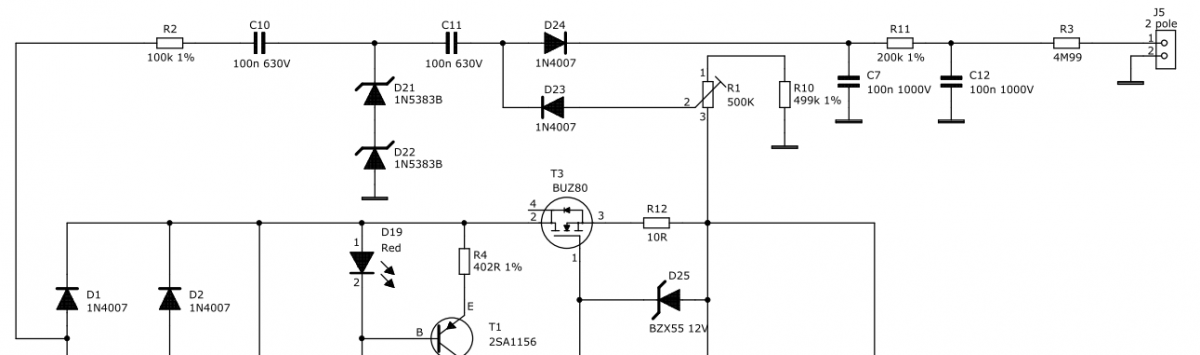
@Remolon I made the bias generator like this to reduce the output voltage variation caused by variations in the mains voltage. The zeners D21 and D22 are 150V zeners.

-
I would also be interested in some 1486, 4686, 1968.
-
Err, which part of it would you like to change? I hope you mean the work part
-
Rodrigo, The connectors arrived today. They look good and they fit the headphone connector perfectly. Thanks. Jens
-
Great, then we agree Interesting links by the way.
-
The 250V DC does seem to be a printing error. On the other hand, it would be very impressive, if they could handle 250V DC and 3A. Even if the peak voltage of the 250V AC is of course higher, switching 250V DC is much tougher, due to arcing. See e.g. http://www.jenningst.../acdcswtc.shtml If you look at the data sheet of a relay, e.g. this one http://www.conrad.de...214211&ref=list under "Documents and Downloads" you will find a huge difference between the DC and AC performance.
-
The switches only seem to be rated for 24V 50mA. Fine for a PC ON/OFF button, but they should not be used for mains applications. This seems to be better suited: http://www.conrad.de...NG-BL/?ref=reco But of course, they are not black. They do have a lot of different models though. You can of course also find them on the UK version of Conrad, but I could not get the direct link to work on the UK page. http://www1.conrad-uk.com
-
@PICaudio Could you please send me a PM. I don't seem to be able to do so. Probably because I am new here. JensH
-
I just got a KGSS (not the HV variant) up and running recently. It is based on my own PCB layouts for the amps and the PSU. The first amp board I assembled I fitted with the current sources based on the IXTP01H100D. The temperature drift seemed to be fairly large, so for the second board I went back to the original KGSS configuration using resistors. I expected this to have much less temperature drift and that also seems to be the case. So at the moment I am running both boards with the resistors instead of the current sources for the third stage. Looking at the data sheet for the IXTP01H100D I guess quite a lot of temperature drift is to be expected, since the drain current, for a given VGS, changes a lot from 25 degrees to 100 degrees. I would expect a current source based on the 2SA1968 to be less temperature dependent. Unfortunately I don’t have any 2SA1968, so I am not able to test that at the moment. Has anyone here compared the two solutions and have an opinion on this? My amp PCB is actually prepared for mounting either resistors or a current source, based on the 2SA1968 (which I don’t have!), but not the current source based on the IXTP01H100D (which I have!), so I had to mount it in a less than optimum way. I used 1.2k resistors for the IXYS current sources.
-
I'd be interested in 1 of the 5 pin connectors including pins if possible.