Aive
Returning Member
-
Joined
-
Last visited
Everything posted by Aive
-
Awesome thanks for the info - I'm always looking out for good internal cabling/wiring. Sick of using the canare stuff, that screen is a mofo.
-
Very professional build! Just wondering, what cabling did you use there - I can't make it out from the printing on the sheath.
-
Which automatic centre punch did you end up getting? I'm keen for one
-
What nice tools you end up getting? (Always keen to learn how to do metal work better) I bought a Ryobi drill press from Bunnings, it is inaccurate like fck, gotta do a lot of manual compensation to get holes positioned... I think a simple centre punch will go a long way to drilling better
-
Try these: Version 1 Version 1a Version 2
-
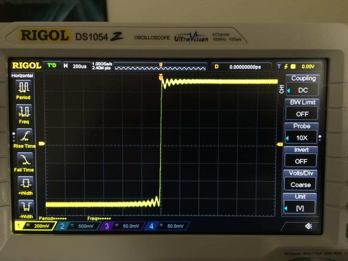
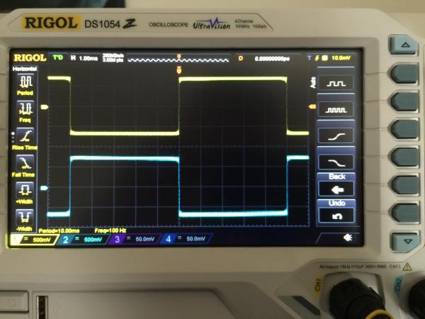
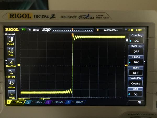
Update: I may be an idiot. I presumed that what was being output from the DAC would be correct. But that's not the case - the issue is with the DAC. CH1 = Amp output, CH2 = DAC output. DAC output is the same ripple BS with it disconnected from any load. What a fool I am to accuse the KG amp! Now to fuck around with the DAC to see wtf is going on.......

-
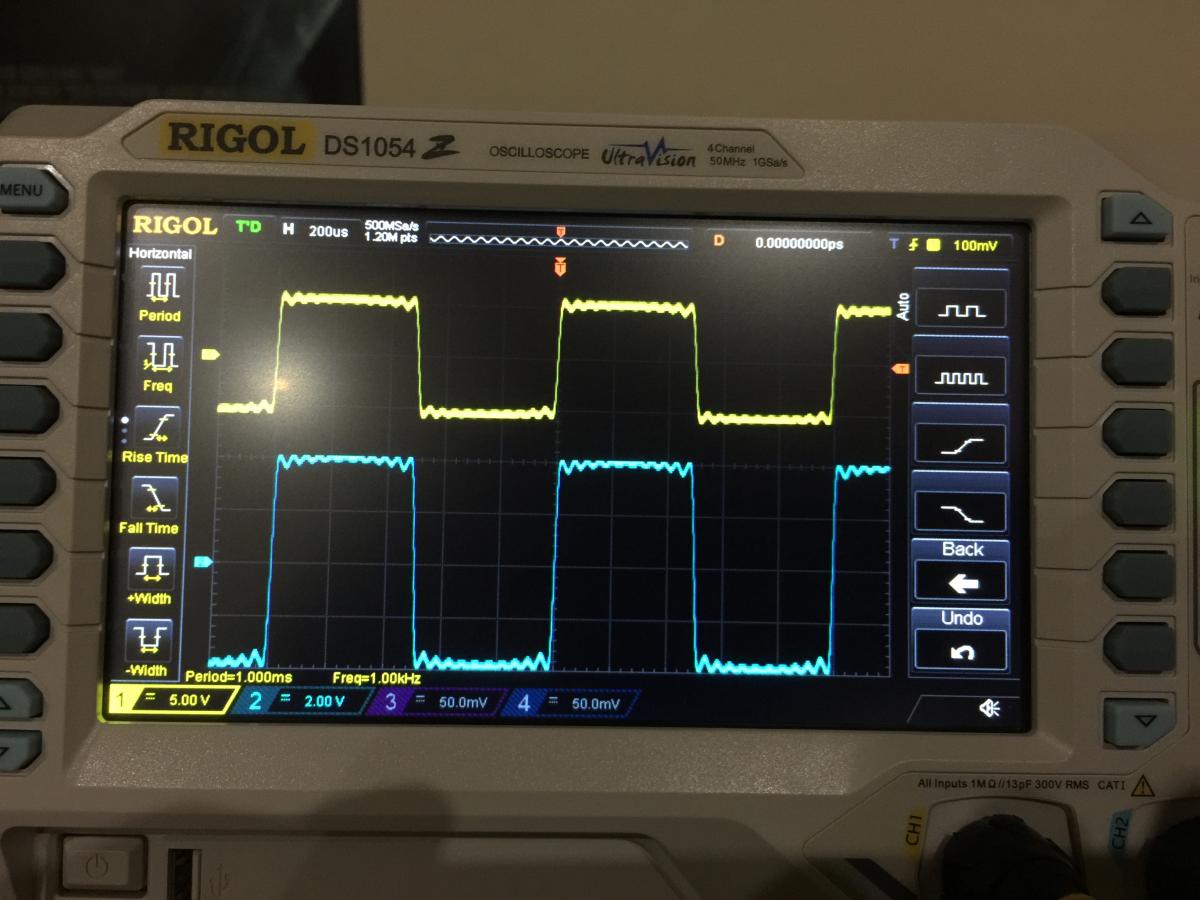
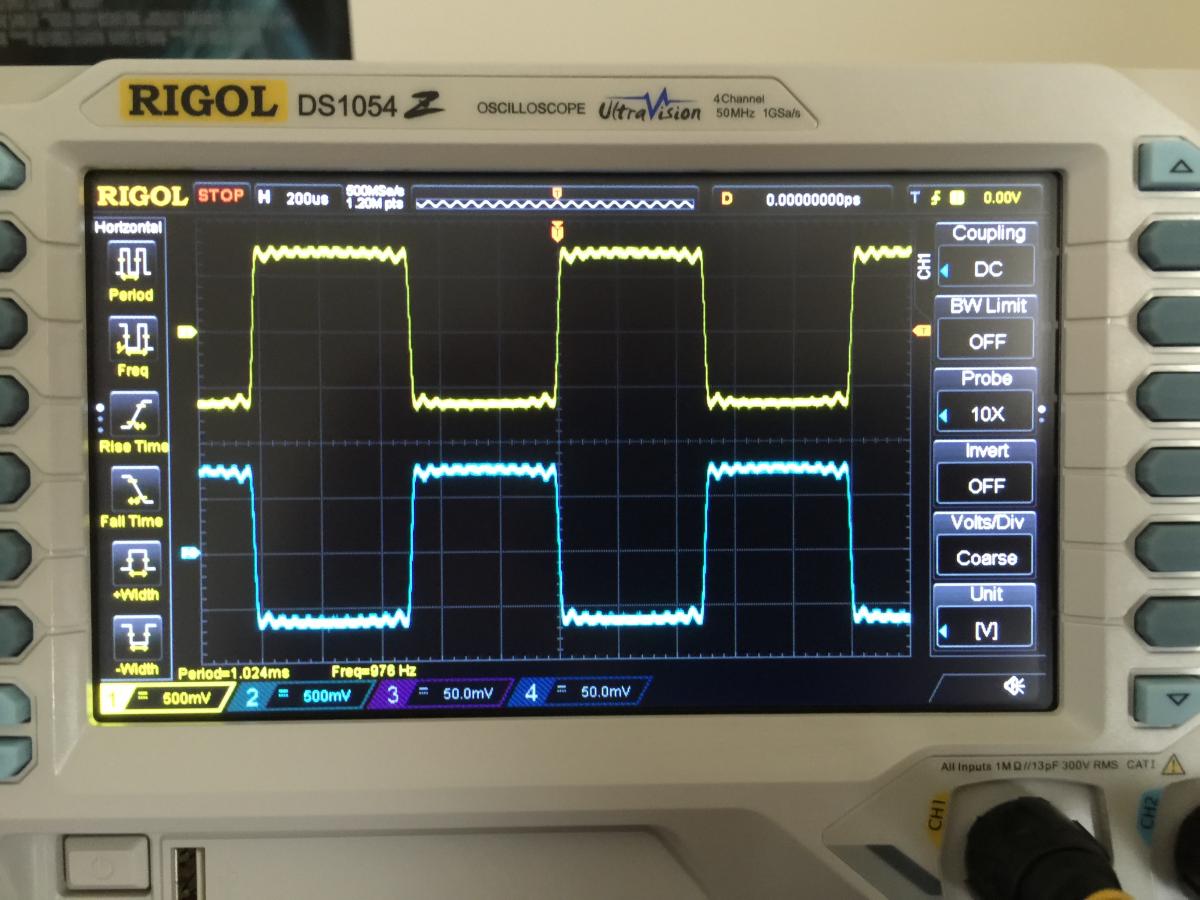
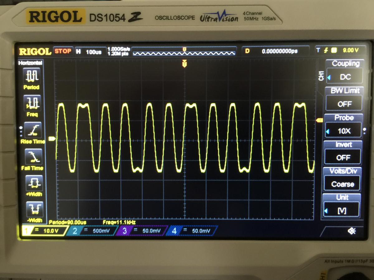
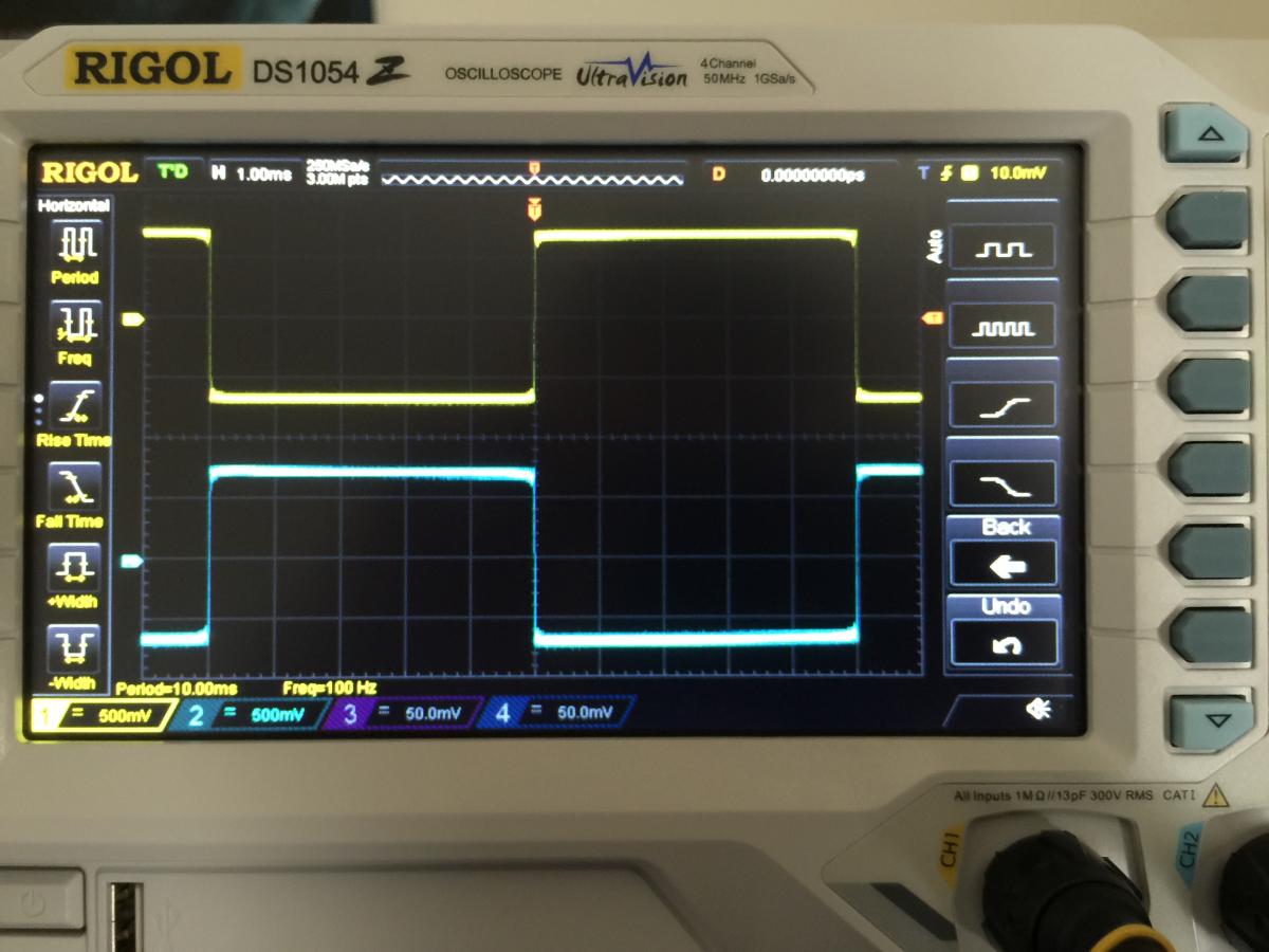
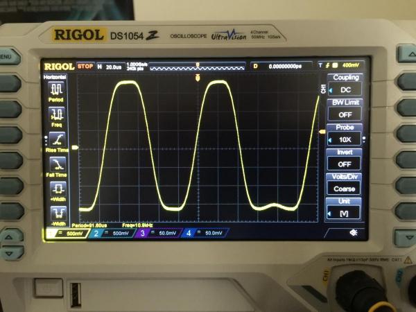
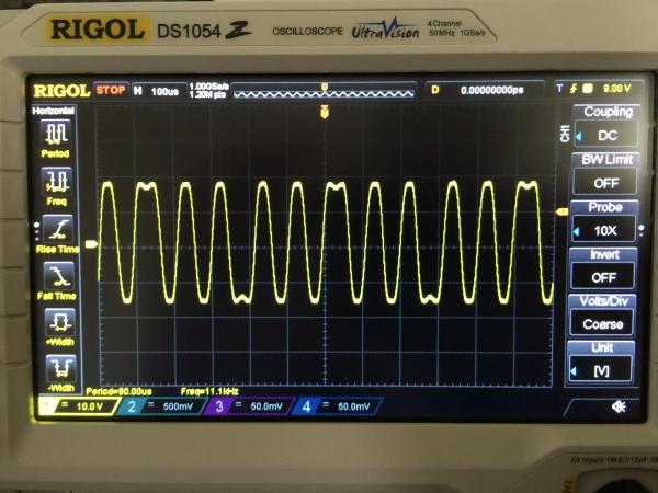
So I got my CRO finally I'm seeing some weird behaviour on output of my SuSy Dynahi with square waves. Getting some serious ripple on the positive and negative sections of wave duty cycles at lower frequencies, and losing the 'squareness' completely at higher frequencies. Suspect low-pass filtering frequency is too low presently and I'm filtering out important harmonics... this is particularly evident with the 10 kHz wave photos below. Measurement parameters: - Square waves generated via Matlab. Also downloaded some square wave .wav files from the net for comparison. - Outputted via my MBP -> DAC (AGD M7, USB) -> balanced output into SuSy Dynahi - Amp is set at default gain as per original silkscreen, haven't changed anything since I built it. Photos below show left channel, + (yellow) and - (blue) signals. Sorry for the bad quality of the photos - I really should hook the CRO up to my PC... 1khz square wave: 100hz square: 100 hz square (zoomed): 10khz square: 10khz square (zoomed ): Any ideas for how to improve/fix this? Will be a fun problem to solve, gives me something to do again Edit: Should also mention, measurements taken with no load on output of amp board.

-
Hey joamat, your boards look fantastic. What method do you use to etch those? Printer toner transfer?
-
What's the reason for 5 pf? Just out of interest, keen to learn..
-
Hey G600, what size compensation capacitor (in feedback circuit) did you end up with for your 55 kohm feedback resistors for 11 gain? 3 pf or 5 pf?
-
Thanks Kevin, might avoid a gain of 2 then... Dumb question, you previously posted some capacitor values for a gain of 11 (55 k feedback resistor) - I'm assuming we want as much bandwidth as possible through the amp, so 3 pf would be the recommended value here? I think gain of 11 is where I'll start with my tuning...
-
Hey Kevin, do you think it's practical to drop the gain to 2 (balanced gain of 4) by changing R52/R56 to 10 k? Do you know what would be the associated capacitor values if this is practical?
-
I really can't get over how good the bass is with this amp, don't feel the same love on my GS-X although the treble is smoother on it. Ended up ordering a Rigol 1054Z DSO for more tweaking pleasure Ppl looking for a DSO/CRO should look into this relatively new unit from Rigol. Can option hack it to unlock upgrades too... New Rigol DS1054Z oscilloscope
-
lol, think I can stick with 2 pf caps for half gain?
-
Hey KG, thanks for the response. If I just want to halve the gain do I use 100k resistors? What would be the associated capacitance values? Thanks Edit: ordering bits in OZ is a pain in the ass so I'm including a few component options in my list... Edit2: Man this compensation capacitor theory is voodoo, been trying to learn about it all night - most optimal solutions = get a CRO and wave form generator and trial >< dayum. I should've stolen one from my uni days :/ Will be getting a rigol next year though, gonna be so handy for this diy goodness.
-
Would this be appropriate KG? Is there a calculation for gain and frequency response? Edit: if I change the resistors to lower gain do I also have to change the caps? Thought the roll off frequency is fixed based on cap size... I'm not sure if it's 5V RMS or PP it doesn't say on the DAC's website :/
-
My DAC specs says output impedance of 10 ohms and voltage of 5V. Should I reduce the gain?
-
Yeh I tend to notice grain/etchiness on certain tracks in the treble region - will need to do a comparative test with my GS-X MK2. Maybe I haven't biased it effectively resulting in additional distortion...
-
Hmm, I seem to notice some grain/etch on certain tracks - any ideas? I really need to get a CRO to see what distortion I've got, maybe I've biased it wrong...
-
I got my pcb from birgir/spritzer. Cheap and fast shipping totally worth it.
-
Hmm I bought my sand from bdent and Spencer of fetaudio - do you know which devices may be mismatched? I'm guessing its the 2sk389 or 2sa1349... Edit: after looking at the schematic I am not sure what it could be... I can easily even up the mirror (so that all output transistors are bias equally) so it's not as though there is imbalance in the circuit. It's just that when I do, my DC offset is at 270mV between O+ and -. Edit edit: it sounds really good as is I might just leave it for the time being and re look at it when I get a CRO
-
Hey fish, I built the toshiba version of the boards - I got there in the end. I spent a lot of time trying to figure out the circuit and make logical progress instead of trial and error. Stared at that schematic a looooong time lol. What you explained sounds very similar to what I did - but one of my channels took a lot of pot adjustment and one side of the mirror circuit had to be ~100 mv more biased than the other to drop the offset. Unsure why - any ideas? Might have more analysis of the circuit and see which component(s) I could swap out to change that... Any ideas? G600 - I'm using an Alps 4-gang 10 kohm resistor I got from "familygate" on ebay. I built boards as per the silkscreen details, so the default gain (but again, I built v4 toshiba sand version of the dynahi balanced). I've mounted all boards onto MDF now - much less worried about something shorting or falling over and blowing my ears out It is a seriously sweet amp, going to be my primary amp going forward. One thing though, music at low volumes seems "mushy", lack of power, clarity, separation, could that be to do with the low input impedance?
-
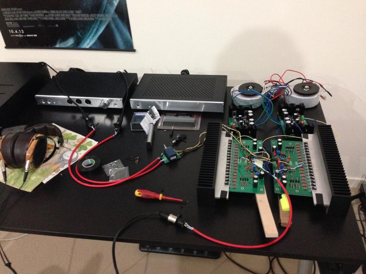
Finally, it makes music! Like my current board supports - PCB brush and highlighter plus some random box... I must've spent at least 8 hours biasing/offsetting one channel due to serious mismatch issues I guess, the other channel took half an hour to do lol >< I am very fortunate to have big ass heatsinks so I had plenty of bias headroom to play with. It sounds pretty sweet through my LCD3s. My audio memory is terrible so I can't make any legit comments comparing it to my GS-X mk2, but the music sounds great, the bass is powerful, I don't hear any noise and don't detect any obvious flaws. Thanks KG for the design, LK for the boards, Spritzer for the advice and pot board and peeps here for posting their knowledge Now to spend the next year of my life on the case...

-
hehe thanks for the assurance Oddly enough, I can zero the offset without the servo, but it gets worst when I install the servo..... offset hovers around 10 mV, think I'll just leave it ><
-
Yeh they're sigma22's. I think I got there - I was trying to do this at around midnight last night, bad idea. Thanks for listening to my whinging lol. I sat down with schematic this afternoon, thought about it and went through the process properly (I'm supposed to be an EE ffs ><).. I set main bias resistors to max and then decreased them evenly till I got around the 0.75 V point for the output transistor resistor branches. I then tweaked the other two trimpots in turn to reduce offset and while measuring across the 5 k resistors in the FET circuit to keep them relatively even - I sacrificed this for better offset though. Got there in the end, little bit of imbalance here and there around the circuit but overall offset close to 0. Had to retweak again with OPA445 installed, but all good - hope it holds... Question though - I did a multimeter measurement for offset upon initial power on and it spikes to 30 mV (could be more but that's what the meter picks up) - will this damage headphones if they are plugged in on power on?