Aive
Returning Member
-
Joined
-
Last visited
Everything posted by Aive
-
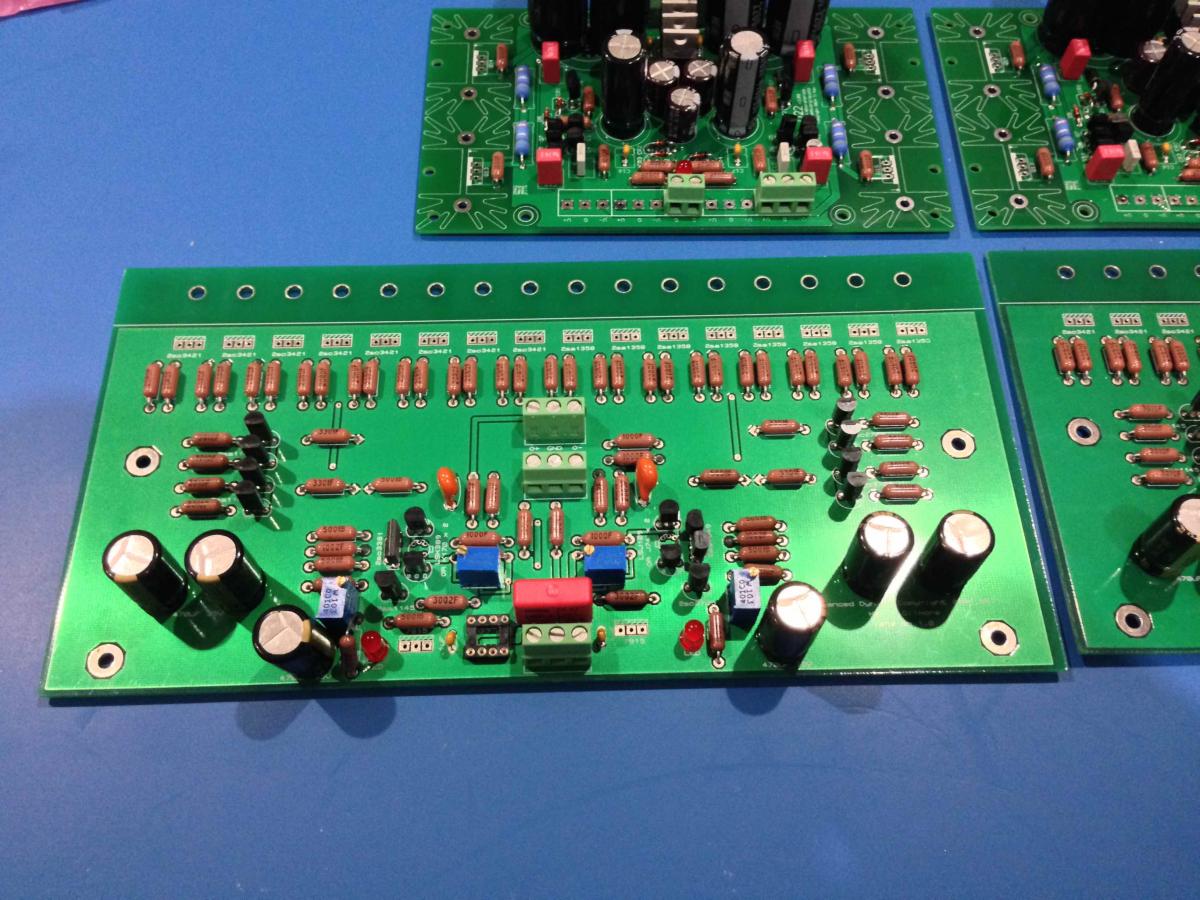
I need help I have one bal. dynahi channel setup and am now in the process of dialing in the bias and dropping the offset. So dialing in the bias is easy enough, I tweak RV1 and RV2 evenly till I get minimum of 0.75 mV on the resistors on the output transistor circuits. Oddly though, I get varying voltages in the output branch resistors of ~100 mV. I suspect this is fine so long as they're all biased > 0.75 mV for Class A? Now with the bias dialed in, I measure 300 mV of DC between O+ and O-. How do I get rid of this? I can reduce the offset via RV3 and RV4 - but it means dialing one of these in very far in one direction, is this ok? I was dialling these in a rather ad-hoc fashion but am thinking of desoldering these trimpots, resetting to mid-point and starting again in a more systematic fashion.... Thanks in advance!
-
Cool thanks john
-
Hey John, just noticed you're in Sydney! Very slick build - just wondering, where'd you source the rest of the panels (front, bottom, top)? I'm in Brissie.
-
Well, I've done as much as I can until my tap arrives and I buy my drill press Gotta clean the boards too at some point. Exciting Oh thanks to everyone so far for all the solid information!
-
Ahh ok, I only checked the Mouser spec page.
-
Those LEDs you listed are 2.2 v forward voltage drop.... I think you need the 1.7 V variant if it's anything like the dynahi?
-
Thanks boss! You got a drill press for all your metal work stuff?
-
Hey Spritzer, what does your FET and transistor test/matching circuit look like? Am I fine just going off AMB's examples - Device matching? There are so many different test circuit suggestions >< Gonna try to get a matched FET quad from FETaudio too
-
For the dynahi build I'm doing I'm basing BOM off the silkscreen as I think that detail takes precedent. Also in re to the 0.1 uf caps I went with ceramic disc type based on other BOMs I've seen for KG amps. MLCC type is probably fine though as I've seen that specd before too. Can't remember what I specd for the 1uf...
-
Awesome thanks Kevin. Will need to get boards made of those if I seriously stuff up LKs boards >< Also is my bias/offset setup understanding above correct?
-
Thanks Kevin
-
That's awesome. Must be good feeling to finish a project
-
Ok, I've been doing a little bit of research while I wait for all my bits to arrive Just wanted to run my understanding/theory re setup of this amp past the guru's here just to check if I'm on the right track (I am trying my best to figure things out as much possible without asking dumb/annoying questions ).... I know I'll be repeating a lot of what is already on the interwebs but am just including it for completeness: Reference circuit: http://gilmore.chem.northwestern.edu/dynahibal1.pdf RV3: Compensate mis-match between 2SK170 pair (2SK389) RV4: Compensate mis-match between 2SJ74 pair (2SJ109) RV3 Procedure: Start wiper at mid-point -> measure voltage across R7 and R8 -> adjust RV3 till voltage equal = equal collector current flowing through pair RV4 Procedure: As above, but match voltage across R13 and R14 And this is where my theory understanding falls apart a little... Increase R1 & R4 to 680 ohms. Original 500 ohm values may be too low resulting in too high bias in drive transistors. RV1/RV2: Compensate imbalance between components in (not sure of the term)'positive' and 'negative' sections of balanced circuit (LEDs, CCS transistors Q1, Q2, drive transistors) => Minimise DC offset and set bias of drive transistors. Iterative process of adjustment -> check bias (resistor voltages) -> check DC offset -> adjustment. RV1 Bias Procedure: Start wiper at max, 10 k point -> reduce RV1 till close as possible to >= 0.75 V (minimise heat dissipation) across R24-R27 and R37-R40 resistors = correct bias through drive transistors Q15-Q18, Q27-Q30. RV2 Bias Procedure: As above but measure voltages across R28-R31 and R41-R44 resistors = correct bias through drive transistors Q19-Q22, Q31-Q34. DC Offset: Ideally, drive transistors are matched to provide equal current through each leg (at least matched set in positive section, matched set in negative section of circuit) however, if individual drive transistors are not matched, will end up with varying voltages across resistors = sum to a DC offset in output. To compensate for DC offset, reduce RV1 (continue reducing resistance since we just reduced resistance to reach min. bias level above) and see if offset approaches 0 V. If not reset RV1 position and reduce RV2 resistance. Whole reason for wanting to understand the process is I don't think I'll get much success from matching of components so I'll probably need to balance amp manually - I just don't have the quantities which seem to be required to make decent sets.... Hopefully the above is sensical, and thanks for all the help, appreciate all the input and advice I've received from you folk since I joined Oh and Kevin, is dynahibal4.zip the latest and greatest design based on Toshiba sand?
-
I think as a rough estimate, it'd be the same version board as what Steve and Vortex initially received. But I can wait till I receive the PCBs and respond. Yeh I complete understand why you switched away from the toshiba parts, deep down inside I was hoping LKs boards were your newer design so I could save some cash buy buying the newer, cheaper bits Will post a response when I know more.... Thanks KG!
-
Hey Kevin, Would it be possible to get a copy of the silkscreen (or gerber) for the balanced dyanhi PCB design from Lil Knight's first GB (lol it's rather specific) - alternatively, your latest balanced dynahi design based on Toshiba sand? I've ordered a set of boards from LK, and I've been told that they use Toshiba components, which makes me think it's from his first GB batch and not later batches which were for your revised design using THAT340 chips... Gerber's would be great as I can then look at getting replacement PCBs made if I make a mistake on LK's boards >< A schematic for the original design was linked here: http://gilmore.chem.northwestern.edu/dynahiver2a.pdf - but I don't think it captures everything. E.g. it seems to be missing 2 x trim pots for example. And an alleged layout was linked here http://gilmore.chem.northwestern.edu/dynahibal.jpg but I think that's a preliminary version and the GB boards were different based on posts: - - (which has photos of a dynahi board that look different to the layout picture - again, layout only details 2 x trim pots and photos show 4 per board) I'm basically trying to put together a BOM for the passive components so I can get an order underway (I live in Australia and want to try and get the order as complete as possible so I don't have to pay additional shipping fees - yes I'm cheap!). I started with Vortex's BOM linked in the first post but I don't think it's 100% accurate based on info above. I've been trying to follow the dynahi journey of others as best I can, rolling in changes/fixes into my BOM as I continue my research, but I just can't find an exact schematic/board layout. Sorry for the verbose post. Thanks for your help Kevin, appreciate it
-
Thanks for the confirmation Spritzer I'll buy a few and see if I can get a good match going heh
-
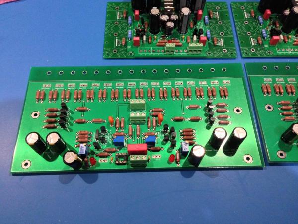
Hello all, Managed to source balanced dynahi and PSU boards from Lil Knight and am in the process of orderings components for the boards. Long journey ahead. Just wanted to confirm: Are 2 x 2sa970's a direct replacement for 1 x 2sa1349 on the amp PCB? I'm quite sure it is based on the datasheet, reading through this forum and googling, but just wanted to quadruple check And matching isn't a necessity with this amp is it? I'll be getting BL versions from bdent.com, think I saw a comment from spritzer saying something to the effect of 'its ok'... Thanks for your help
-
Just wanted to join in and say thanks as well. I'm going through a mid-life crisis phase of my life, and as part of this, I'm starting to get serious about DIY audio At this stage, I'm in the early phases of planning to construct a balanced dynahi amp (attempting to source some PCBs at this point, might have to fabricate some myself from the gerber's you've made available and checking to make sure I can get all the antiquated components) - got a long journey ahead, but this place has provided a great starting point.