willsw
-
Posts
12 -
Joined
-
Last visited
willsw's Achievements
Member (2/6)
4
Reputation
-
I watched a factory tour of some company that made DACs, maybe it was PS Audio, and they had a wall of shame by the repair bench that featured one that had been caked in a similar damping paint. Applying a sealant over a PCB that hasn't been cleaned is also a great way to make it much more likely that it will fail much sooner. Maybe this guy is a rogue employee from Acoustic Revive: Probably because of their glossy casework, seeing the inside of a Viva amplifier for the first time was the worst kind of surprising.
-
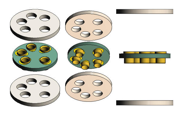
So far I've been using PCBway for all of my printing, since I already order PCBs from them regularly. JLC seems like it would also be good, probably equivalent in most ways, like their PCB production. The one minor downside to PCBway is that the lead times for printed parts can be less reliable and a few extra days for completion is not uncommon. I've been wanting to try some US-based services, especially for larger orders, but so far have only tried Xometry once, when there was a time-sensitive need. They were good, and more expensive. The biggest disadvantage to using printing services instead of having a machine is that I can't really dial things in like this, though if I talked to the engineer running the machine they could probably give useful advice. I've started to use hexagonal or octagonal holes where possible to avoid this. I've also had to drill out some 2mm holes to use a batch of parts. Another tolerance thing I've run into, at least with resin parts and without having control over the part orientation on the bed, is that flat surfaces can sometimes become convex, which is a problem if the part needs to sit flush. To avoid this I'll usually add some kind of concavity to the surface so that only the edges make contact. @JoaMat's construction is pretty much what I've been thinking about, since it makes pin removal much easier than Neutrik's rotate-to-release (which did not work for me when I tried with a loose contact) or using a tool. I've also been thinking about a version that could be laser-cut or more simply CNC'd, if the plug piece was sliced into two pieces. You wouldn't get the nice flush panel mounting though. Circular connector contacts would be interesting to try, like this Amphenol AT62-210-1231-1820, though the ebay collet-style are going to be cheaper than most of those. I was also thinking about a PCB-mount socket, using Mill-Max 0321 or Preci-Dip 16008-83-4010 sockets, which are equivalent. A PCB with no copper could act as insulator and improve mechanical strength. Here's a quick render, without the necessary flange with mounting holes or traces to attachment points. A flex-rigid PCB socket could be cool in production, with the flex material potentially allowing some amount of "floating" contact behavior and also eliminating a few solder joints between the amp's output and the socket.

-
What were you testing with the different pin hole diameters? Did you use the threaded collet-style socket? I'd like to try printing some sockets to work with these Neutrik HA-3FXX crimp contacts, but I don't have a 3D printer. When I finish the file I'll upload it for someone else to try.
-
Panasonic makes great film caps. I've used many different types for many applications. When used for audio coupling, my experience has been that higher voltage ratings tend to sound better. Look for caps designed for high frequency, high voltage, high current circuits (like PFC or resonant power circuits) and you'll usually find good construction that has nothing objectionable to audio. The ECWFD series you linked has copper-clad steel leads. I tend to look for copper leads on principle, though most datasheets will just say "wire leads". According to a list I made many years ago, Panasonic series ECWH(V), ECWH(C), and ECWFG have copper leads. Series ECWF(L), ECWF(A), ECQUA have copper or copper-clad leads. I think the leads are more likely to be copper with higher voltage ratings. The only slightly annoying thing about the Panasonic caps is that they'll sometimes throw out a non-standard lead spacing (17.5mm, why?), but I don't think that will matter to most people.
- 1 reply
-
- 1
-

-
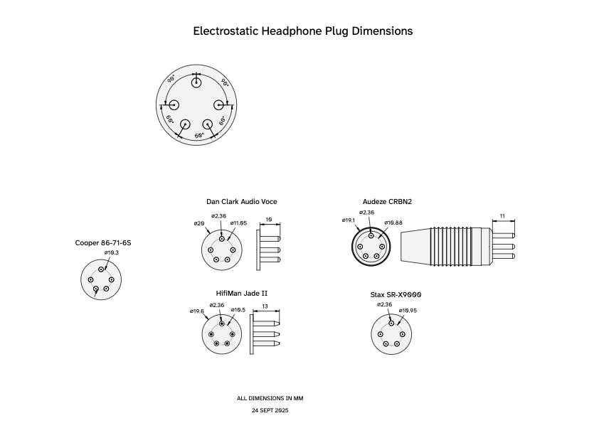
Thank you for the additional information. I've updated the drawing in the first post: - Corrected my pin diameter measurement after using a digital caliper instead of an analog one - Confirmed that the Dan Clark Audio dimensions are accurate for the original Voce - Added the Audeze CRBN2 dimensions - Added the SR-X9000 dimensions from simmcomm The CRBN2 pins were slightly splayed similar to how simmcomm describes his Stax pins. In both cases this is probably from using sockets designed around KG's drawing. The Hifiman pins, being even smaller in circle diameter, are visibly worn on the inner surfaces. Eventually I'll get around to contacting Stax and some others to hopefully get official drawings.
-
I enjoy thinking about different ways to accomplish the often-overlapping electromechanical goals of audio devices. Every few years I get to considering electrostatic headphone connectors, and every time I end up finding the same collection of vintage part numbers, shared experiences, and a few useful drawings that can be put together to probably lead to a functional socket or plug, if you want to make one yourself. I appreciate and have used that information, and now I'd like to consolidate it and create some actual specifications to help anyone trying to make a plug or socket. The most useful thing to start with would be plug specs. Pin diameter, length, pin circle diameter, and housing outer diameter, in case you want to make a recessed socket. Here's a drawing of a plug I got from Dan Clark (I can't guarantee that it's the same as his current production plugs) and a plug from the Hifiman Jade II. If it would be useful I could make a complete model of both plugs and share the STEP files. Next week I'll be able to add the dimensions for the Audeze CRBN2. Eventually I should be able to measure some Stax plugs. Found partial catalogs for Cooper and Amphenol 78-S6S socket and 86-71-6S/91MPM-6S plugs, but neither specified pin diameter. Standard pin diameter seems to be .093" or .094" (2.36-2.38mm), the same size as a 3-pin XLR contact or an octal tube socket pin, or a Size 12 circular connector contact. There is a standard housing layout for #12 contacts that matches the position of a 6-pin Stax plug, arrangement 16-6 or 17-6, but I haven't been able to find any documentation of the pin circle diameter. Neutrik also makes a crimp socket contact, HA-3FXX. The threaded socket most commonly used for electrostatic jacks and tube sockets (like this, or these) is good and conceptually simpler to design a housing for, but I would love to find a design guide or get some advice on the right way to make a hole for circular connector contacts or that Neutrik contact. They're probably not easy cavities to machine from a single piece of material, but 3D printing is useful, and I saw some mil-spec circular connectors that appeared to use stacked layers. Standard pin circle diameter is . . . something between the .406" (10.31mm) in the Cooper catalog and the .435" (11.05mm) of Kevin Gilmore's socket drawing. The Hifiman plug was closer to the Cooper at ~10.5mm. The Dan Clark plug seemed to match up perfectly with the KG drawing. My estimate of this Viborg socket from their drawing puts it closer to 11mm. If anyone has any dimensions to share I'd be happy to add them to a single reference PDF. Any other useful application information about connectors would be good to include as well, if anyone has had experiences with pins being too long or too short, or pin-to-pin clearance standards, or other things. Cable-related information would also be valuable. EstatPlugDimensions.pdf
-
I was talking about the PS2, though if you ask Cardas it's actually the GRFA PS A, the replacement for the discontinued PS2. They told me this last March, but the website still has the PS2, not the PS A. I did get a sample from Cardas and made a footprint for it, but it's untested. I see now that you were talking about the DBL PRT in an earlier post, which I'm very familiar with. Right-angle connectors are certainly much simpler if you're combining XLR and RCA, and I'd probably go with angled if you didn't have a compelling reason for the vertical mount. To achieve a double row using the right-angle version of the AEC/Vampire RCA you can alternate mounting them staggered on the top and bottom of the board, which would also reduce the potential width of your board, given the need for nut-tightening clearance. Not really an issue with a single pair, though. Because of this issue, many manufacturers just wire solder-cup XLRs to the RCA-holding PCB. Since you're trying to avoid the switch wiring and XLRs are very friendly to solder, this may be the easiest option, and the smaller boards are cheaper too. A note on the board you posted earlier - I'd recommend flipping the schematic symbol or rotating the switch so that all the traces are short and direct. You've got a lot of unnecessary length and an unneeded via. The datasheet for any switch should also tell you the height for spacing needs. If you do find a lower-profile switch that you love, really want vertical mount RCAs, but are willing to have XLRs off-board, there is also this style of RCA, which is probably the best suited for being either PCB-mounted or wired separately. If you look up pictures of Denafrips products, you can see them in action. They actually seem to have transitioned between a few standards of mounting them directly on the board and wiring them to the board.
-
 willsw changed their profile photo
 -
I've always been confused by Vampire Wire and their lack of online presence. I remember a quaint website but it seems like the domain name no longer works. Since I've done a lot of work with this specific RCA, here's the info I have so far, for posterity and reference: They almost certainly had those RCAs made in Taiwan, either by AEC or First Tech, which have different addresses but could also be associated in some way, given that many of their offerings are identical. I've worked with AEC and have had good experiences with their products. I've attached the drawing for their version of this RCA. Center pin is center conductor, off-center pin is ground, the other pins are purely mechanical and not attached to the others. These connectors are usable on the same board as Neutrik vertical-mount XLRs, but you will need to prepare for certain adaptations. I've found a few examples of production components using this connector combination. Kinki Studio has been the most valuable for providing use examples, as they've implemented a few different strategies with both vertical and right-angle versions of these. The first approach is to mount the Neutrik XLR with wider slots in the PCB, so that you can slide the mounting pins through and solder the wider part, allowing a reduction in the height of the XLR. I've done this method and used slots that were 0.75mm x 3.4mm. These seem to work fine. You can cut off the original PCB pin from the XLR. Here's an example of this method. In the bottom right of this image, slightly out of focus, you can see the spacing you'll need for the RCAs. A 5mm spacer measured from the black housing seems to work, or a 7mm LED spacer that will slide over the signal pins, to accommodate the recess. The stability pin will just reach the board and can be soldered to provide a bit of support. I haven't tried the second approach, but if you're willing to give up the stability pins you may be able to use the XLR's normal pins. Here's an example from Kinki, and here's a shot kinda showing the increased spacing. I think I remember that the Cardas vertical RCAs were a better length for matching the XLRs, but price is a thing and you'll also need to measure it yourself before making any boards, as their online documentation is not guaranteed to be accurate. p_151229_05831 (5).pdf
-
Thanks for letting me know about those pins. I'll let you know what happens with the project.
-
That's useful, thank you. I have gone through a few threads found here and around about making the jack, but the part that will probably be most difficult and requiring measurement is machining the female pins. I suppose it could be cheaper to inversely determine things by using a plug as the model.
-
I'm considering getting some custom Stax-style jacks made and thinking that the most reliable way would be to get the measurements from an actual Stax jack. There are some cheap 5-pin electret amps out there that I wouldn't mind paying to possibly destroy, so I'm wondering: is that socket exactly the same as the Pro 5-pin?
-
For anyone in the DC area, after Axpona this weekend we'll have them indefinitely at LTA/Urban HiFi, and I'll bring them to any meets in the area. Post-Axpona update: Dan needed the set for shows and will replace it with an earlier revision that is still useful to us in development, but I'll need to check about whether they would be a reliable demo pair.