Ulfar4
-
Posts
13 -
Joined
-
Last visited
Recent Profile Visitors
1,477 profile views


Ulfar4's Achievements
Member (2/6)
0
Reputation
-
Does anyone know where to buy 2sk216? I need two pieces, there are plenty of them on ebay but I bet that they will all be fake ones. Or if anyone have two pieces?
-
The power supply rails are ok as it measures around +-230V without load.
-
Thanks, it must be it. Because then would also not work current source for the jfet. Yeah, my bad, of course to the source, same as for those amps as you say. Anyway, I updated schematic in first post. Now I desoldered all 2sk216 and two of them are dead. Those mosfets were on one side of the right channel. I will disconnect amplifier part from power supply and see if the rails measure ok. Any other ideas what else should be wrong?
-
Hello all, I have this unit, but it stopped working so I opened it up. It seems that in right channel are shorted mosfets on output stage. But LEDs are not lit on both channel so I need to check it more. I started drawing schematic from the board. Since this is only one sided pcb, it was easy. But there is one thing I don't really understand. It is the cascode pair of 2SA1699. It should be that emitter is connected to the drain of the 2sj109 and output is at collector. But there it is connected differently. Or there is something I don't see. If we look on the board, there is drain of the 2sj109 and it is connected to the base of 2sa1699 according to datasheet. Maybe someone has full schematic of this board or can point me out for what is wrong. There are full pictures of this board.
-
Thanks, now it works like charm.
-
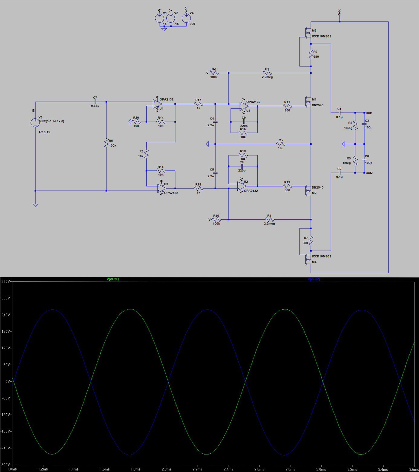
Hi, I wanted to simulate srm-1 amplifier in LTSPICE to understand how it is working. But I'm not able to make it work. Maybe it is something trivial, which I do not see right now. But I'm running out of ideas. If someone point me to the problem, I'll be happy. Thanks for help. asc.zip

-
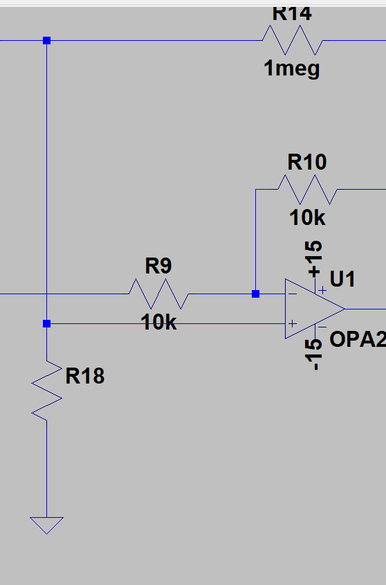
Thanks, so with feedback it should look like this. I also changed R3/C2 fo CCS. Or in this case it is better to run it without feedback?
-
 Ulfar4 changed their profile photo
 -
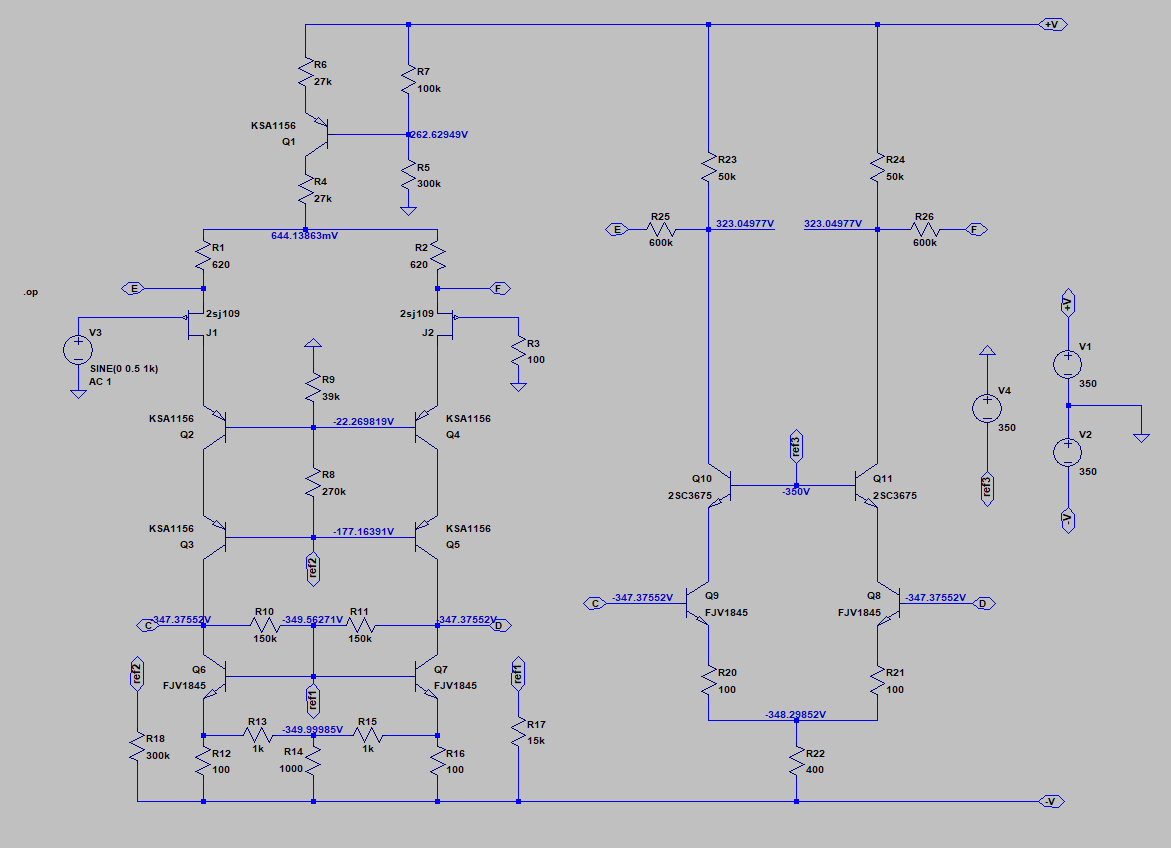
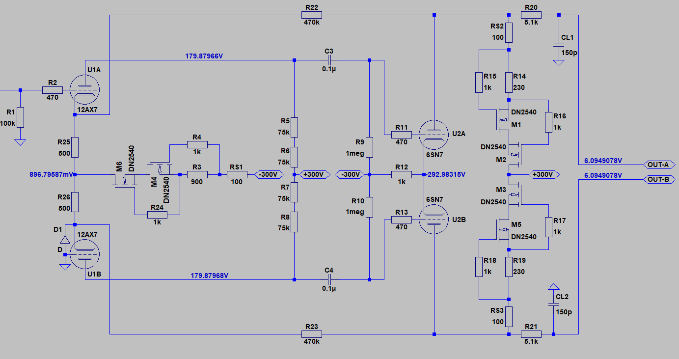
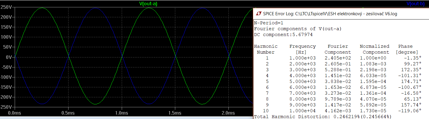
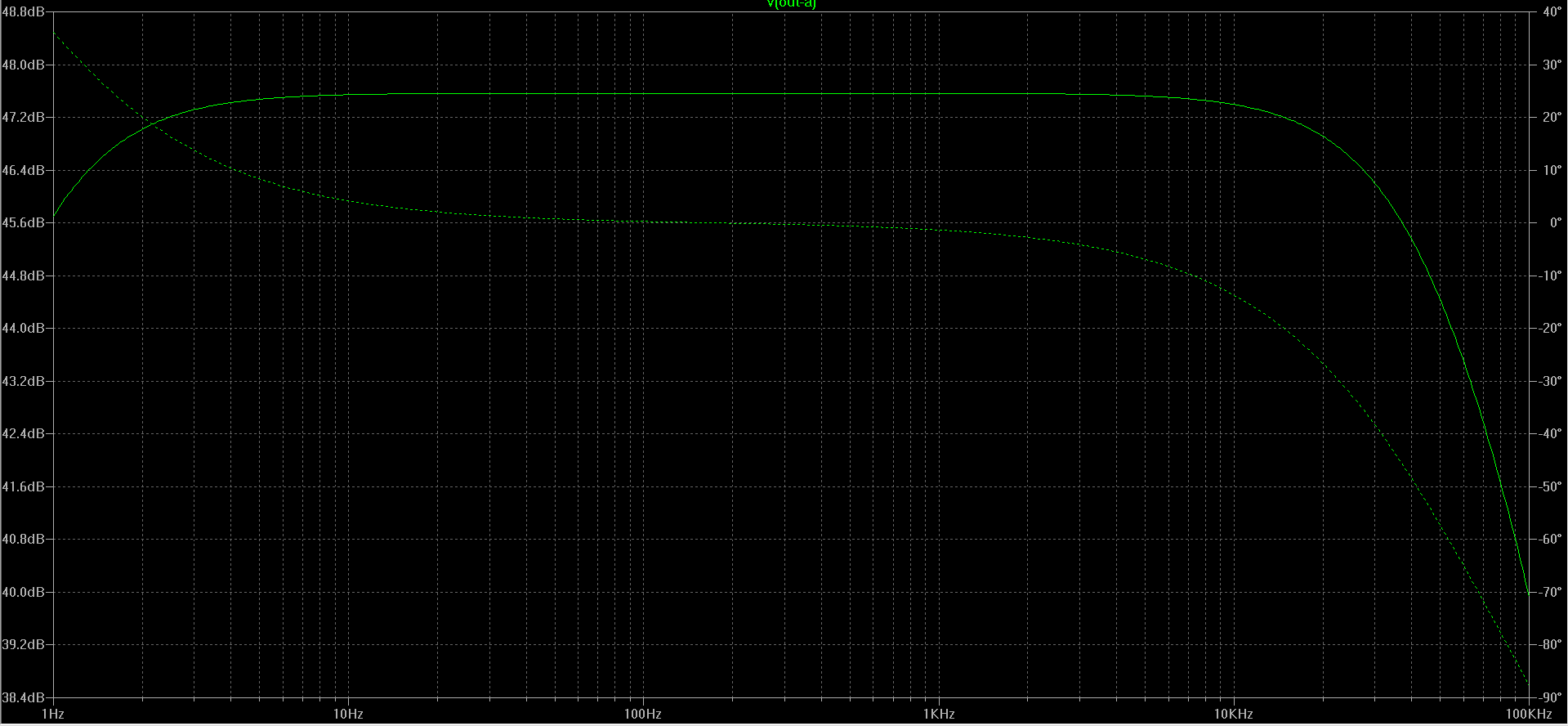
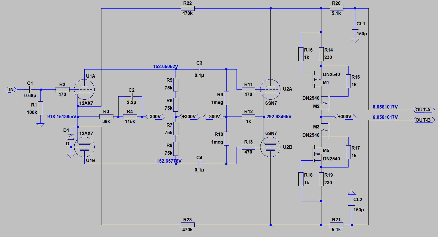
Hi, I know there are many schematics like this but this aims to be a very cheap amplifier for the estats and it should be better than the SRD boxes. The power supply for tube has +-300 V and there will be four windings on transformer for heaters. I know I can not trust the simulation so I think it will have a maximum output voltage around 500 V peak to peak with some luck, probably less. I took the CSS from SRX+, so credit goes to JimL. Output current is set to 6mA per one output. So 12mA per channel. I added small feedback to stabilize it with 470k resistors. My goal is to make a small cheap amplifier. Voltage output is rather small than other amps but I will not use it with something like SR-009 or simmilar. THD is approximately 0.4% at 460Vp-p. But I do not know how much are those models reliable, so it can be very different in the real world. Fr of course drops around 20kHz like all these amplifiers (Triology .....). Tubes I intend to use are: ECC83 6SN7 Thanks for any comments and sorry for my english if there is some mistakes.
-
Thanks, it helped me alot.
-
OK, so I have to put there resistor like this?
-
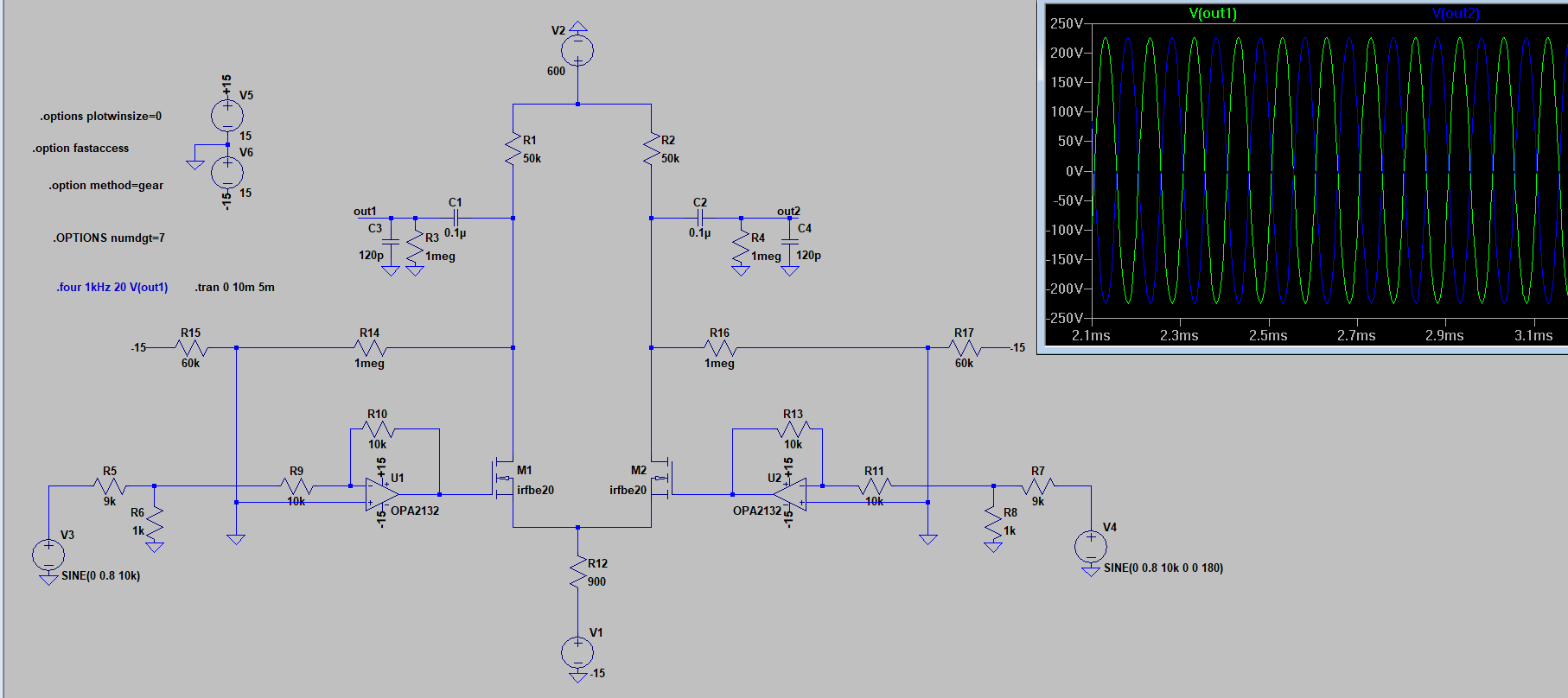
I was trying to fix it. I put negative voltage on the feedback as you said. I cannot find bsp125 as to220, but i found irfbe20 which is up to 800V. I hope this time I have done it right. Only problem is that I cannot put css in there without ruining output. With those 50k resistors the simulation worked. Anyway, how much voltage swing is actualy needed for esl headphones? Something like stax sr207 for expample.
-
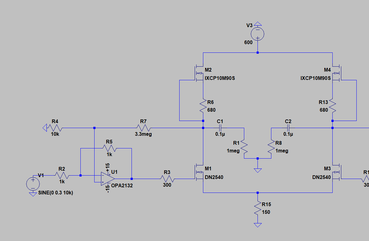
I was assuming that the 600V supply will split to 300V per side. So I put in there 10m90s as css. Is my thoughts wrong then? I redraw the feedback little bit acording to hev70. If I am understanding correctly, the feedback is there for setting the offset? Yes, it will be easier. But for me, it's a lot more expensive than building something like that. Besides transistors I have all parts so it will be inexpensive. I will sure look at it, but I wanted to avoid tubes. But I believe that it can sound very well. This is only for fun so I could experiment with headphones.
-
Hello everyone, I am going to build a DIY esl headphone but first I need some amplifier. I really do not want something fantastic, just to try out the headphones and then build something better. My inspiration was from John Broskie Tubecad schematic and head-fi forum. My question is will it play? And if not, what to change? Thanks for your help.