


Rinat
-
Posts
75 -
Joined
-
Last visited
Content Type
Profiles
Forums
Events
Posts posted by Rinat
-
-
On 3/29/2023 at 12:09 AM, jokerman777 said:
Hi, I'm slowly sourcing parts for a T2 build and wondering if 2SA1627 will be a fine replacement for the 2SA1486s that are not mounting to the heatsinks (those I will just use KSA1156)? Seems to have mostly the same ratings other than only 1W of maximum dissipation, would make my life easier if it works comparing to using the SMD STN9360...
Thanks! 🙂
I use 2SA1413 (It is the same transistor in a different package).
-
 1
1
-
-
3 hours ago, simmconn said:
The so-called 'active battery' is a shunt regulator IMHO. I would recommend that you simulate any circuit changes for performance (shunt impedance) and stability.
Yea and they often use such a capacitor to decrease output impedance at high frequencies if a voltage divider uses high resistance and it forms RC chain with control transistor's capacitance: C3 in this scheme for example.
3 hours ago, simmconn said:Using 2.2nF compensation cap would significantly increase the loop gain in the mid- to high-audio frequency range and reduce the output impedance as you have observed, but also make the stability worse.
Since the active battery is part of the signal chain, I would rather shoot for flat impedance across the audio range and as small phase shift (group delay) as possible. I'm not sure what your test gig looks like.
1. I thought about the stability, but we don't see any instability or generation during the measurements.
2. Currently the impedance of the AB is not flat at all. In my measurements it increases almost twice from 100 HZ to 1 kHZ.
But I understand your point, thanks. I will try to simulate or even measure a phase shift too.
3. I will make a simulation after insuring that all the component in my library has proper models including parasitic capacitances. Do you have spice models for transistors?
But the final check is always a measurement 🙂 . I will probably also change the test circuit by changing the R5 resistor with 2SK216 transistor and modulating it by AC signal.
4 hours ago, simmconn said:On the other hand, the LT1021 due to its high-ish operating current requirement, does not necessarily bring much gain to the overall performance of the active battery compared to the LED strings.
Why does the operating current matters here ? We always feed the battery by the same 5mA current.
-
 1
1
-
-
3 hours ago, simmconn said:
I'm not sure what your test gig looks like.

-
1
-
-
1 hour ago, jamesmking said:
The area around Q17p is more problematic due to an extra track which results in one tracking having to be rerouted.
🤔
Hmmm, did not think about tracing, because am doing AB as a separate small board.
-
1 hour ago, jamesmking said:
Nice work, its always good to see progress and new ideas for the T2.
Thank you! The idea is also not mine, but my friend's.
1 hour ago, jamesmking said:Just to clarify. I did not design the mostly modern T2 battery. I simply created a series of posts on my build and posted my modified gerbers and updated and clarified schematics.
Oh, I didn't know this. Anyway this is great work, that made my labor much easier. Thanks!
Now I am building 2 amps:
1. The original T2 with as less changes as possible.
2. The possibly better version of T2. In this version all the upgrades would be made not to use modern parts where it is possible but only to improve the amp. For example STN9360 is better in many places than old and rare 2SA1486 and vice-versa for the FJPF2145 and 2SC3675 pair.
And this amp is based on the scheme that you posted here. Thank you very much for that. And of course thanks to all the authors of ideas!
1 hour ago, jamesmking said:Your battery looks promising. If I could suggest, PTFE caps of sufficient voltage are quite large and not easily available new. I think it would be possible to find a place on the amp pcb for 1KV film caps e.g. wima. I would also be interested in the effect on the existing mostly modern T2 battery if just the cap is fitted - since such a modification would be very cost effective for existing mostly modern T2s. If the cap mod is shown to be stable and reliable I would be happy to update my existing post to include it in the schematic as a option and update the gerbers to make a place for adding the cap.
Dmitry used the PTFE cap only because we have only 0.001 uF(too small) and 0.047 uF(too much IMHO) PP caps, and to make a funny photo where the cap's size is comparable with the whole board 🙂 .
I am sure that 3000-4000 pF x 1000V mica or polypropylene caps would be also good here.
They are cheap and small enough even to upgrade the original T2 amps using daughter boards. For the old-style battery I would increase its value even more due to higher input capacitance of 2SA1486.
But of course, before suggesting it to anyone I need to check this update in my amp or ask someone to check it in his T2. Just in case, I've attached the updated scheme of AB with the cap 🙂.
1 hour ago, jamesmking said:P.S independently of your effort MLA and I think Joamat have been working on a variant of the mostly modern T2 amp board that replaces the unavailable new 79 and 216 transistors with tta004 and ttc004, which if they prove stable, could result in a T2 only using current production components.
This sounds nice and I would like to contribute to this project 🙂 .
But I thought that Joamat collected all his thought and updates in mini-T2. Am I wrong ?
-
2
-
-
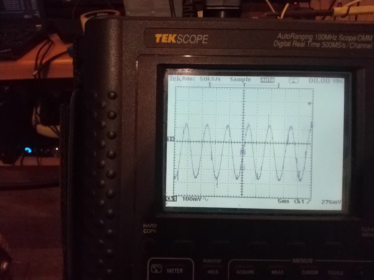
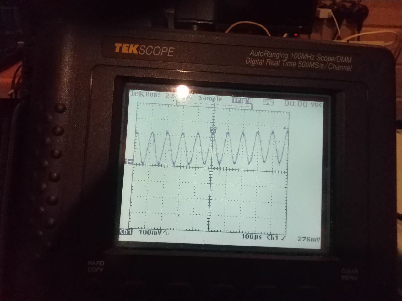
A short table with results:
It seems that active battery without the capacitor increases amplitude of signal at the base of Q26 with frequency, especially the original battery.
Has it been done intentionally? I just can't see a reason. This imperfection of AB probably decreases stability at HF and slightly lowers bass.
Measurements have been made with Tektronix THS720 and P5102 voltage probe.
I can't wait to measure these batteries in the amp itself
")
-
2
-
-
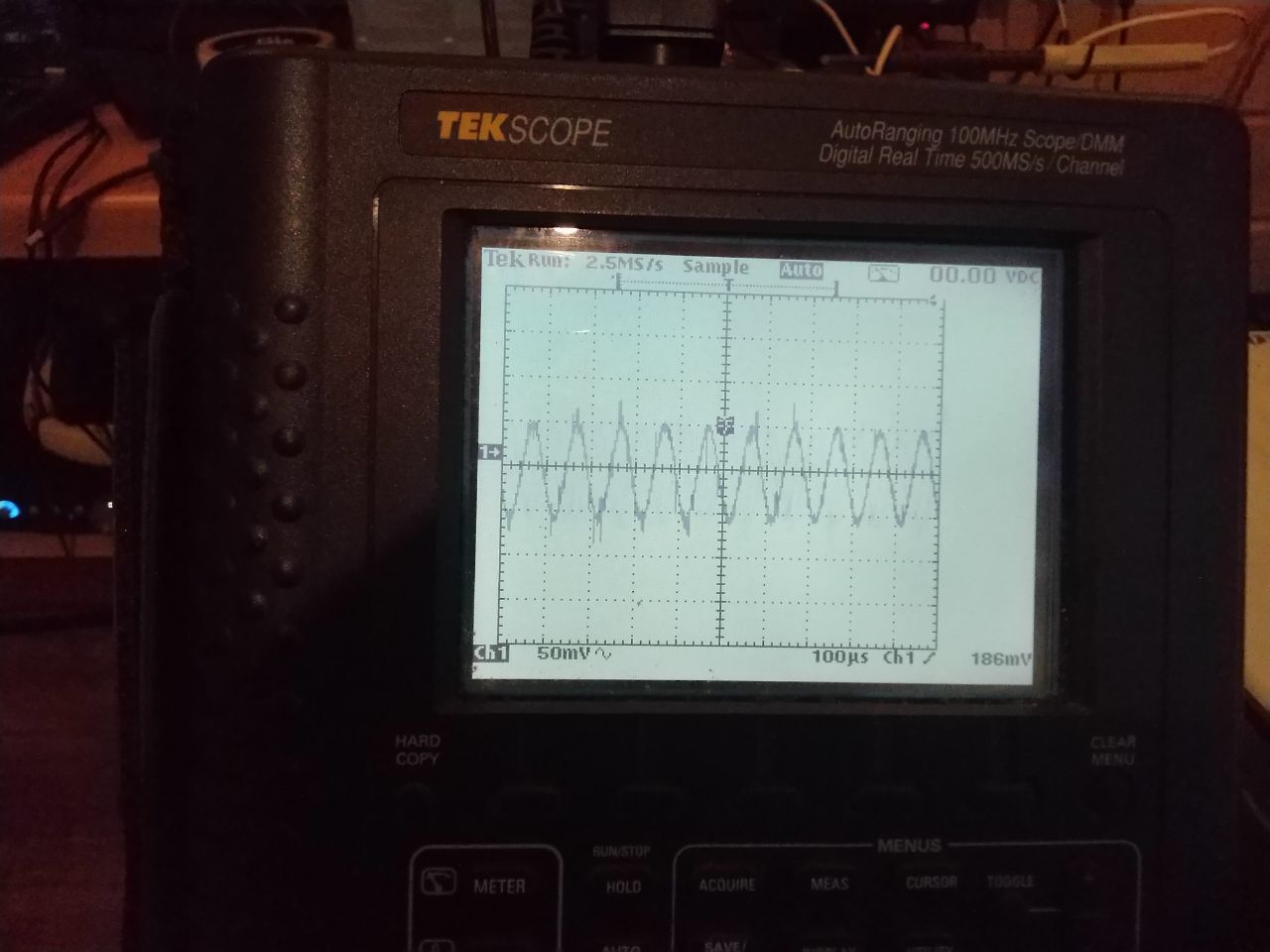
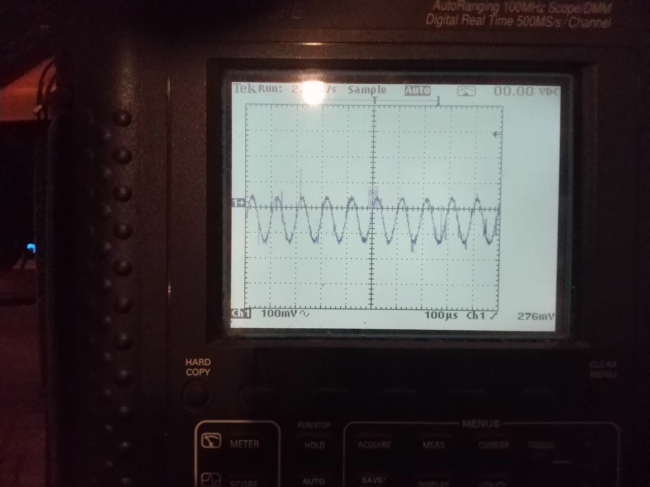
The new battery with added capacitor:
1. 120 Hz, power off
http://ixbt.photo/photo/406668/17916TMfujOMyVu/Hgj7GE8yHX/1514671.jpg
Amplitude is about 200 mV
2. 120 Hz, power on
http://ixbt.photo/photo/406668/17916TMfujOMyVu/Hgj7GE8yHX/1514672.jpg
Amplitude is about 20 mV (!)
__________________________________________________________________________________________
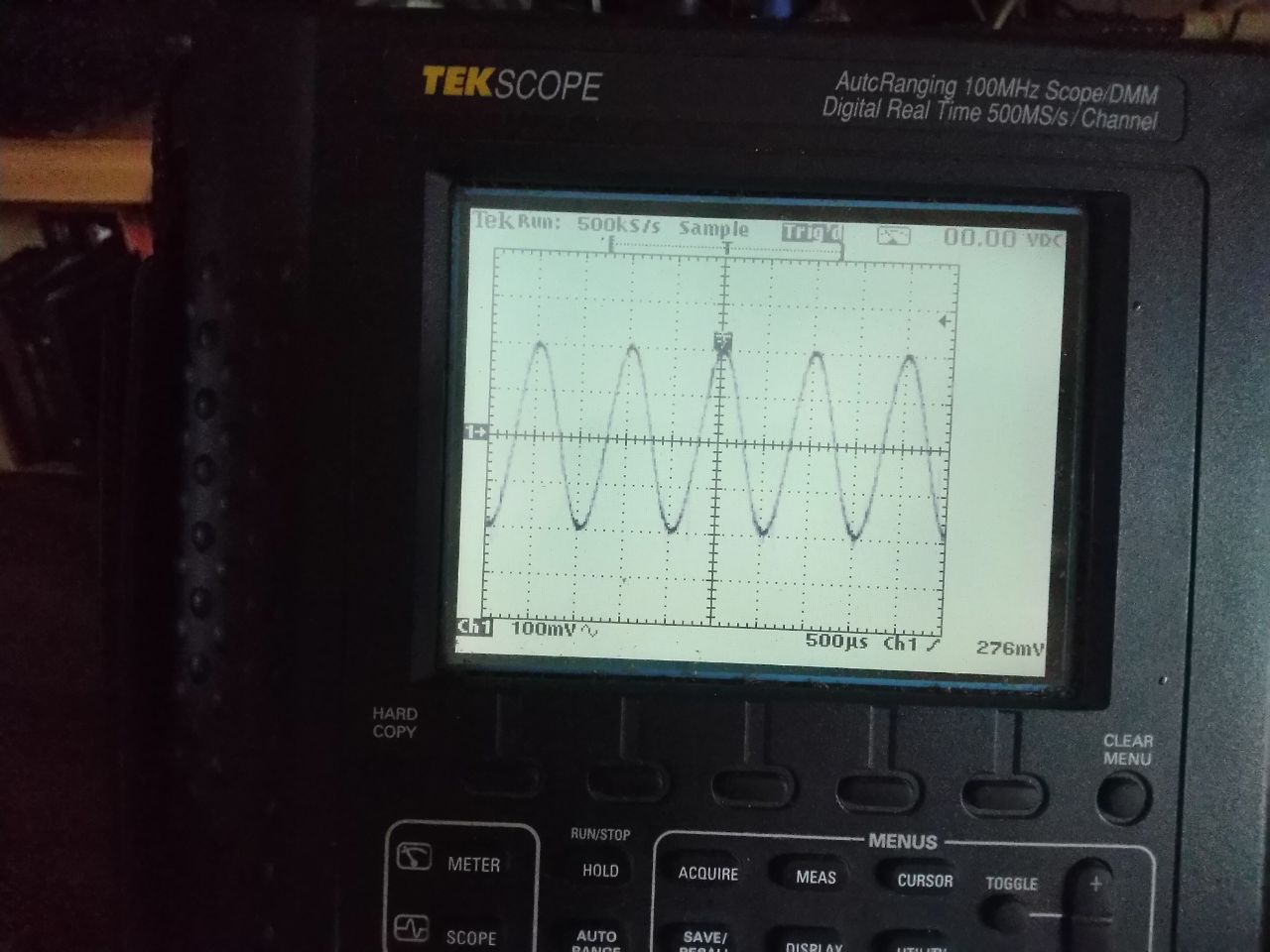
3. 1000 Hz, power off
http://ixbt.photo/photo/406668/17916TMfujOMyVu/Hgj7GE8yHX/1514667.jpg
Amplitude is about 200 mV
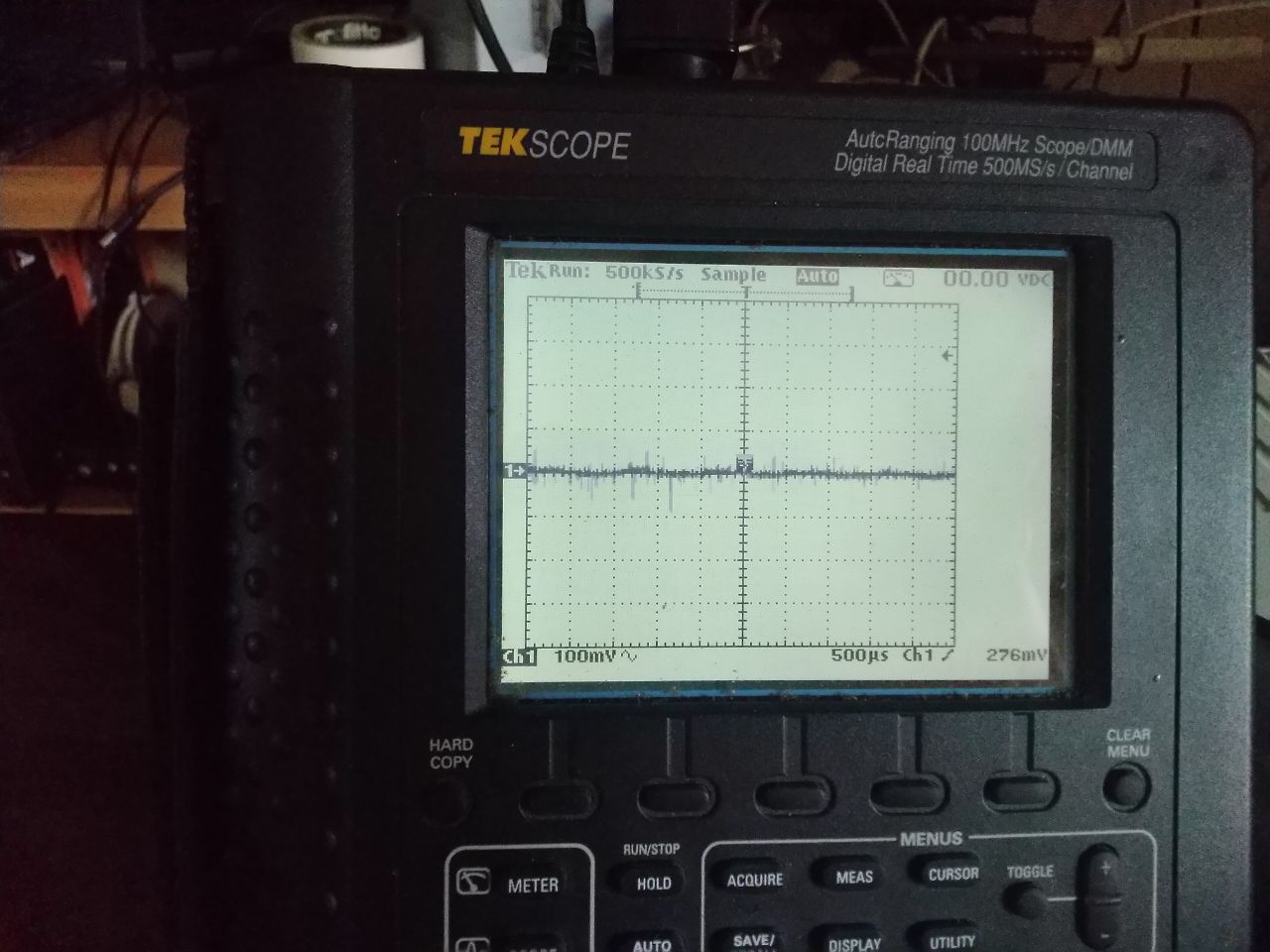
4. 1000 Hz, power on
http://ixbt.photo/photo/406668/17916TMfujOMyVu/Hgj7GE8yHX/1514668.jpg
Amplitude is about 10 mV or less (!!)
__________________________________________________________________________________________
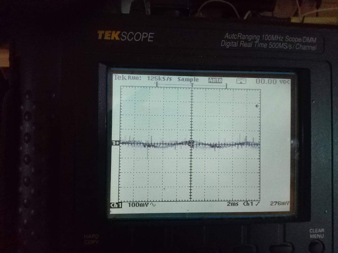
5. 10 kHz, power off
http://ixbt.photo/photo/406668/17916TMfujOMyVu/Hgj7GE8yHX/1514673.jpg
Amplitude is about 100 mV
6. 10kHz, power on
http://ixbt.photo/photo/406668/17916TMfujOMyVu/Hgj7GE8yHX/1514674.jpg
Amplitude is about zero (!!)
__________________________________________________________________________________________
Adding the bypass capacitor makes the active battery much closer to an ideal "voltage drop" element. I think that increasing the capacitance to 4000 or 5000 pf will decrease the measured voltage even in the case of low frequencies like 100hz.
-
2
-
-
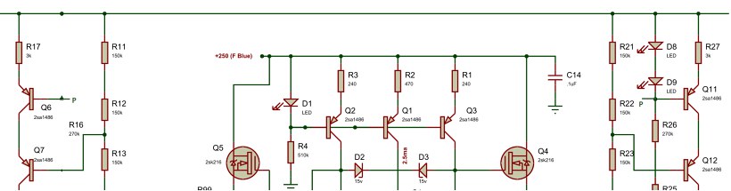
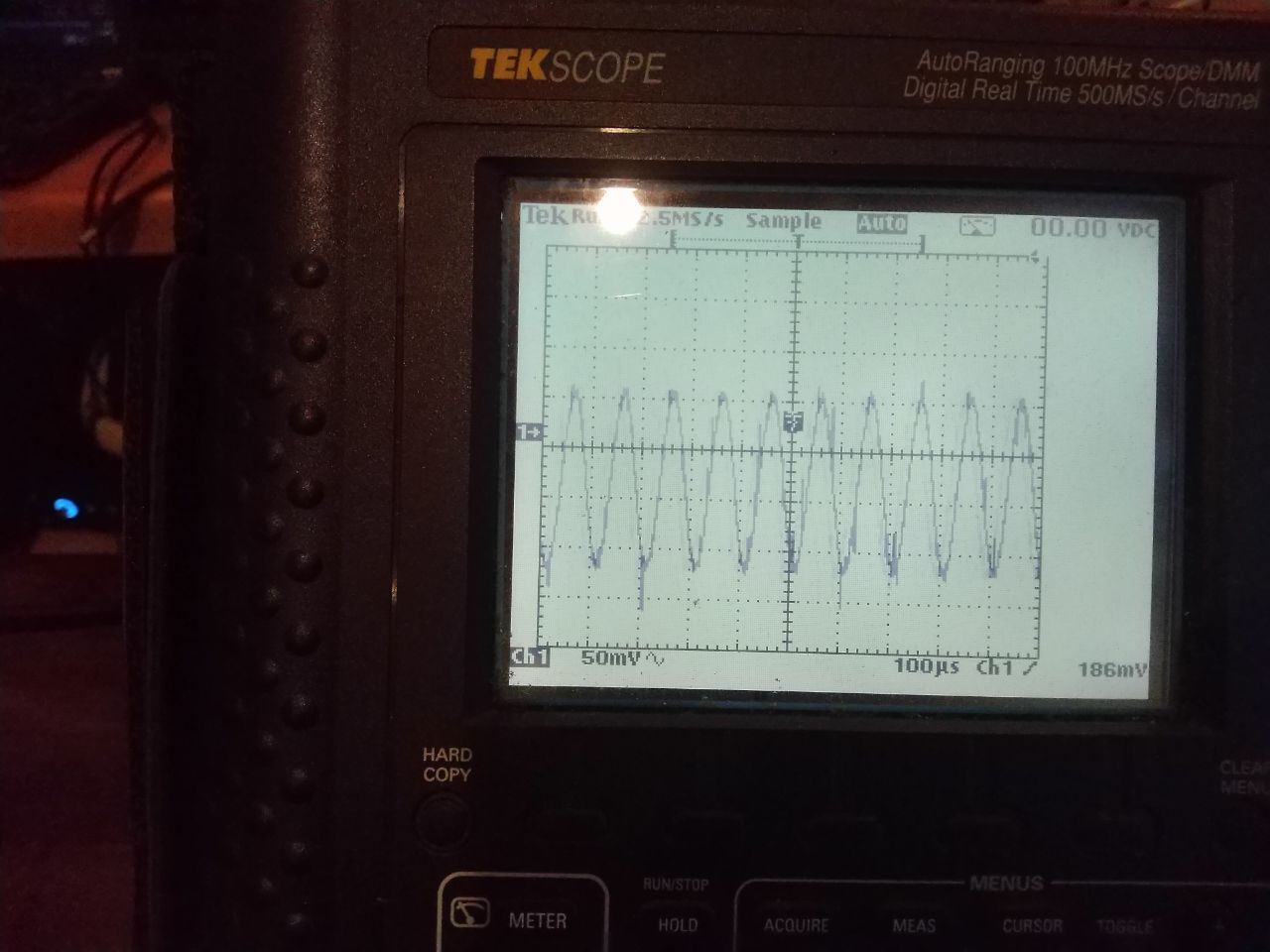
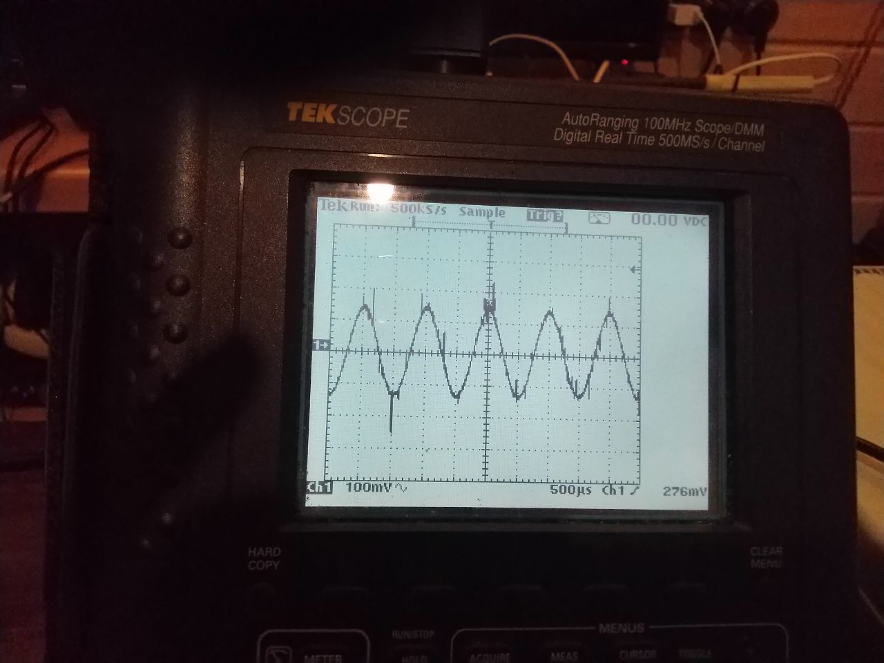
The second version of AB was taken from this post.
We changed R43-R44: 140k -> 150k, MPSA06 -> HN4C51J and FJPF2145 -> 2SC3675 selected with the best hfe.
Why ?
1. We decided to slightly lower supply of LT1021 - it is still enough for normal work of this voltage source.
2. HN4C51J has better hfe and also I prefer to use double transistor in one case in current mirrors.
3. 2SC3675 has lower input capacitance and better hfe.
STN9360 has much higher current gain and lower capacitance in comparison with 2SA1486/2SA1413 and we thought that performance of this battery should be much better. And so it turned out:
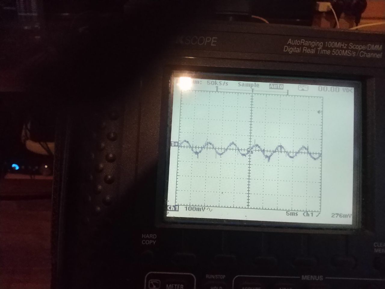
1. 120 Hz, power off
https://ixbt.photo/photo/406668/17916TMfujOMyVu/Hgj7GE8yHX/1514659.jpg
Amplitude is about 200 mV
2. 120 Hz, power on
https://ixbt.photo/photo/406668/17916TMfujOMyVu/Hgj7GE8yHX/1514660.jpg
Amplitude is about 45 mV
__________________________________________________________________________________________
3. 1000 Hz, power off
https://ixbt.photo/photo/406668/17916TMfujOMyVu/Hgj7GE8yHX/1514661.jpg
Amplitude is about 200mV
4. 1000 Hz, power on
https://ixbt.photo/photo/406668/17916TMfujOMyVu/Hgj7GE8yHX/1514662.jpg
Amplitude is about 80 mV
__________________________________________________________________________________________
5. 10kHz, power off
https://ixbt.photo/photo/406668/17916TMfujOMyVu/Hgj7GE8yHX/1514663.jpg
Amplitude is about 75 mV
6. 10kHz, power on
https://ixbt.photo/photo/406668/17916TMfujOMyVu/Hgj7GE8yHX/1514664.jpg
Amplitude is about 50 mV
__________________________________________________________________________________________
The new battery performs much better!
But it is still is far from ideal. Why ?
At the next day Dmitry noted that capacitance of STN9360/2SA1486(Q17p/Q17) and really high resistance of the voltage divider (R33-R34) make a low-pass filter. Could it be the cause of problem ?
He added one 2200 pf teflon capacitor between the low end on R34p and the base of Q17p transistor.
Results of the measurements are in the post below
-
2
-
-
Still waiting for last parts.... 🥱
And waiting for them to be delivered, I and my friend Dmitry decided to tests a performance of the active battery at hight frequencies.
The scheme of the stand has been given by @Kerry. Thanks!
We just slightly modified it.
Safety note: we supplied the battery by a source completely decoupled from the mains.
That is why our generator is alive. Be careful.
All the batteries are set to 740V.
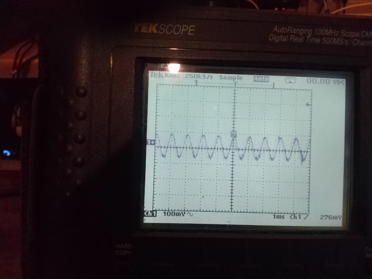
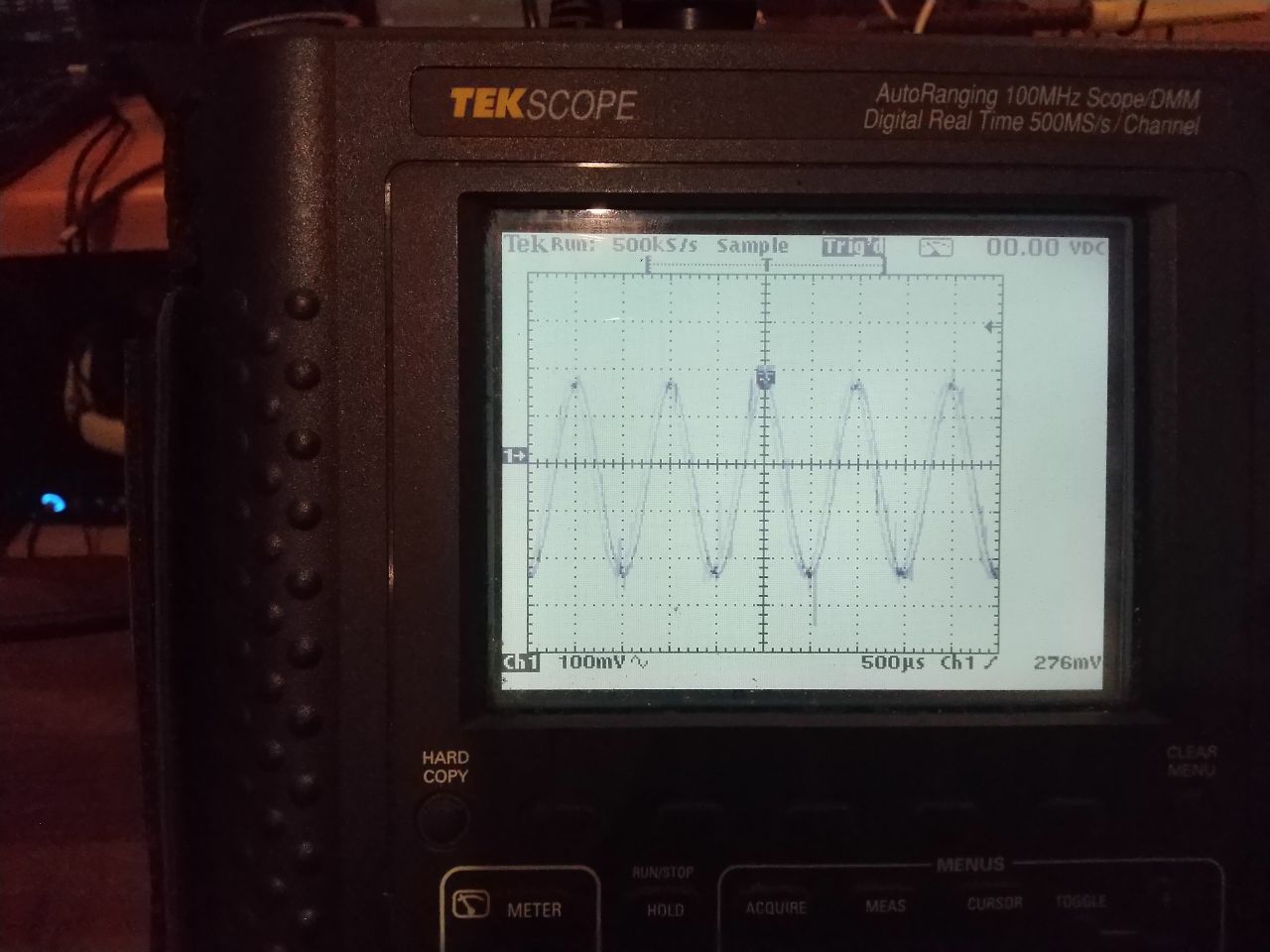
The first battery is the original one with 2SA1486 -> 2SA1413 and 2SK246 -> 2SK208 and 2SC3381 -> HN4C51J. The first two pairs are the same transistors in different cases.
Results of the measurements:
1. 130 Hz. Power off.
https://ixbt.photo/photo/406668/17916TMfujOMyVu/Hgj7GE8yHX/1514651.jpg
Amplitude is about 200 mV
2. 130 Hz. Power on.
https://ixbt.photo/photo/406668/17916TMfujOMyVu/Hgj7GE8yHX/1514652.jpg
Amplitude is about 100 mV
3. 1000 hz. Power off.
https://ixbt.photo/photo/406668/17916TMfujOMyVu/Hgj7GE8yHX/1514653.jpg
Amplitude is about 200 mV
4. 1000 hz. Power on.
https://ixbt.photo/photo/406668/17916TMfujOMyVu/Hgj7GE8yHX/1514654.jpg
Amplitude is about 140 mV
5. 10 kHz. Power off.
https://ixbt.photo/photo/406668/17916TMfujOMyVu/Hgj7GE8yHX/1514655.jpg
Amplitude is about 90 mV
6. 10 kHz. Power on.
https://ixbt.photo/photo/406668/17916TMfujOMyVu/Hgj7GE8yHX/1514656.jpg
Amplitude is about 100 mV 😨
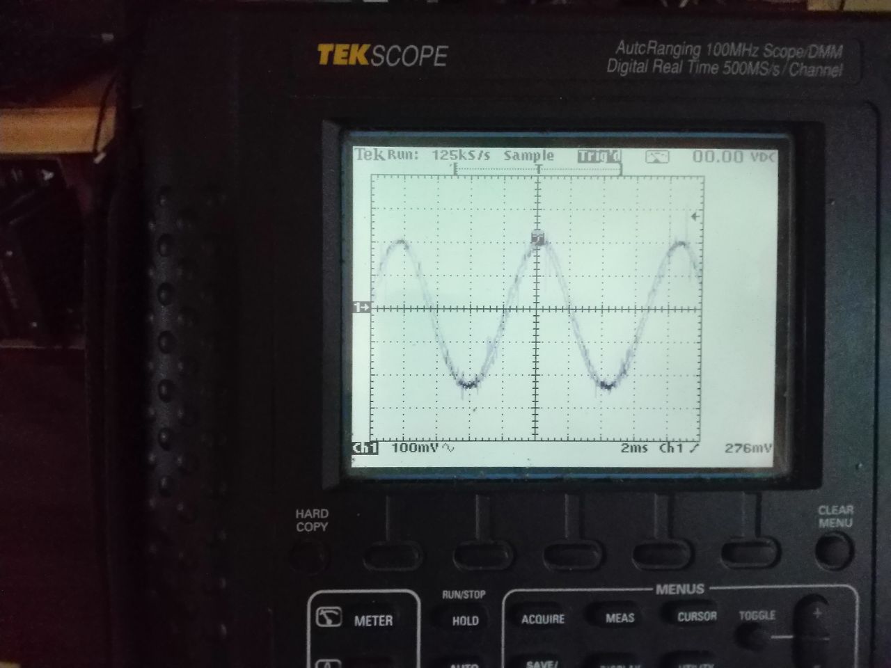
The questions: Shouldn't there always be zero volts AC ? Shouldn't the battery always stay at 740V after powering on?
It looks like the active battery in the T2 scheme suppresses low-frequency signal.
It is a problem ?
We decided to test another version of the active battery.
-
2
-
-
29 minutes ago, simmconn said:
Ah, okay. Sorry I misunderstood the question. It’s certainly possible, but usually the two CCS blobs are physically away from each other. IMHO given the other potential component mismatches, sharing the same LED string may not make a big difference in the current matching between the CCS.
I am trying to make all the components to be in pairs 🙂
I don't think that the difference will be big, especially due to matched LEDs. But.... why not ? I see a very minor advantages with no disadvantages.
Oh... and I don't think about current matching, but only about the noise of the LEDs.
-
-
21 minutes ago, simmconn said:
My take is that 2 LEDs in the string allows a higher emitter resistor value and therefore better local NFB. Sim shows that the effective impedance of the CCS roughly doubles with 2 LEDs vs 1. That come at a cost of reduced voltage compliance range and slightly increased power consumption. They are not a big deal for high voltage CCS, though.
No no, I don't want to use one LED instead of two.
I want to use the same pair of LEDs to feed both CCSs, connecting, for example, D8 and D9 to both Q11 and to Q6.
-
@kevin gilmore, what is the point in using two pairs of LEDs: D4-D5 and D8-D9 ?
Woudn't it be better to use one pair for both halves like it is done in the input stage ?
It gives us mutual substraction of a LED's noise for example.
-
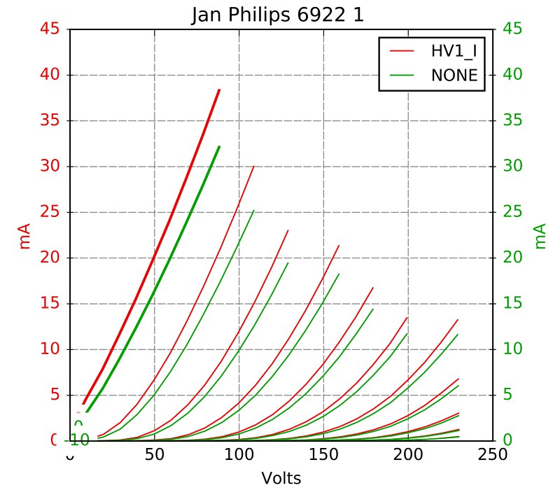
About tubedepot's service:
1. They sent me 2 6922 "Jan Philips" tubes instead of 4
2. I checked "balanced triodes" box. What I get:
The second tube has quite similar triodes unlike this one....
-
@sbelyo , do you think about possible substitution?
I've found interesting transistor: TTC5460B. It is available at chip1stop.
It has much lower max current but also lower Cob. I think you could check if it is suitable for you.
-
I heard that goldpoint's attenuators are good enough.
-
19 hours ago, audiostar said:
More pics, please 🙂 Looks awesome!
I promise to make more photos when my AB test stand will look better. And thanks for your words!
It will be soon.
19 hours ago, audiostar said:Did you use the 2SK208-Y(TE85L,F) or the 2SK208-R(TE85L,F)
I use 2SK208-GR. It is the same as 2SK246-GR, of cource except the thermal parameters.
19 hours ago, audiostar said:Btw, any special reason you did use SMD resistors for R12, R13?
No, the only reason is that I already had them)
There is no high voltage around them or high current through them.
-
2
-
-
I've made a simple stand, thanks to Kerry, and all ABs have passed all tests, dropping now silently 740 volts as it shoud be 🙂
-
1
-
-
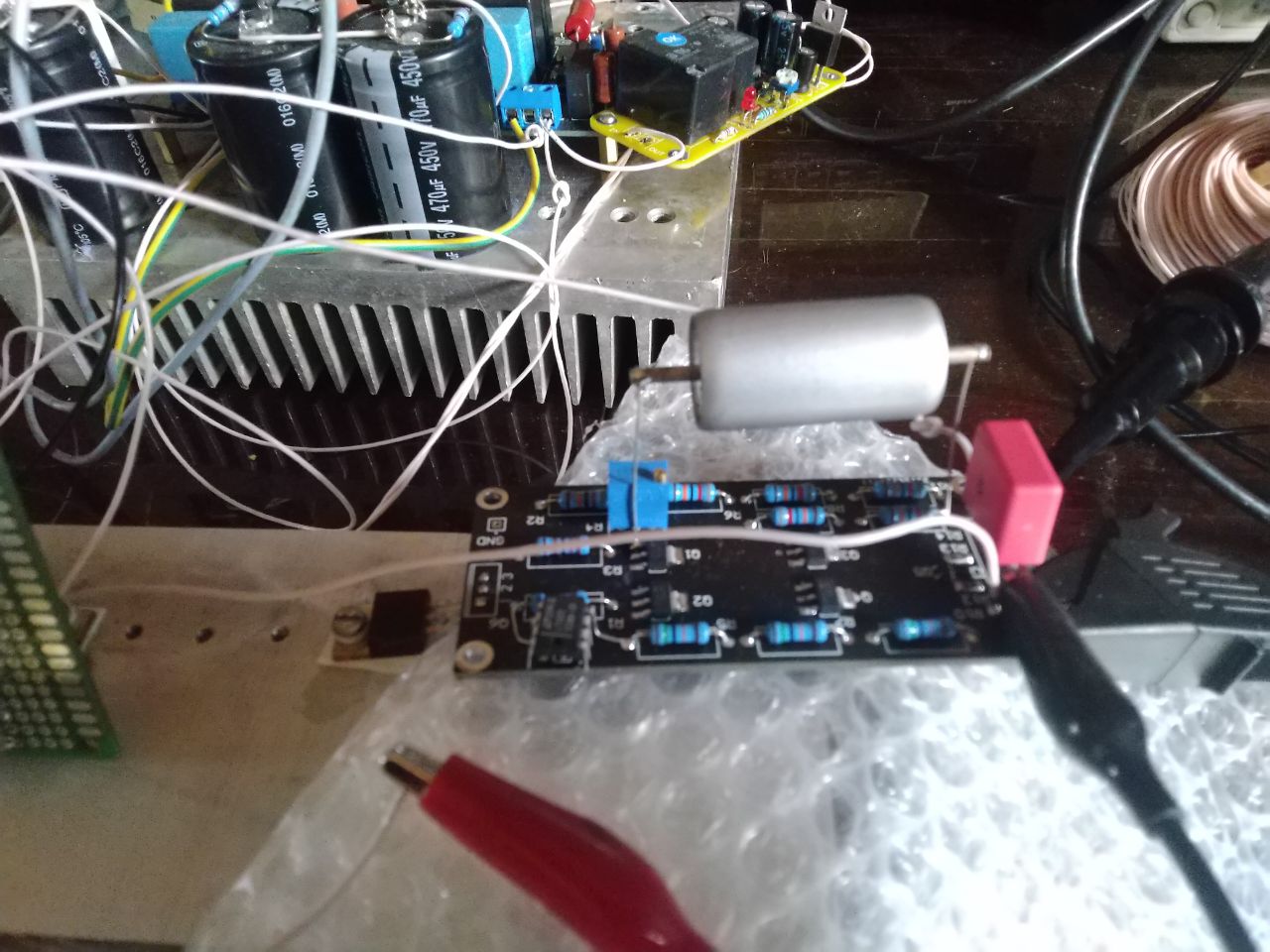
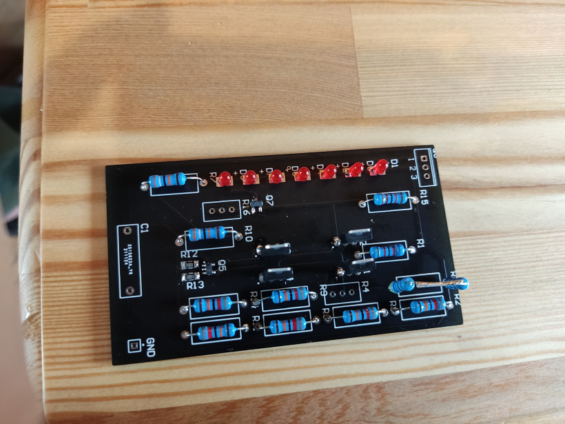
Preparing an old style active battery with LEDs. I've decided to make separate boards to test them separately from the main amplifier.
Small changes in the AB:
1. replaced 2SC3381 with HN4C51J - I've measured them and they are very good dual bjts with very close halves.
2. replaced 2SA1486 with 2SA1413. The same transistor with different case. Power dissipation here is close to zero, so I decided to leave 1486 for hotter places 🙂
3. 2SK246 -> 2SK208. The similar situation here with the same transistor in a different package.
4. LEDs are LTL-4221NLC
-
5
-
-
One my friend needs 20 pcs, so I am in for 35 pcs.
-
I am in for 15 pcs
-
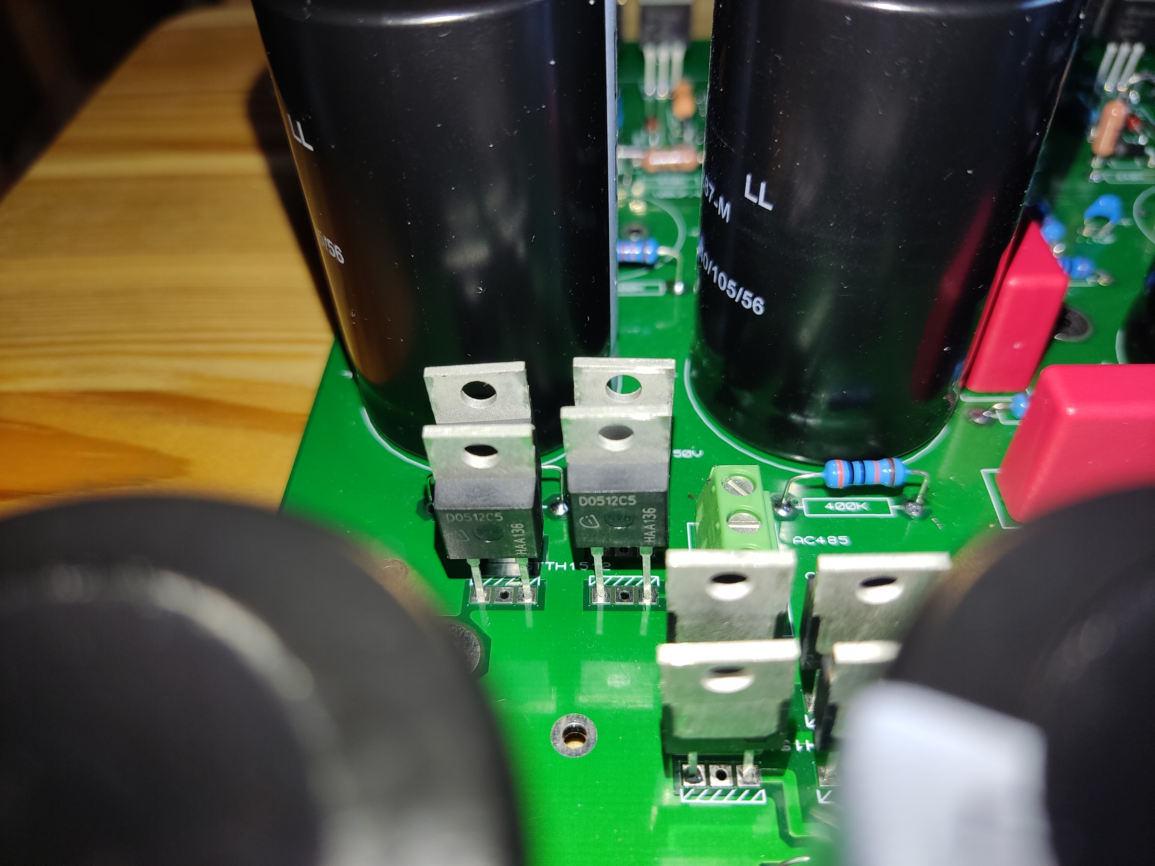
I also think that the short-term changes in voltages(with fast changes in current consumption) could be caused by the high(500k) resistance between 2SC3675(Q5) and FQP8N80C(Q4), which has a large Ciss (up to 2050 pf). It gives us a time constant up to 1.05 ms, which is not perfect. At least the next PSU, which I am going to make, will be done according to Jamesking's scheme. I like it more, and it would be interesting to compare.
-
The peculliarities of this assembly:
1. I've changed diodes to shottky ones with a low leakage current: IDH05G120C5XKSA1. Works well.
2. I've used more presicion resistors for voltage dividers. That is why I've used 2 resistors instead of one sometimes - I prefer to use 2 presicion resistors intead of 1 usual xicon if there is no required value in a shop. This is also a cause of 502 voltages in +- 500 line: i've used a pair 271k + 221k instead of 490k resistor. And 120k + 120k for 240k and 145+145 for 290k. All the mentioned resistors are +-0.1% and less then 25 ppm.
3. most HV parts are slightly raised above the board.
4. I've decided not to solder the Low Bias part.
5. I use UF4007 instead of 1N4007
6. 0.1 uF capacitors are X7R. I don't like ceramic capacitors, but there are no alternatives with a suitable size (. At least I use 100V instead of 50V. It lowers capacitance changes with applied voltage.
-
5
-
-
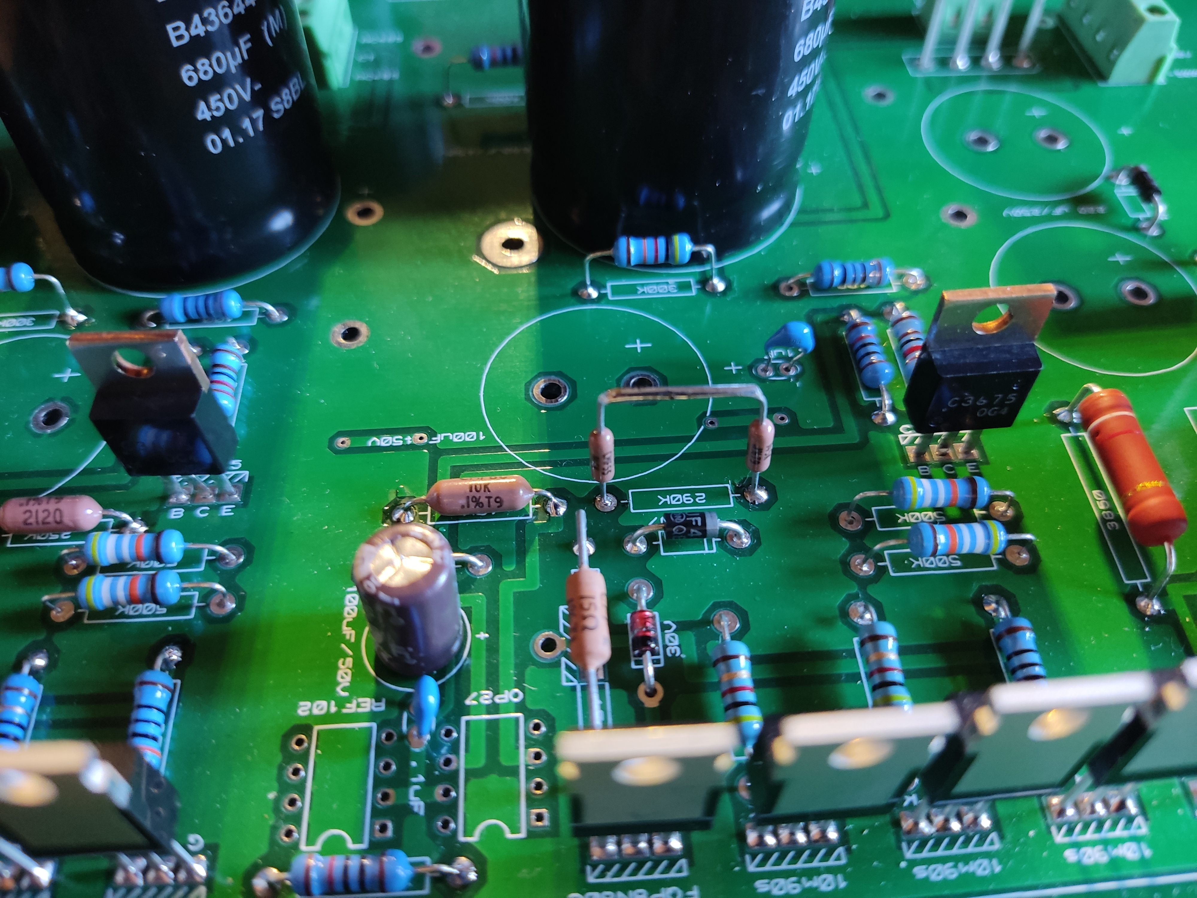
I've soldered 400k resistors in final....
The first T2 PSU works now. I've tested all the channels.
http://ixbt.photo/photo/406668/17916TMfujOMyVu/Hgj7GE8yHX/1502281.jpg
Voltages:
+250 -> +250
+500 ->+502
-500 -> -502
- 560 -> -563
- 260 -> - 263
I've also checked its transiend characteristic by loading it with an active load with a meander current from 5 to 40 mA and back. So there were changes in voltages up to 15-20 mV for +-500v and up to 10 mV for +250 and -260v.
-
2
-


The ultimate DIY? A Stax SRM-T2!
in Do It Yourself
Posted
Have you checked the output voltages without a load?