jbozek
Returning Member
-
Joined
-
Last visited
Everything posted by jbozek
-
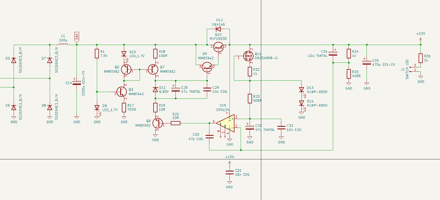
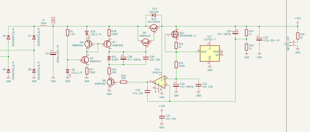
hi! i settled down with standard dn2540 current source (bit higher current) and two HLMP-6000 low noise red leds which gives a 3,1V reference voltage. led thermal drift is not a problem in my case. how does led noise compare to voltage re ference ic-s (LT1021 for example)? as always any answer or critic is appreciated! btw this is the best sounding thing i have tried with my power supply so far

-
your answers are much appreciated! ok, so i need to play with current source and voltage reference. for now i replaced DN2540 with BSS159N which behaves better with lower voltage. sound difference is already much much better.
-
Hi! I made an smd GRLV power supply for my dac a have some strange results. I would appreciate any help. Output voltage is 10.5V (it can't be any other voltage unfortunately), input voltage is 12VAC (a bit higher) so on the input of the GRLV is about 16VDC. Output current is very constant - about 500mA I lowered the 150R driver resistor to 100R - this resulted in more controlled sound. I tried to remove MMBTA42 from the pass transistor so that I have single transistor instead of darlington. I removed opamp input protection diodes - is this a good idea at 10.5V output voltage? - With default configuration (darlington) I get very tight and powerful bass, mid range is very rich, but highs are mediocre. - With MMBTA42 removed (single pass transistor) highs got very right and effortless, but the bass is thin and everything is less dynamic. BTW I am using DYNALO single ended headphone amp with GRLV power supply and Sennheiser HD560S.7 Did anyone had situation like that? Does anybody know how to explain this electrically?
-
thank you very much!
-
hi! i have a balanced diy dac with output capacitors to block dc component. can i connect the dac to ss dynalo without capacitors? dac has a dc bias of 2.7V per output. i know for single ended this is not an option, but im not sure for balanced...
-
thank you! i will integrate raspberry in my dac project
-
thank you very much. i will post everything here, but it will take some time because i am a student with very limited buget
-
hi! i would like to share my work with you. i am working on a small susy dynalo but with grlv psu and much better cooling capacity. also i will change the pzta tranzistors with toshiba 2sc2881 and 2sa1201 because they do not heat as much as pzta for some reason, and they are smaller (sot 89). it is a work in progress. for now i only developed an amp (one channel) and psu section without anything else. in following pictures you can see one amp channel and psu with meanwell switchers feeding the grlv (maybe i will put a transformer). bottom side of the pcb has exposed copper (large white spots) which will make contact with case to have more thermal mass. as you can see, there are lots of vias and they connect top and bottom part of pcb around output transistors to increase thermal surface. size of one channel section is 42x87 mm, and psu section is 98x61 mm. so i plan to fit finished project in 150x150mm case. i am a student so it will take time to build this thing, and of course a lot of hard earned money . i hope you like it! pictures: https://drive.google.com/drive/folders/1x2SQcV86kyMJL18twtRnseKntS9kgVBa?usp=sharing
-
can i replace jfets with that340 in old dynalo SE circuit without any mods? some resistor are different
-
do you maybe sell LSK489 / LSJ689 ?
-
if i have a 50k pot, but need a 10k, can i put a 10k resistor parallel to amp input (or pot output)?
-
damn they are expensive
-
thank you very much, all of you!
-
can i maybe replace the jfets on original dynalo with that340? and what mods should i do? i think i must tune the ccs, and change pot from 50k to 10k. correct me if i am wrong
-
i would like to build it, but i am a student so cost is a big problem unfortunately
-
thank you for your response. maybe i will have the chance to build one someday
-
yes. it is an old jfet input dynalo. i was lucky to get matched jfet pairs, but they were expensive. i followed the old schematic with tht components, but made some modifications because i used smd components. and my version has slightly more power. power supply is not modded, equivalent smd components are available and i want to ask you something. is there much benefit to using balanced output? lets say i will use this amp only with sennheiser hd650 and it has enough power to drive it and it is completely silent.
-
biggest reason is cost. i am a student so cost is a problem. second reason, i wanted a somewhat small and compact all in one. maybe in the future i will make a balanced version
-
Hi! i would like to share my work with you. I made an dynalo amp powered by grlv power supply and a pcm1794a/cm6631a dac. Everything is totaly made by me. I also designed the pcb nd ordered it from JLCPCB. Amp offset voltage stays at max +-1mV and it is totally silent. Case is DOUK AUDIO. pictures: https://drive.google.com/drive/folders/1a6cbGFpN6s5EadR8DA_lb21ZFwOwzK4R?usp=sharing
-
Thank you very much!
-
Hi! i would like to share my work with you. I made an dynalo amp powered by grlv power supply and a pcm1794a/cm6631a dac. Everything is totaly made by me. I also designed the pcb nd ordered it from JLCPCB. Amp offset voltage stays at max +-1mV and it is totally silent. Case is DOUK AUDIO. pictures: https://drive.google.com/drive/folders/1a6cbGFpN6s5EadR8DA_lb21ZFwOwzK4R?usp=sharing