migo
-
Posts
22 -
Joined
-
Last visited
Recent Profile Visitors


migo's Achievements
Limited Edition Bronze Participant (4/6)
16
Reputation
-
and now for something completely different part 3
migo replied to kevin gilmore's topic in Do It Yourself
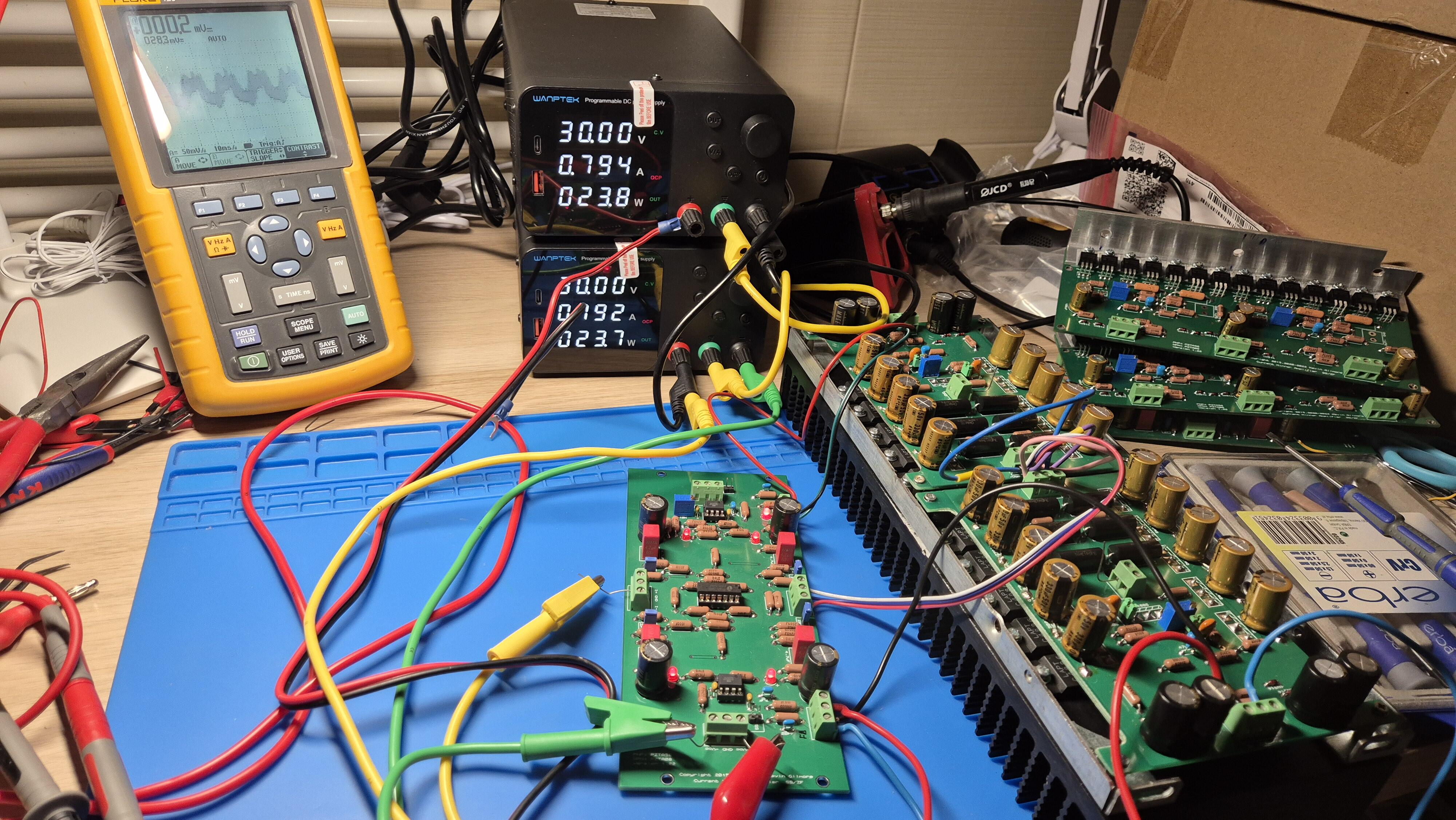
Hello, testing CFA3P here, seems to work fine, but it is running really hot at 150mA bias, wanted 250mA bias, but this impossible with used sinks. Powered with 30V PS. Do I need to change some values to run it with lower bias than designed 500mA? Thank you!
-
Thank you @Kerry! I'm curious, sorry, new mapping approach is based upon fixed table mapping or some smart math?
-
@Kerry Original code you published had 128 volume steps, but we have 8 relays here, with 0.5dB step. Was your intention to mask lower 128 steps to have not too much useless (quiet) steps to turn with the pot? With this is max. attenuation of -127.5dB (volume 0) and next step will be -63dB for volume 1. Thank you in advance for clarification.
-
and now for something completely different part 3
migo replied to kevin gilmore's topic in Do It Yourself
I have some NEW unused 2SA1860 and 2SC4886 to share here. Located in EU. If someone interested PM me please. -
and now for something completely different part 3
migo replied to kevin gilmore's topic in Do It Yourself
Anybody here with complete CFA3 split board version Mouser BOM for sharing? Thank you! -
and now for something completely different part 3
migo replied to kevin gilmore's topic in Do It Yourself
When do you disconnect one of CFA3 boards from power is that noise still there while using protector board? -
and now for something completely different part 3
migo replied to kevin gilmore's topic in Do It Yourself
Can you measure AHB2 too please? -
and now for something completely different part 3
migo replied to kevin gilmore's topic in Do It Yourself
Sorry for confusion the cable has source connected, it is standard cable. With source disconnected I mean that my CFA3 amp has this noise even with no source connected to it = with floating input. -
and now for something completely different part 3
migo replied to kevin gilmore's topic in Do It Yourself
I've adapted to this now: GND and power + and - goes from GRLV to each CFA3 PCB for each channel. Another wire goes from each GRLVs GND to central GND, wago used in my case here. No difference at all here unf. -
and now for something completely different part 3
migo replied to kevin gilmore's topic in Do It Yourself
Hi @MLAthank you for ideas. This is how I have it now. Two pot gangs are connected to one channel including separate GND to CFA PCB and another two to the other side. This is how it was done first when I've setup this amp for the first time and before I wanted to do it the "right way". I've reverted to this now, but it didn't helped 10R to chassis or not doesn't make difference. I was not aware that it can work this way too, will try... thank you! -
and now for something completely different part 3
migo replied to kevin gilmore's topic in Do It Yourself
Hi @audiostar, that cable is pin 1-1 only. But I think it is not that problem, because this noise is there when inputs are floating too with no device connected. I've no other 4 gang pot here, but I've tried with Kevins stepped digital attenuator and it was the same unf. Thank you, I've not tried this option so far I'll try it. -
and now for something completely different part 3
migo replied to kevin gilmore's topic in Do It Yourself
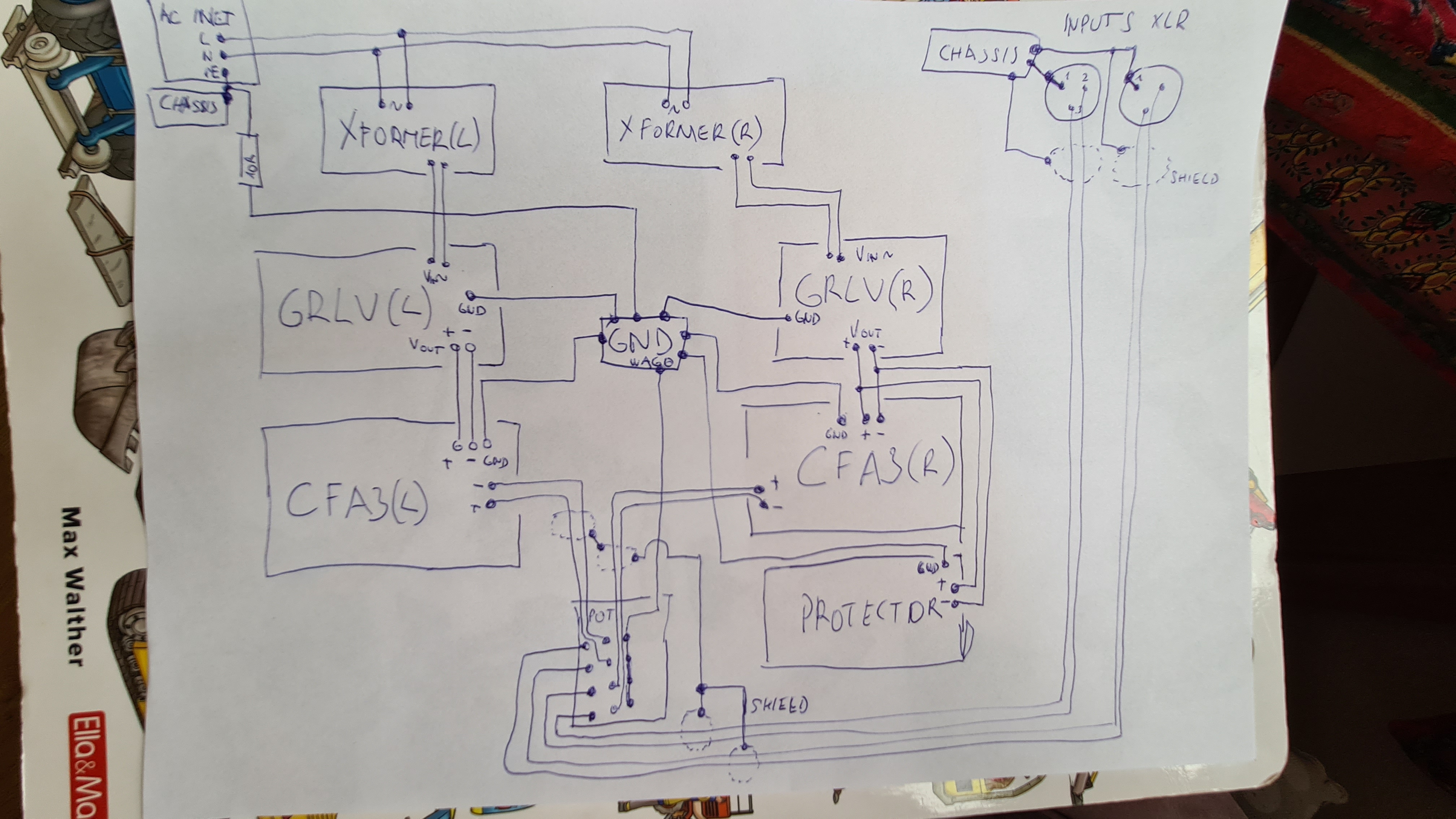
Thank you Pars, xformers are dual secondaries, block drawing is simplified. -
and now for something completely different part 3
migo replied to kevin gilmore's topic in Do It Yourself
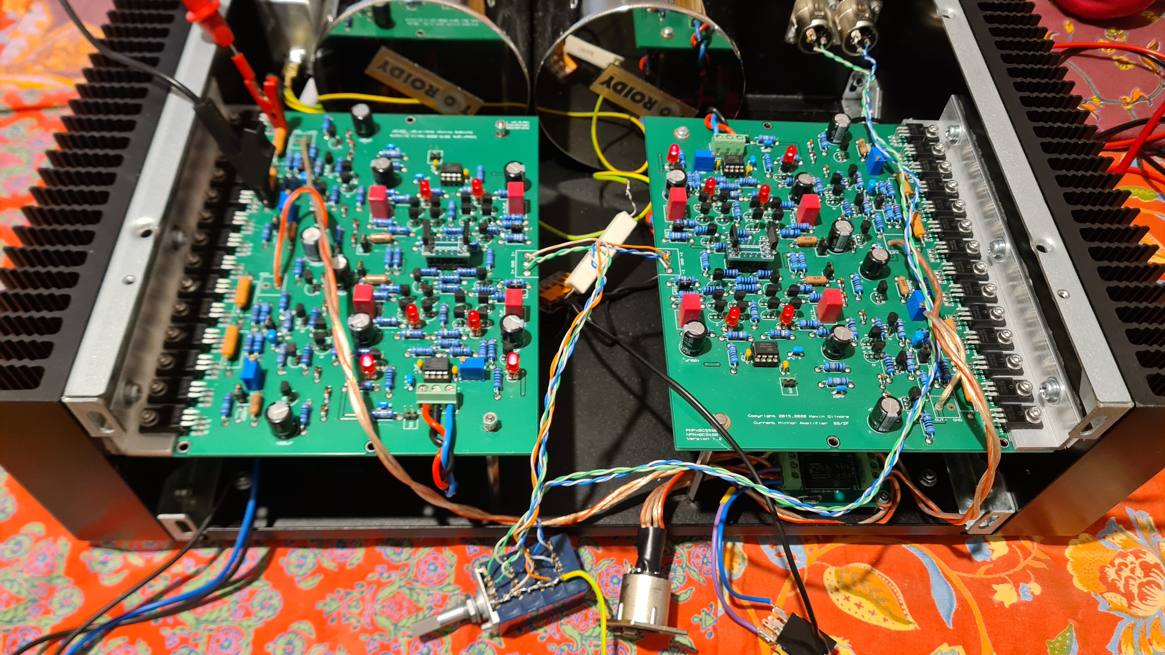
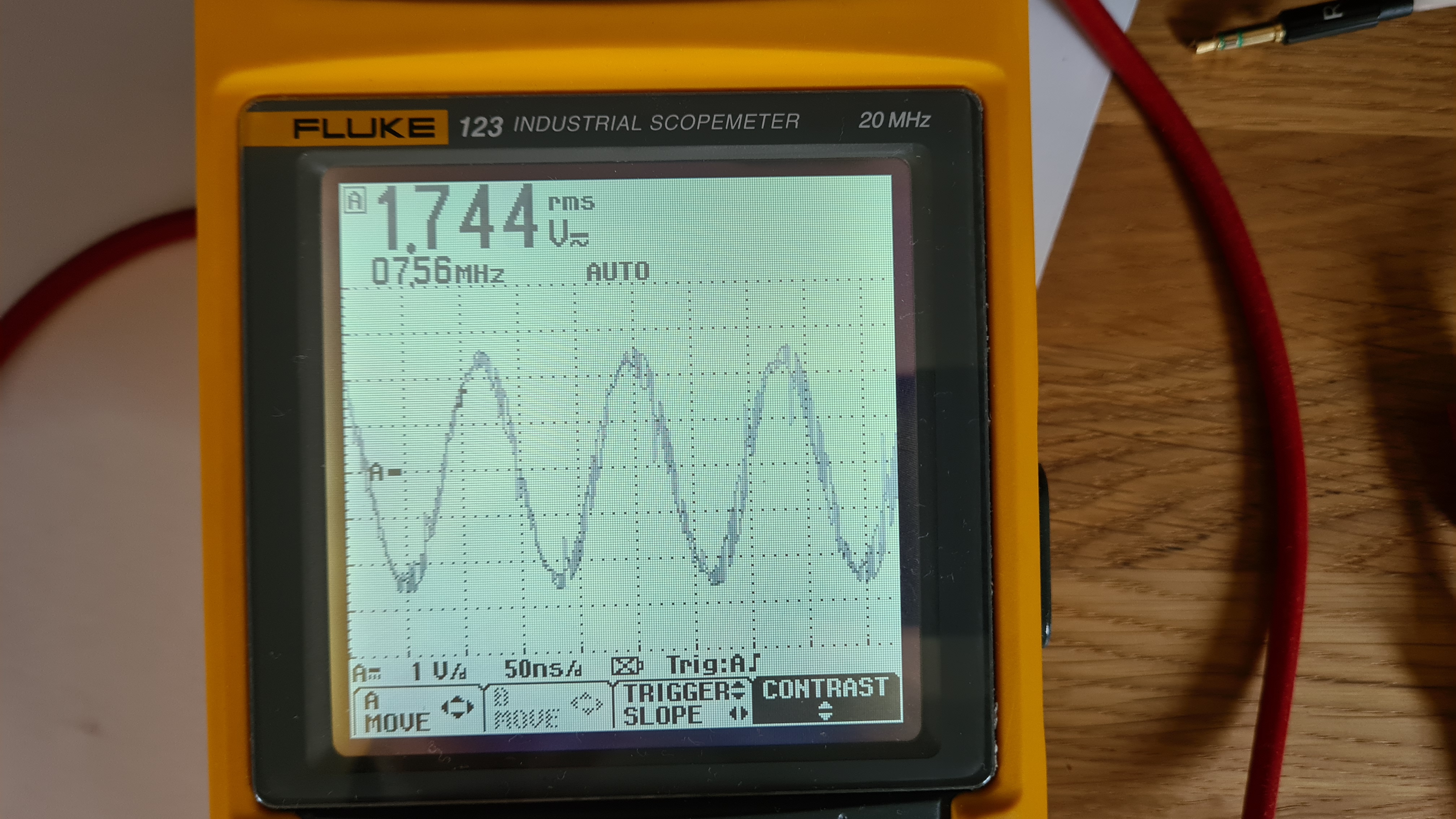
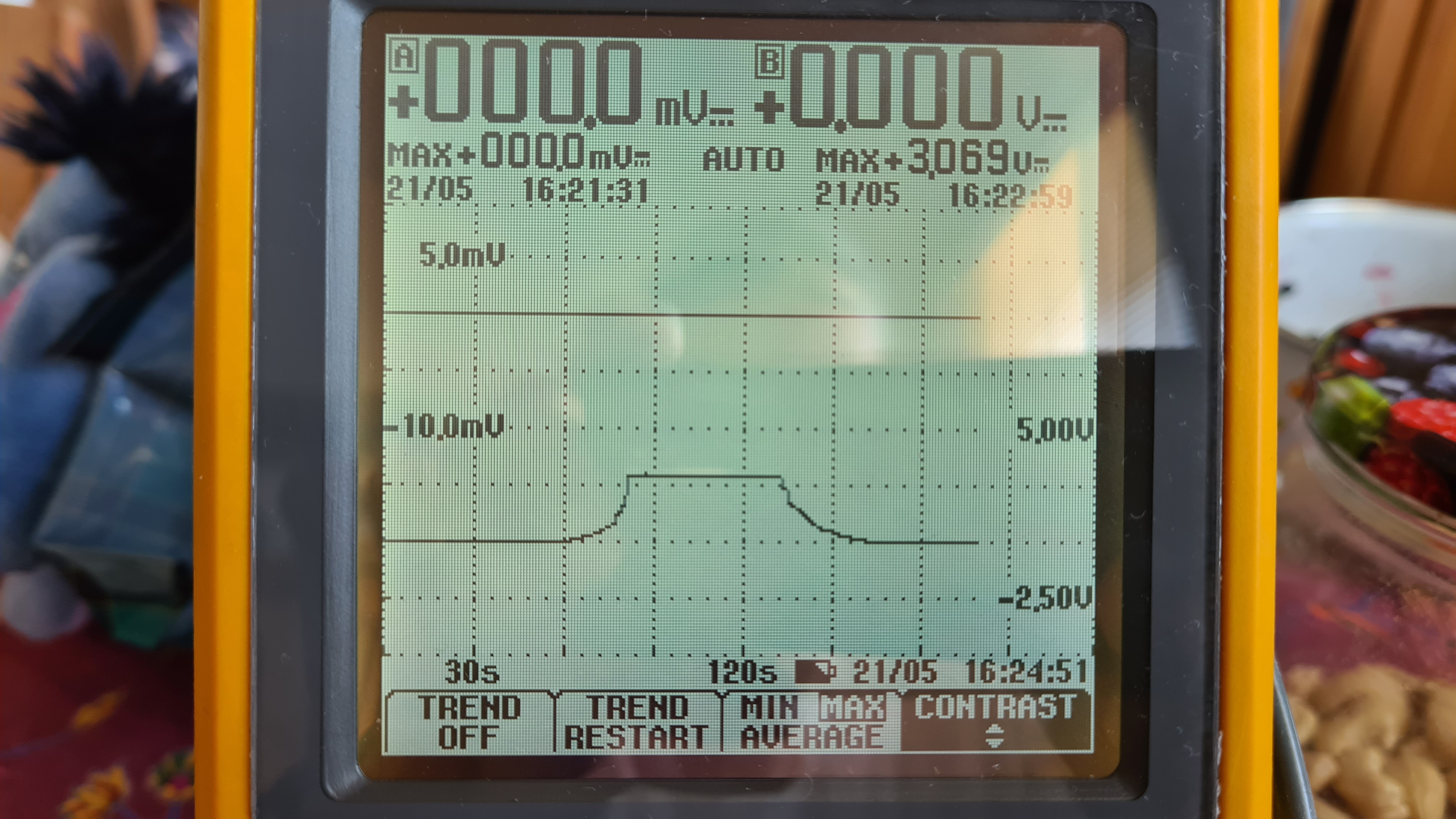
Hi, I want to ask for help or ideas what to try to do, I'm currently running out of ideas. I've build this CFA3 dual mono setup with 2xGRLV 30V power. It is actual state after two weeks of tinkering and reworking... It is somehow orthodox implementation of balanced noise self-canceling theory now. I've decided to rework grounding scheme two weeks ago. Here is block connection diagram: In short: I've one grounding point (signal reference) from which is GND connected to all amp PCBs. It is only GND connection for those PCBs, to not have ground loops. Everything looked nice after rebuild, I've connected my test HP (Koss sporta pro, Sensitivity 103 dB/mW) to SE output and listened to amp with floating input to evaluate noise. Everything was OK and I was able to hear very small amount of distant hum probably picked from large Xformers. I've measured bias and voltage on output 4pin XLR connector, all OK. I've connected 3m long balanced cable which came with Susvara and wanted to set 200mV output with 1kHz sine wave test signal from DAC. I've connected DMM to cable 3.5mm jack and wondered what happens! I've measured this: Wow! Disconnected that cable and measured again directly at amps XLR output connector and nothing there from this voltage! Connected XLR cable again and is there again. Ok, I was thinking it is not real that voltage and connected SportaPro HP again to SE output and no noise can be heard, so I let the Hp connected and connected that XLR cable to connector and immediately I can hear that ugly noise in SportaPro HP, so it is real unf. I've measured bias again and it raised from 200mV to over 300mV when XLR cable is connected to my amp, when I disconnect it, bias falls back to normal. This noise disappear when I set volume potentiometer to its maximum volume. It looks like there is some kind of ground loop but can't find where, all continuity/resistance measurements between all PCB GND and chassis GND seem to be OK, no loop nowhere. This noise disappear when only one CFA3 module is powered on. It doesn't matter which one it is, but you need to disconnect GND from that powered off module, not only + and - from GRLV. I've tried to swap GRLVs, than CFA3 modules, powered booth CFA3 from one GRLV, then from other one GRLV, left out protector board... still nothing... :(( It seems like those CFA3 modules are fighting each other. This leads me to one experiment, I've disconnected pot. signal GND (reference) from central star GND and connected it GND on CFA3 modules on signal input leads. The noise decreased/halved in intensity, but still not usable. Next experiment: I've separated GND for each CFA3 module = I've cut GND wire connecting all GND pins on pot. so that I've only connected together two GND pins for LEFT channel to LEFT CFA3 GND and two GND pins on pot for RIGHT channel to GND on RIGHT CFA3 PCB. Next improvement! Now is the noise there only at volume pot lowest volume, exactly when impedance between pot wiper and GND is 300 ohm and less. When I turn pot to higher volume there is no noise. I have stuck here. no more ideas. I'm sorry for this long post and bothering, but maybe some one here can see/know what is wrong, that I've overlooked. Thank you, Milan
-
Thank you Mr. Gilmore for help and all projects you have published for us to play with. I've wired 3.3V from arduino to one input and measured output voltage as suggested. It seem to work properly to me: Looks like Log pot to me like it should do. Kind regards, Milan
-
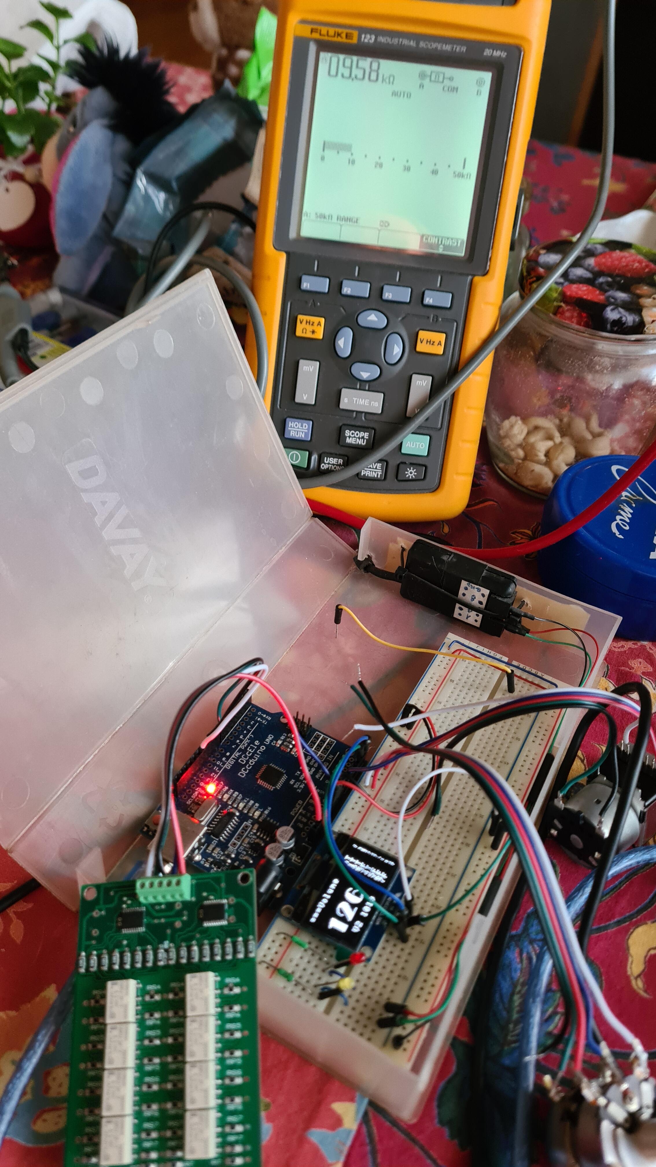
Hi @Kerry, I've sorted out problems with incorrect pot reading now. Relays are clicking at every position change but output resistance doesn't always change. I'm not sure if measured resistance is OK. At position 127 ohmmeter reads 10.2k, at position 126 ohmmeter reads 9.58k, at 0 position is reads 8.3R, at position 1 to 31 it reads 245.8R, at position 32 it reads 246.8, position 63 is 251R, then at position 64 it is 1.409k etc. Attenuator PCB used is V2.1. What is the best way of troubleshooting this? Thank you! Kind regards, Milan