jokerman777
Returning Member
-
Joined
-
Last visited
-
Don't know if I'm doing it right but I found in sim somehow this output stage doesn't like the high output impedance of the I/V converter gain stage. Adding another buffer in between helps. Partly the reason why you did a local feedback version of the preamp in the single ended version?
-
Curious what's the purpose of Q1/Q24 pair? The configuration seems to improve thd noticeably.
-
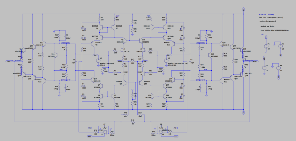
Too far down the road of downgrading? loading second stage down with resistors, loop gain went from 65dB to 25dB, thd will increase by more than an order of magnitude. No idea how much would be the sweet spot subjectively but can possibly be further tweaked. FET output, linearity not as good as triple BJT, just bc still try to cut corner on size... A quick search suggest lateral FET pretty much went extinct, for vertical ones should probably change vbe multiplier to something TO-126 and also put on heatsink?

-
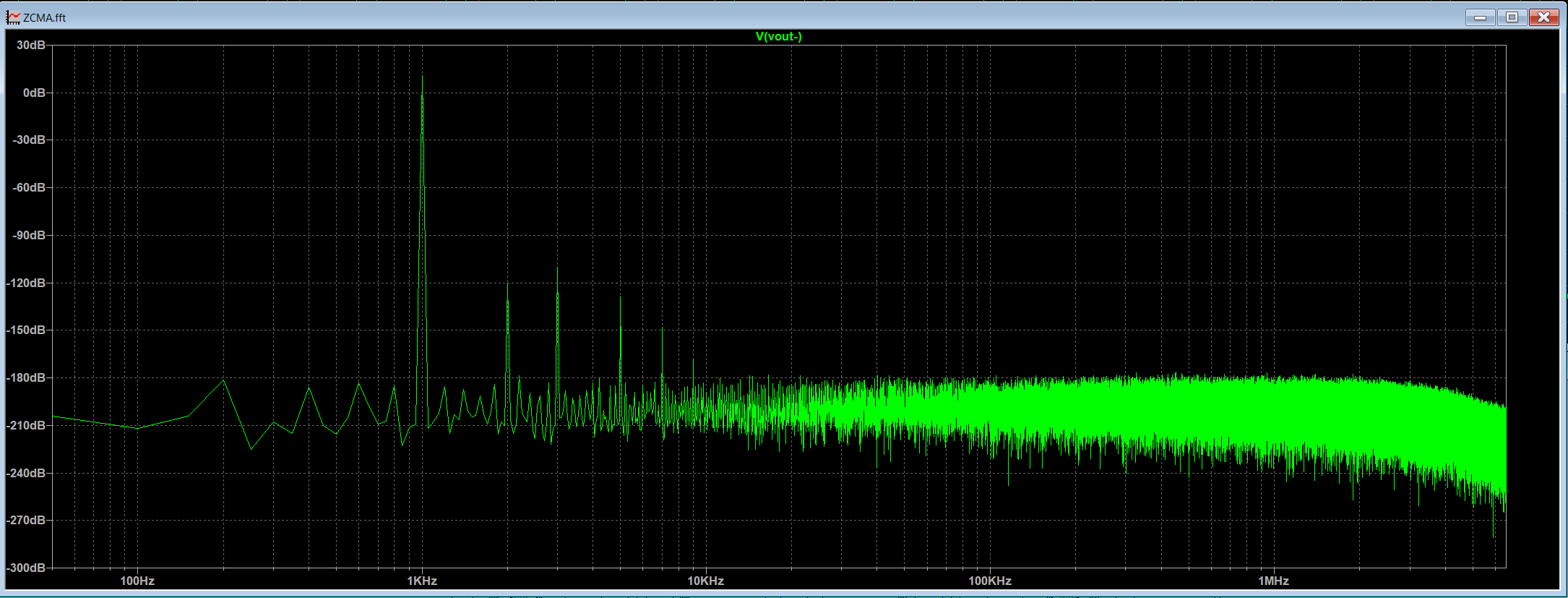
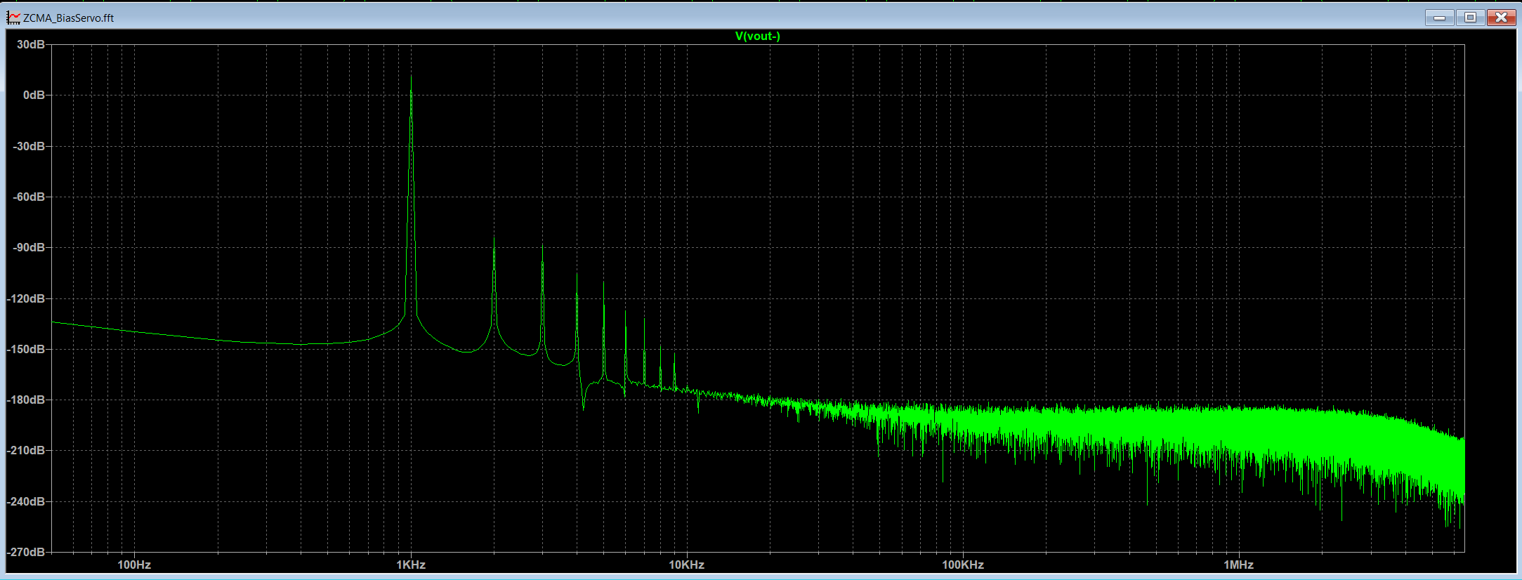
my bad could've just read to pages ago more carefully where the discussion on the matter already happened... I did a quick sim on Joamat's "new bias servo", 5Vpp on one side into 32ohm load, ofc not the same amp circuit, not opa445, and not assuming sim == real life behavior, but probably enough to convince me it's not gonna be free lunch. Below is before and after (also tried 300ohm load and difference is much smaller though). Now there is also KG's optocoupler version but between adding another 8 x opa445 and more and just doing thermal coupling right in the first place, well... 😃 And many thanks for the advice and detailed explanation! Yeah I'm aware of the generous amount of feedback used here, much like the original CFA2 right? where CFA3 is changed to open loop design with optional feedback config. I didn't "choose" to go with this way on purpose and haven't built/listened to enough stuff to form a particular preference on the camps between no feedback/some feedback/a lot of feedback (which kinda has a bad reputation). I'm pretty much just randomly exploring options now, for possibly a smaller scale project than CFA3 for my need. Might still jump back on doing the original if I got enough messing with spice


-
Thanks @JoaMat, this data is really helpful. From your measurement it does look like I really needed either bias servo or do it like the original for hopefully less drift. Nice soft start behavior too
-
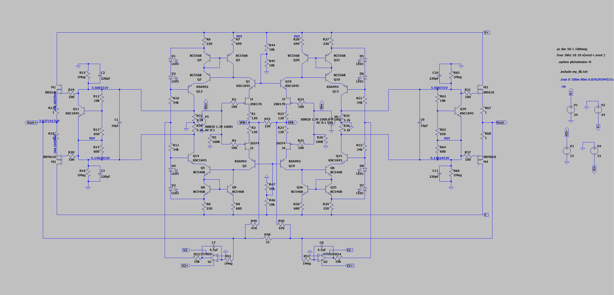
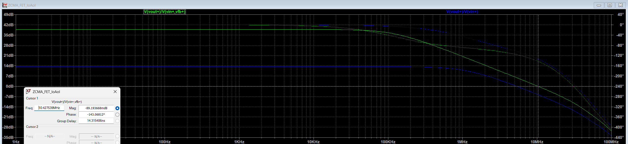
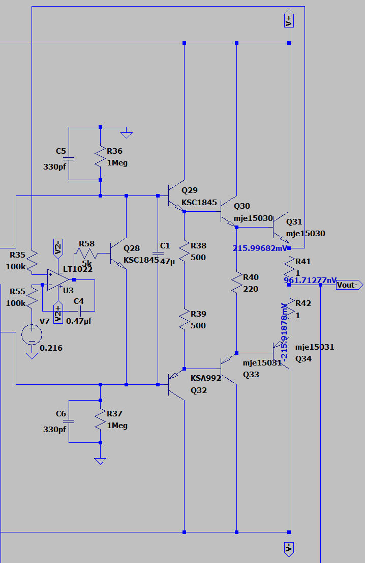
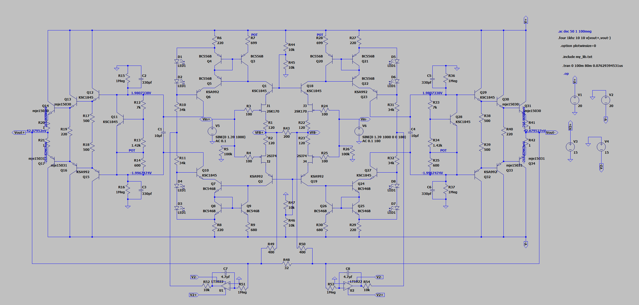
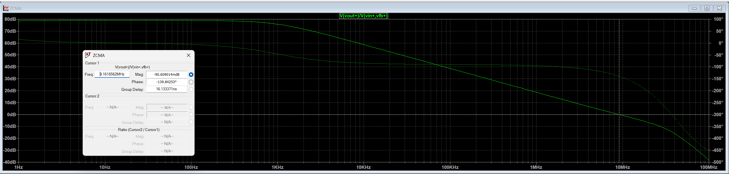
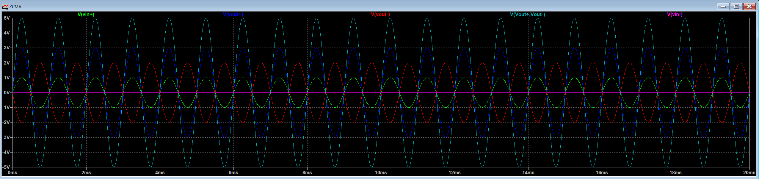
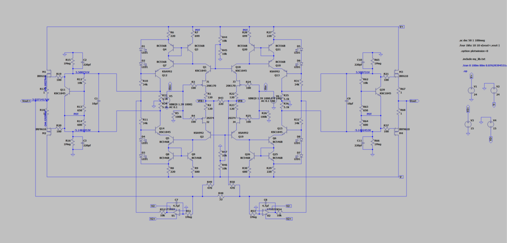
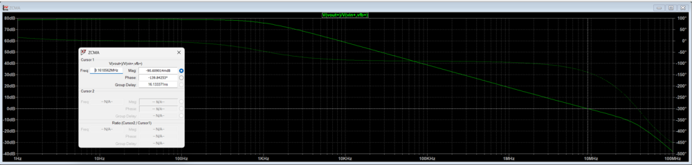
So I have spent the thanksgiving break playing around with ltspice, mainly wanted to do a 3-5W class A into 32 ohm balanced amp and started off with Kevin's CFA2/CFA3 design, and comes down to something like this, basically a slightly reduced CFA2: Just thought I want to put here for some input before trying to actually make it, which I'd much appreciate if any 🙂 I mainly have questions around: "floating tail" input (just like uberamp/preamp2025 input) instead of separate CCS (like dynalo/CFA3 input): Works in sim but in reality I don't know if I can just send feedback this way and make it fully differential with CF. When input is single ended where one side is ground, due to the feedback it seems to be amplifying the voltage disproportionally on two sides while overall differential gain is maintained. A problem or just an expected behavior that I can live with? (most of time I won't use single ended input) thermal: Is it essential to mount all the transistors in darlington triples to heatsink? Dissipation wise the inner ones don't really run all that hot. Im tempted to just mount the output pairs, planning to run them at around 200mA each phase margin: unsure if I'm measuring open loop gain correctly, am just doing vout / (vin - vfb) on one leg, where vfb is the feedback entry point. other suggestions?


-
Some if not all 6dj8/ecc88 datasheet has spec'ed max plate voltage at 130V, which the top tubes operate right around that range, I'd think e88cc/6922 is actually safer bet.
-
Anyone has some experience or tips simulating CFA3 SS mode in Ltspice? The transient analysis is barely moving for me, with or without servo, single ended or balanced input, not with arbitrarily large time step size neither, only way I tried to make run through is making open loop gain too low such that the close loop gain is no longer maintained by the ratio of the feedback resistors. I wonder if it's the cross feedback thing making it so slow. For reference CFA2 with current feedback runs fine; CFA3 open loop mode also runs fine, I'm getting gain of about 3.3 with gain resistors set to 10k || 1.9k, is this expected? (I use Jfet on the input) Thanks! Edit: Also attaching my ltspice sim file CFA3_ltspice.zip

-
I ended up using STP8NK80Z(FP) in place of those FQP ones and they work all good if that's what you asking? Should be available from major vendors still.
-
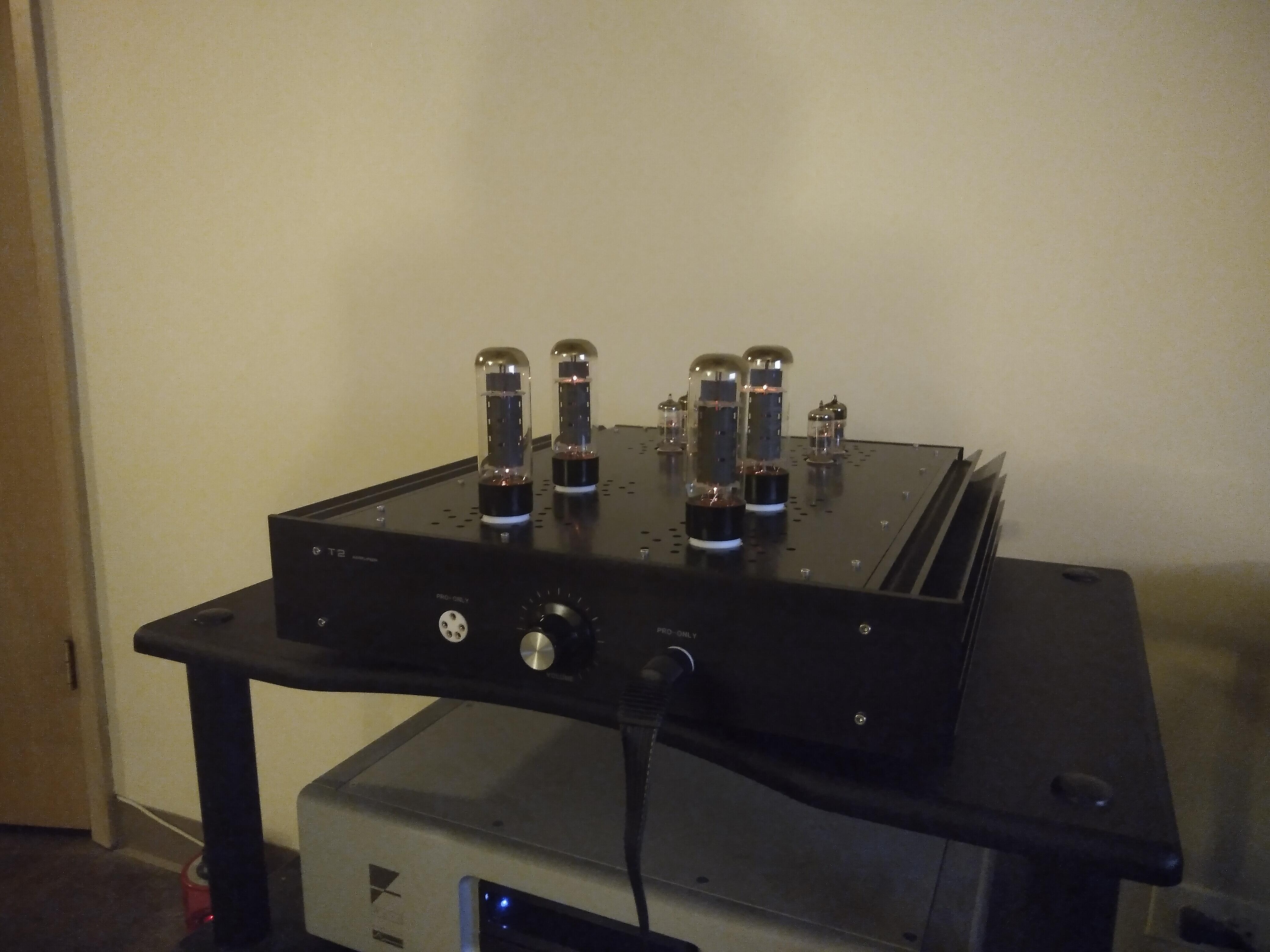
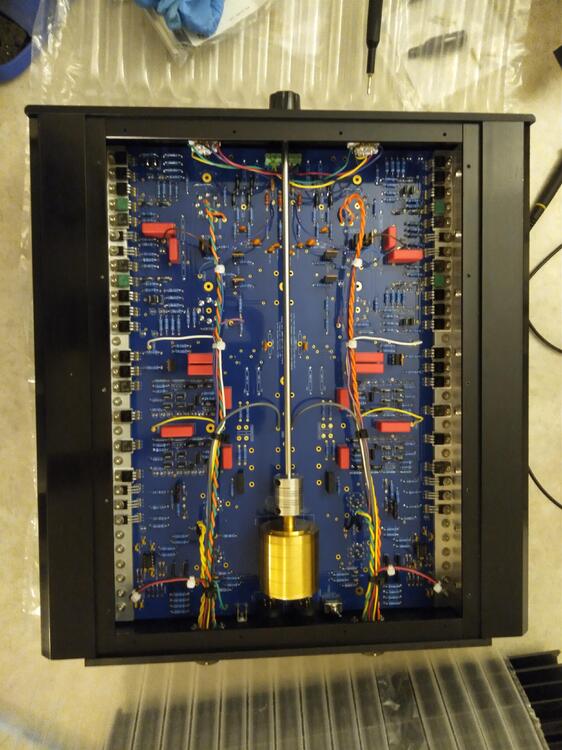
Very cool! How do you couple output stage to headphones, doesn't look like output transformers are used?
-
😃Was trying not to dump more flat-earth theories of T2 to the thread as I already did a bunch, but here are what (I think) my problems were: I didn't find the cause of the oscillations appeared at the output, but they are killed by upping the feedback caps from 5pf to 10pf. Some "AC components" I measured around output plate CCS might actually be oscillations excited by me sticking my handheld meter probes across floating nodes - I recall when I measure referencing ground it was different but better, but in the end when I probe with oscilloscope I see nothing there. When I trim both channels in place, turns out the 10M90S in -500V rail reached the boundary of current limiting so it's trying to sag and gives a sawtooth wave on that output rail voltage, hence appeared at the amp output. Lowering the current limiting resistors fixed it. When it comes to getting preamp tubes for T2, probably the most important and minimum requirement for the circuit to work is to have well-balanced triode sections for each individual tubes. Some permutations of the quad JJ tubes I got will give too much imbalance that is outside the correction range of the servo. Also I find my left channel having more tolerance on input tube mismatch for the servo to correct than the right channel - suppose the better matched the rest of the circuit is, the more tolerance on input tube mismatch you will get.
-
Fixed this amp a while back and been running it day to day ever since. So far everything works and seems to be stable, I finally get to enjoy the music coming out of it 🙂 It's definitely quite a thing building and troubleshooting it in the past 8 months or so, major lesson learned is that I could've gotten a scope on day 1 if I could turn back time. Many thanks to Kevin for providing such a design - the major heavy lifting of bringing back a great amp. Thanks to GeorgeP for supplying the hardware with all the building advices, or I would never have considered building one. And a special thank to Simmconn, who spent a lot of extra time not only helped me with diagnosing the issues, but also taught me a lot of the nuts and bolts about proper troubleshooting practices in general as well as demystifying the T2 circuit to me through patiently explaining. Of course there are a few more to mention, thanks to the folks out here who kindly helped me. It takes 10+ headcase veterans to help a newbie like me building a working T2 😄

-
@G600 I got my boards from GeorgeP and it should be whatever is the latest version of Kevin's design with original parts (as opposed to "modern version") Haven't got back to this thread for a while but I made some progress over the holiday time identifying the problem with a lot of help from simmconn as well as finally using a scope. -Balance: turns out by changing the permutation of my preamp tube locations in certain case I can get both channels balanced, likely some of my 6dj8 has better matched sections than others which were kicking the servo out of working range. -Offset: Replacing R73 with 10k pot I was able to trim out the remaining offset to near zero no problem. -Oscillation: quite possibly my last bit of problem, that I was observing low frequency (60-80Hz) sawtooth waves at all outputs. left-channel has seemingly matched waveforms on O+ and O- with hundreds of millivolts peak-to peak and right-channel has unmatched waveforms with one measures 1.42V pk-pk and the other much less and also reversed pattern along time axis. Slightly trimming the battery voltages doesn't seem to affect this behavior. When I got time again I will inspect things around the balance servo as well as breaking the loop to see if I can find out where it comes from. 🙂
-
Might have gotten a tiny bit more clue, been trying random things while waiting on a batch of K216/J79 replacement parts to arrive ($$$😢). I first tried replacing Q6/Q7, Q11/Q12 with KSA1156s, nothing changed, then I tried putting both C12/C13 in there instead of either, nothing changed (thus removed one again). Then I tried removing 5pf feedback caps across R78, R79: -Q33 still measures weird, plate CCS still violates Kirchhoff's law and are imbalanced, one J79 still has positive Vgs -Output offset went straight to -80V -Balance servo seems to be working in this case, with O+/O- within 1V difference and C/D being 1/10 of that. -Setting meter to AC measure mode and probe between O+ and ground, 18V @ 400kHz... O- doesn't give any significant reading, near 0V at near 0 frequency. So first of all it's possible that by removing these caps I just introduced new/worse problems. But it also makes some sense if oscillation is a part (if not all) of my original problem? if O+/O- were swinging some big time AC that would kinda explain why DC measure around CCS voltage doesn't check out, and why Q33 is having invalid Vbe from DC measure to be turned on yet Q32 still seems to be conducting fine? I certainly have absolute 0 knowledge on how to track down and troubleshoot stability issues, probably next step for me is just mess around with anything that have a time constant in it - capacitors, right after my previous battles against all diodes and resistors. I'm planning on trying: 1. Replace C1 with mica, I don't know what this RC network does but I seen other people built working T2 having mica cap there (could be wrong, only eyeballed from shape), and I used a film. 2. put 5pf feedback cap back and then try slightly higher values for comparison 3. maybe recap balance servo just in case I messed up some .47u/.1u values, hard to tell what I had there from looking Not too hopeful if this will fix anything but at least cure some boredom while waiting on those rare MOSFETs..
-
@simmconn Thanks for your explanation, once again 🙂 Sorry for the confusion and yes I meant D6/D7 (or D10/D11). Specifically, taking one side of CCS as an example: 1. V(D4) + V(D5) = 3.6V, Vbe(Q6) = 0.45V, V(R17) = 3.2V, this is all good. 2. Probe across R18-R20, all gives around 2.4V 3. Probe across B-E of Q8-Q10, all gives 0.57V 4. Probe across D6: 1.8V 5. Probe across D7: 0.7V (and probe D6, D7 together gives about 2.6V) D6, D7 look as bright, first round of trouble shooting I already replaced all LEDs and elevated them from contacting the board. Amp powered off and I diode test them they all fine with around 1.83V of Vf. So 2-5 makes no sense only thing looks ok is Vbe across C3675s. I will go ahead and check board connectivity tho. (Everything looks wrong when one probe is stick to O+?)