kevin gilmore
-
Posts
7,197 -
Joined
-
Last visited
-
Days Won
21


kevin gilmore's Achievements
Super Secret Ultra Gold Member (6/6)
2.5k
Reputation
-

and now for something completely different part 3
kevin gilmore replied to kevin gilmore's topic in Do It Yourself
many different versions. a couple of different sizes. i don't pay attention to such things. edit: here is list of boards by date 04/11/2015 05:43 AM 103,192 cfp2c.zip 04/11/2015 05:44 AM 104,260 cfp2cm.zip 05/29/2015 08:20 AM 462,573 cfp3rs.zip 08/09/2015 02:25 PM 156,813 cfp2dmt.zip 09/06/2015 07:45 AM 158,031 cfp2emt.zip 09/20/2015 04:37 PM 402,743 cfp3rss.zip 02/07/2016 11:11 AM 159,746 cfp2fmt.zip 02/28/2016 06:04 PM 159,406 cfp2gmt.zip 11/06/2017 07:26 PM 55,189 cfp2gmt - CADCAM.ZIP 11/30/2017 09:07 AM 66,091 cfp2hmt.zip 05/24/2020 11:29 AM 131,243 cfp3rssfixedss - CADCAM.ZIP 10/31/2021 07:41 AM 141,717 cfp3rssfixedsssw - CADCAM.ZIP 02/02/2022 06:19 AM 126,329 cfp3smt2 - CADCAM.ZIP 02/07/2022 06:54 AM 78,922 cfp3smt2splitpre - CADCAM.ZIP 02/07/2022 06:59 AM 63,188 cfp3smt2splitamp - CADCAM.ZIP 01/11/2023 08:18 AM 43,551 cfp3largeT.ZIP 08/05/2024 01:40 PM 125,671 cfp3smt2splitampdual2024-2-mosfetdualps - CADCAM.ZIP 12/28/2014 11:06 AM 77,647 cfa2.PDF 12/01/2017 08:48 AM 55,404 cfa2cmirror.PDF 05/24/2020 06:47 AM 53,387 cfa3production.PDF 07/23/2020 04:34 AM 69,492 cfa3productionss.PDF -
and now for something completely different part 3
kevin gilmore replied to kevin gilmore's topic in Do It Yourself
you mean this grossly overpriced piece of antique design. unbalanced and lots of feedback. clone boards were available somewhere at diy audio. chassis filled with many audiofool components. like bybee's and fancy caps. if 50 watts into 8 ohms is what you really want then build my pioneer a09 clone. lots better in many ways. i could publish pictures of the zahl boards, or the mass kobo. both of which are also grossly overpriced pieces of garbage.
-
Feliks Audio Bliss - so much stupidity...
kevin gilmore replied to spritzer's topic in Headphone Amplification
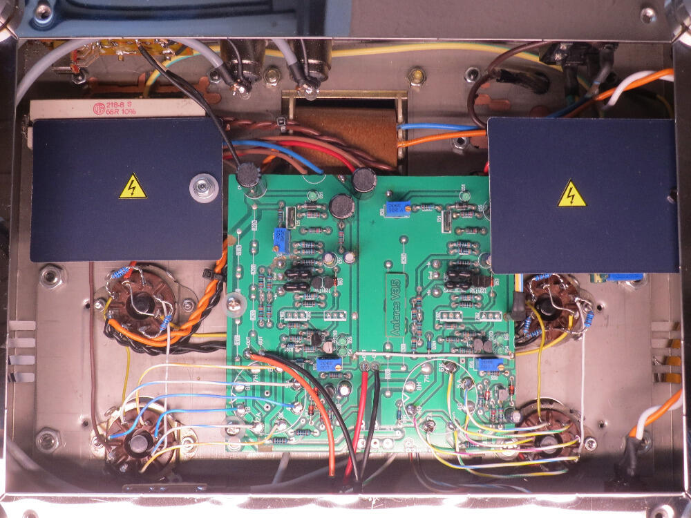
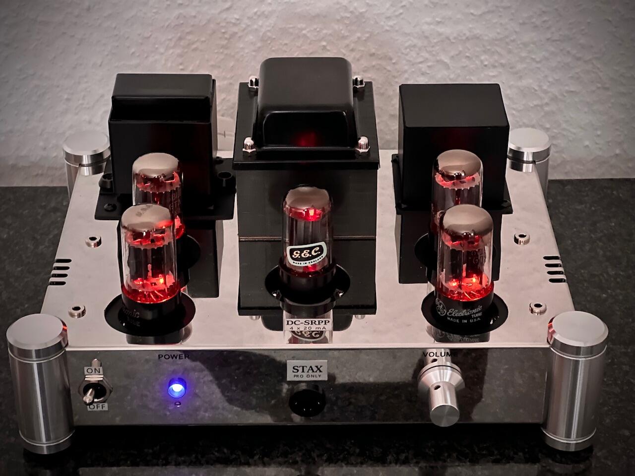
speaking of fucked, here is the latest highend.de stupidity. tube current source added to antares v3.5 board. 6sn7 has a max cathode to filament voltage of +/-100v which means that anything over 400vppss at the output is slowly destroying the current source tube. god damm how hard is it to read the 6sn7 datasheet. even worse the filaments of both current source tubes tied to the same transformer winding. sure does not look like srpp. how fucking stupid is this idiot. edit: this may have been done by someone else using the highend.de board.
-
Feliks Audio Bliss - so much stupidity...
kevin gilmore replied to spritzer's topic in Headphone Amplification
wiring the filaments together for the output tubes causes all sorts of trouble. essentially a differential output amplifier with no differential cathode resistors resulting in what should be infinite gain, except not. current sources for the output tubes sure seem to be a 6ca7 with a dn2540 or similar as a cascode current source. first time i have seen a tube and solid state together as a current source. and the input tubes wired as differential amplifiers do not have anywhere near enough gain should a chassis like this show up, i'm absolutely sure i can make a megatronxl custom board fit. edit: this is the current source CCS Circuits | Tubelab -
Feliks Audio Bliss - so much stupidity...
kevin gilmore replied to spritzer's topic in Headphone Amplification
1 metric boatload of labor goes into building stuff like this. And then making more and more. compared to a bunch of other stuff at this price level this is actually worth the asking price. No idea of performance. Highly similar to megatronxl. In 10 years when the electrolytics need replacing its going to be a multi day project. -
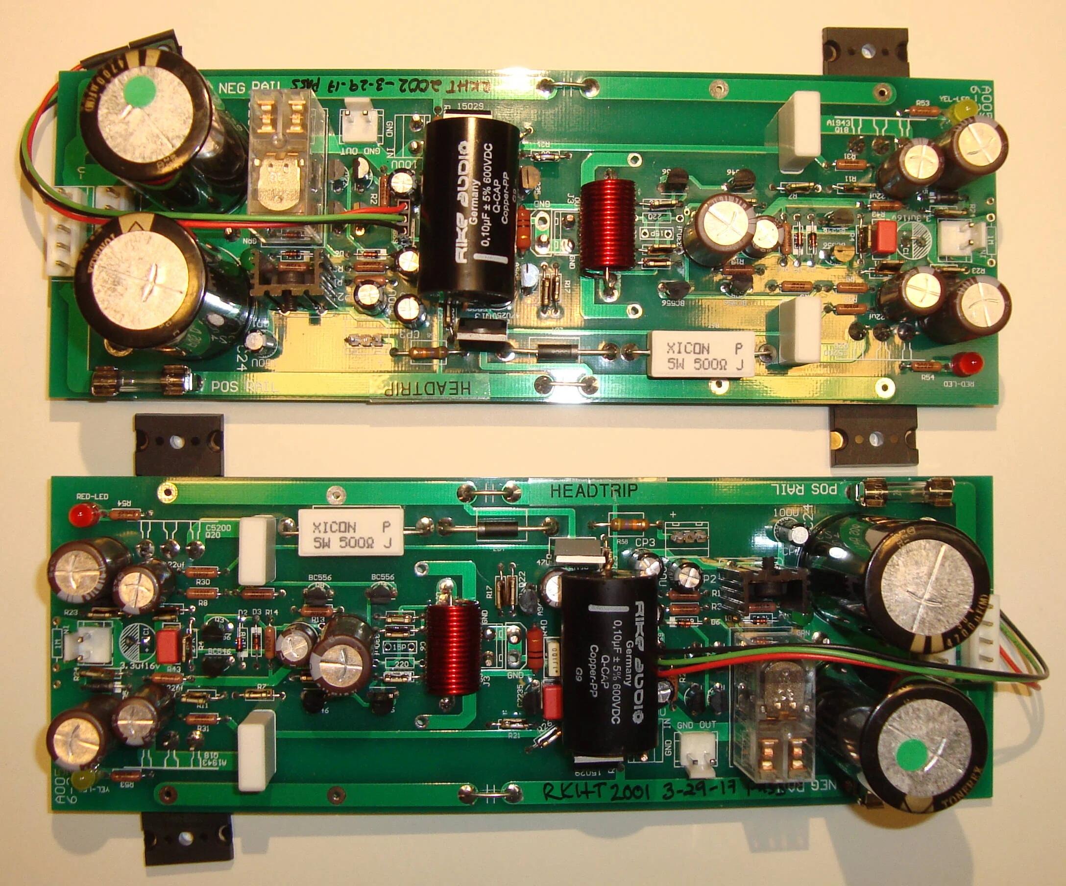
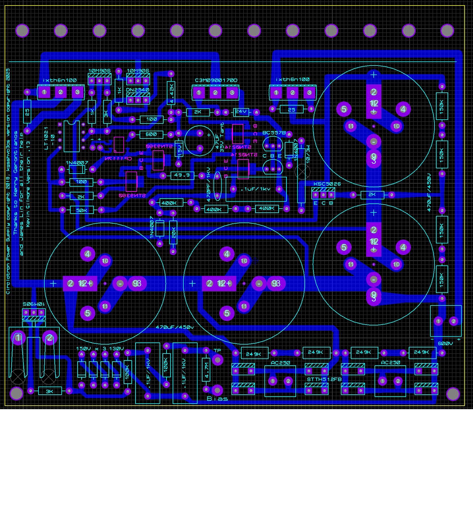
so the idea is to keep the voltage going to the 10m90s that drives the zener string between 600 and 900v. depending on voltage input, just a standard voltage doubler will push the voltage well above 1kv. and no reason for this. so in the very original spoilers, a pot was added to spoil some of the voltage that would normally have been generated by a standard doubler.
-
2 current sources now. 1 between unreg caps and passfet. other current source between regulated caps and output. kgsshv600vpowerv2 - CADCAM.ZIP circlotronpsupdated2cs.pdf
-
Megatron Electrostatic Headphone Amplifier
kevin gilmore replied to kevin gilmore's topic in Do It Yourself
i use the 47uf non polarized ceramic. performs better than the electrolytic, and lasts forever. -
edit: removed, looking at the wrong schematic.
-
board updated with extra diode. in the stax mafia google shares
-
the power of that part is 170mw. so the stn0214 should work. make sure the pinout is correct. mouser has thousands of ksc5026 in stock. the extra diode cannot hurt. not sure what it is supposed to do.
-
i know how the one error got there. the other errors may have been there for a very long time. will go and look at the original circlotron file later. updated schematic circlotronpsupdated.pdf
-
new board in the stax mafia google drive has the orientation of the ttc004b fixed. edit: current limiting on CS LED???
-
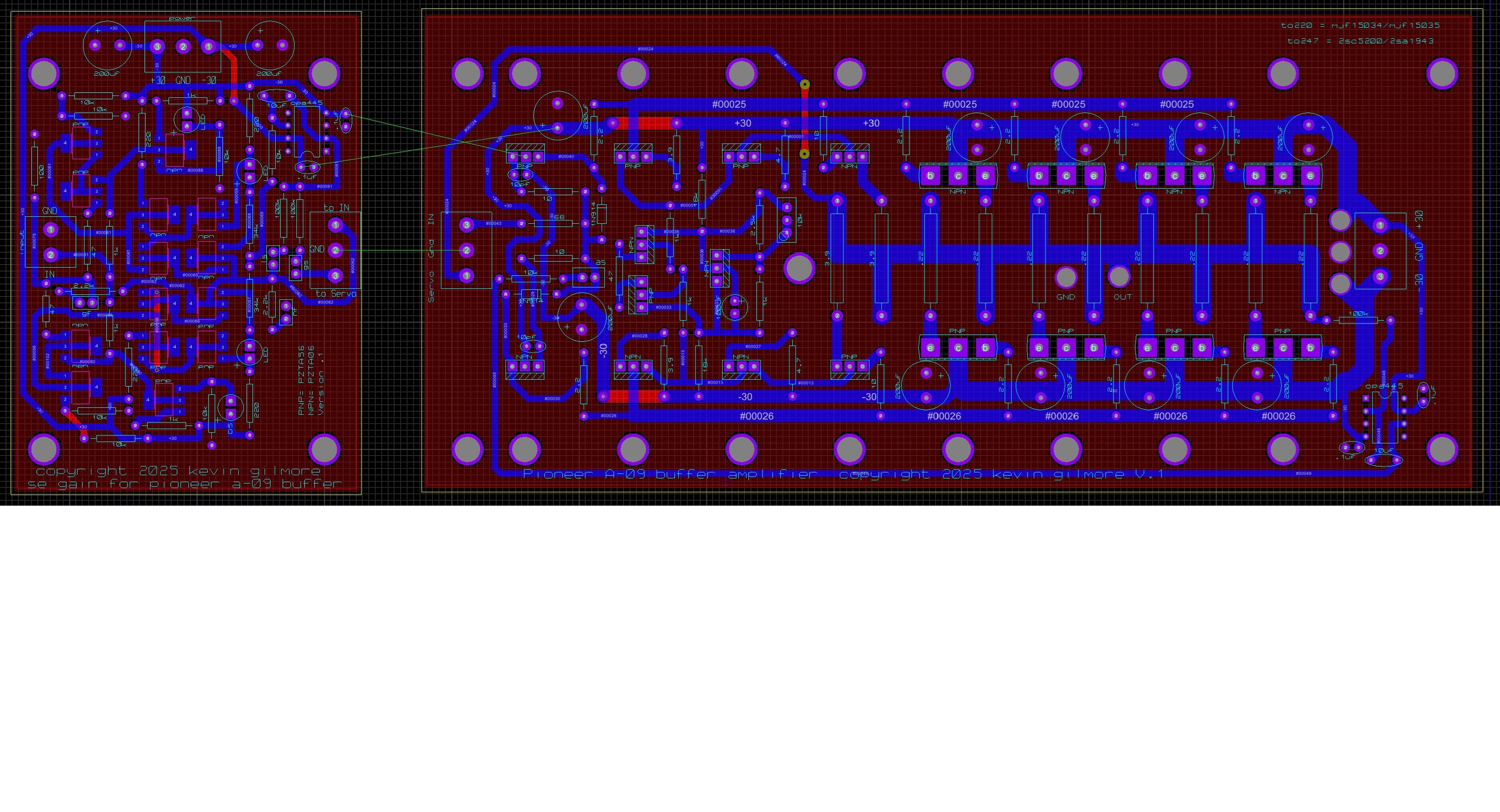
pioneer a09 clone zero feedback output buffer
kevin gilmore replied to kevin gilmore's topic in Do It Yourself
you can certainly set the bias at 2 amps, then into 8 ohms its 32 watts class A and the rest is class B or bridged 4x -
pioneer a09 clone zero feedback output buffer
kevin gilmore replied to kevin gilmore's topic in Do It Yourself
amp board for single ended. you can run this as low as +/-24v and as high as +/-40v pioneera09amp - CADCAM.ZIP pioneera09pre2gain - CADCAM.ZIP