-
Posts
14,452 -
Joined
-
Last visited
-
Days Won
22
Content Type
Profiles
Forums
Events
Posts posted by spritzer
-
-
I would guess so as well. There is not a whole lot of mass there so it would heat up quickly and no doubt damage the mylar. What a shame...
-
Soldering to the bias ring... not cool at all.
-
It is possible but you really have to take them out of the small housing and glue them together. This is due to the internal angle of the Sigma housing and how close the drivers sit to that side. Now doing this is very tricky but can be done.
-
1 hour ago, JimL said:
Yes, the joke at the time was the ultimate cheap Linn system was an LP12 into two strings attached to tin cans.
...so Grado's?

-
 2
2
-
 5
5
-
-
I'd like to know what they were smoking when doing that input trace... clearly needs more vias...

-
 1
1
-
-
I have one of those and it is ok but the screen is kinda bad and so is the resolution
-
The undersized 175K resistors aren't a great idea so I'd have 1/2W units there.
-
Do watch this then...
Amazon selling shit that will probably give people cancer.
-
 1
1
-
 1
1
-
 3
3
-
-
I see them on sale everywhere so I'm not surprised. Plus it sounds like shit and the build quality is even worse...
-
If you just want to have a simple test rig, the price here is hard to beat unless you can find a used Lambda for a similar amount. You would need to reterminate though or use an adapter.
The RR1 sounds a lot better though.
-
That's a hell of a deal and makes me mad knowing how much I paid for my set...

-
I've never seen anything off the shelf for sale but Vesper can make some for you:
https://vesperaudio.com/earpads
-
 1
1
-
-
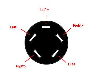
I can make an adapter no problem. I'd just have to dig mine out from storage and look at the pinout. I know I bought some extra sockets for these when I made my adapter.
-
 1
1
-
-
I will be getting both sets of pads and naturally... I take everything apart so expect pics. 🙂
No doubt the normal bias SR-X is a bit bright as they were tuned like that. Stax wanted to bleed off a lot of the bass so the end result is a bright set. My point was more with the importance of the pads as they matter a lot with the close proximity of the drivers. Also when they have arc'ed...they get even brighter.
-
 7
7
-
-
With the SR-X series the pads make or break them. The current pads Stax stock are actually SR-30 units as the originals haven't been available for a long time.
Now for the topic at hand, I have one of these incoming so it will be fun to play with. 🙂
-
 4
4
-
-
With the SB boxes there is a third transformer inside the unit which taps off the HV side of the audio units and further steps up the voltage. That is then fed into a voltage limited voltage multiplier which generates the bias voltage.
With the AC units they feed directly into the bias supply multiplier which isn't very safe these days.
-
So here I was modding a SRM-006tS to a CCS and noticed this:
That is the R+ output and notice the 3 lines coming off it, one going to the feedback, one going to the output resistor and one... going to the other side of the output resistor...

One has to wonder just how many of these they have shipped like this?
In other news, it was fun converting an original T1 and and this one at the same time. 30 years apart and almost exactly the same...
-
 4
4
-
 1
1
-
 1
1
-
-
Crap, I missed that sale as I would have bought 10 sets...

I think the dynamic Koss set was A/250 but I could be wrong
-
Currently, yes. Well if these are even still sold which is rather hard to confirm. They do sound like crap though....
-
3M has some great stuff that actually works. The name escapes me though....
-
Well the cause is simple, bio-degradable adhesive which is just terrible and the solution isn't so simple...find something better.

-
It's been a while but since the Exstata is based on the Stax SRM-1 Mk2 it should just be a balance and offset adjustment. The pots should be matched on the PCB so for balance, put the probes between + and - of each channel and adjust to 0VDC. For offset ground the black probe while the red is in the + output for each channel and adjust to 0VDC.

-
 1
1
-
 1
1
-
-
Yeah, that works just fine.
-
It's the same headband as the SR-007 so two screws on each side that secures it. Be careful, those are JIS screws so pretty easy to strip with other drivers.
Also, anybody want to see the most disgusting SR-007's in the world?
https://page.auctions.yahoo.co.jp/jp/auction/s702210988
Yeah...those early ones don't hold up.
-
 2
2
-


The Headcase Stax thread
in Headphones
Posted
You can get a clean bench which are for instance used to repair hard drives and other sensitive equipment.