spritzer
High Rollers
-
Joined
-
Last visited
Everything posted by spritzer
-
Better yet... Single Power ES-1 board!! Seriously though, as fucked as the ES-1 and ES-2 were... there was less wrong with the actual circuit than this pile of fail. Let's put build quality aside, the permanent 100V offset, non floating heaters chewing up tubes and some other "minor" issues... they did produce enough volume for a normal listening session.
-
Given the number of windings there, it has to be at least a couple of transformers. That is also clearly a Toroidy transformer, based on the color of the wires, and they never do tall transformers, they always just get larger and larger in diameter. That means it could just be transformers in there.
-
Yeah I agree but one possible major, major issue... one filament supply per channel for a balanced amp. These are no indirectly heated tubes... the filament supply is the bloody cathode.
-
They are very different headphones and the ES-2a easily beats in terms of price but I'd lean more towards the 009D in terms of raw performance. The 009D is really growing on me and what amazes me is how Stax can release crap like the X9000 and the 007S and then this... Both the X9000 and 007S are headphones I'd never listen to for fun while I've been logging a lot of hours on the 009D.
-
Look like 1544's to me too and that's not good given the gain is a quarter of what it should be. It is just me or are the output tubes AC heated? Those wires seem to run right to the transformer...
-
There is not enough detail to retrace anything or know what is on the heatsinks but from a build quality standpoint... this is very dire. One thing springs to mind... where is the power supply? Seriously, where is it? Also signal wires make no sense, that bias supply has be scratching my head, that's not how you do point to point wiring and servicing this would be an absolute nightmare. Does anybody see 20k€ here?
-
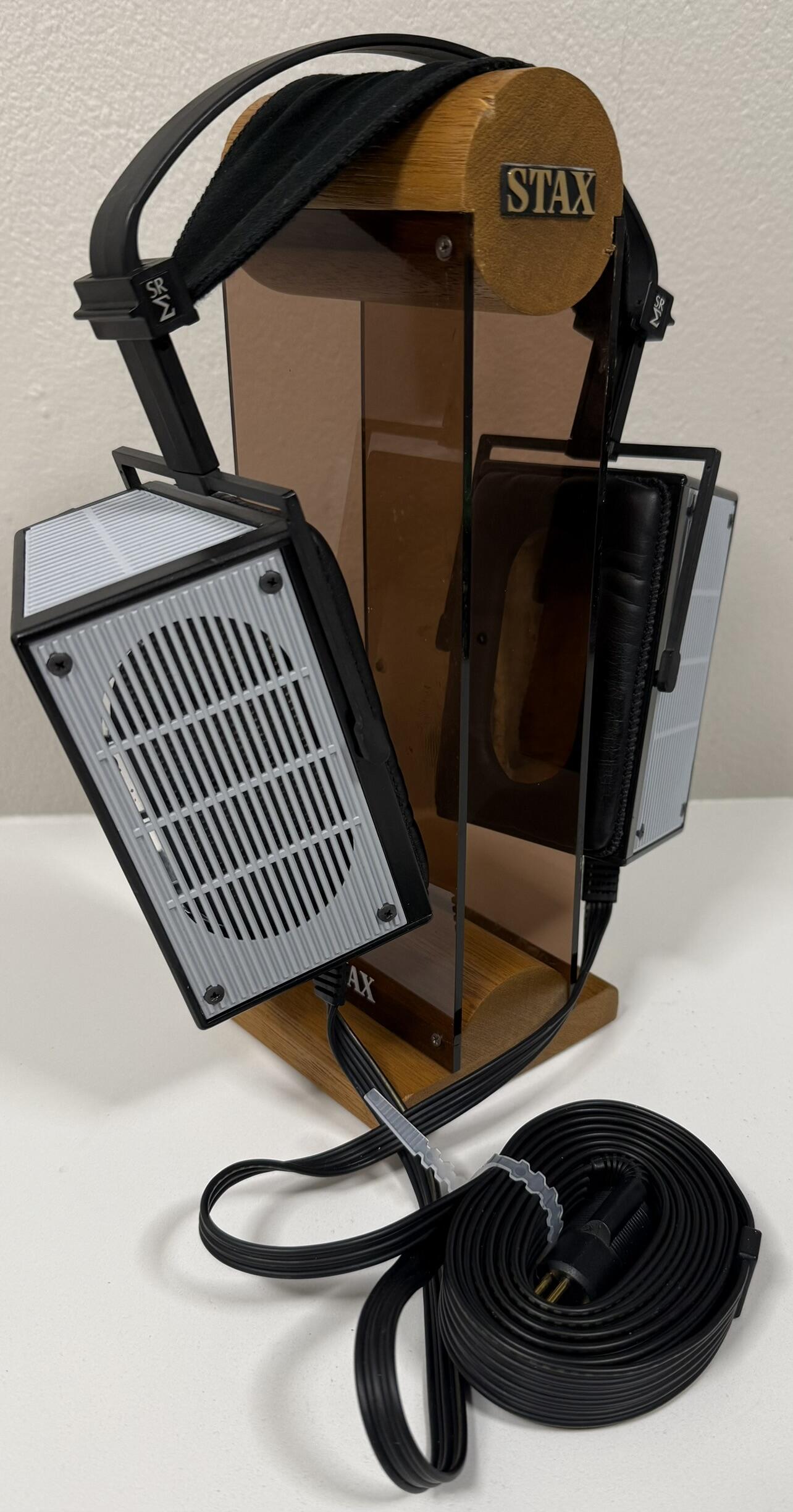
I've going over my collection, filling in any items I'm missing, I felt I really should have a modernized version of the Sigma. I came across a rather abused normal bias set which needed new drivers but wanted to try something different... so here is the SR-Sigma 507: The housing was very discolored so I wanted to try my hand at painting it. The frame was primed and painted satin black but I left all of the other parts in the primer color. The plan was to make them gloss white but this looked too cool so this is how they stayed. The drivers and cable are from a 507 so it took a lot of work to get this right. The drivers are in the cage that Stax introduced with the x07 series so I glued the drivers and fitted spare metal grills to them. In terms of sound, this is the best Sigma I've ever heard. The bass is overblown, as is always the case with Sigma's, but it has some real power to it and is more controlled than every other I've heard. The top end is nice and clean and the midrange is just sublime. A fun addition to the collection.

-
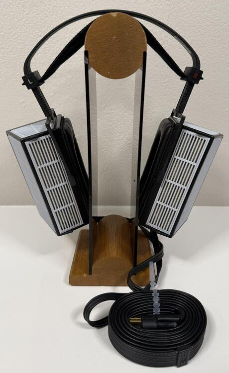
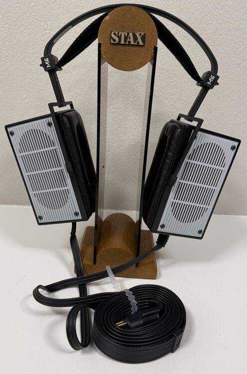
Figured I'd post this picture here as well as in the Stax thread, MA-009 vs SR-009D I've just been on holiday so no work on this project but I'll probably make some new diaphragms for the MA-009 soon. The ones in there are just too unstable, any major airpressure and they just stick to the stators.

-
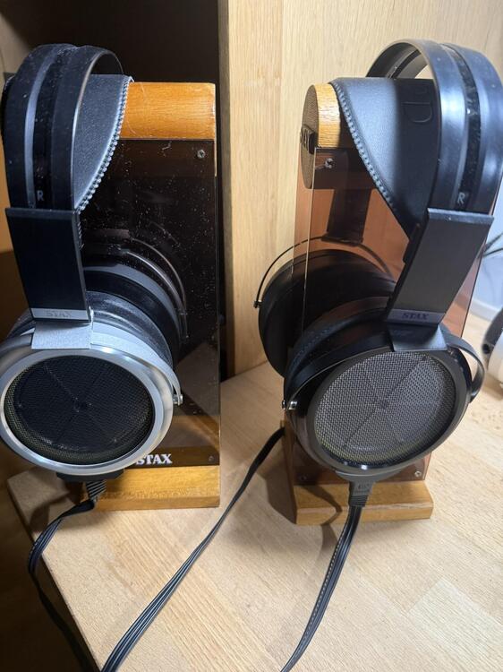
Well I've been away and a certain SR-009D showed up in the meantime... Sorry for the crap picture but I've only had a couple of hours with them and I should have been in bed an hour ago... First impressions, I like the color but it's clear that Stax have cheaped out with one of those surface treatments that are so popular in China. Nothing as nice as the 009BK here, it's that matt but shiny black except in the grove on the back. It's okey but we are clearly seeing production moving away from Japan here of crucial parts. Same is true for the earpads, very different from regular 009 pads and the smell and feel is identical to the various earpads I've been buying from China. Nothing wrong with that really... if they didn't resell the 10$ pads at 200$. They are also odd as they don't seem to fit nicely on the headphones but feel nice, much better than the 007S trash pads. They are similar to the Omega pads in some ways, large opening and pretty thin. The headpad seems also different from the older models so likely a new supplier there too. Same basic thin pad design though but a bit wider overall compared to the L500 part I have on the MA-009 in the picture. Same cable as the SR-X1 and the 007S. I'm not in Japan so I'm not getting the shorter cable as instead of throwing them into the boxes, Stax wants you to send in for them, in Japan only. Gotta love companies living in the 70's. As for the sound... I was expecting to hate them but no... these are the first 009's that aren't way too colored for their own good. For the most part, they are easy to live with with plenty of bass and presence. Maybe a tad dull and uninvolving at times but still easy to get long with. Now they are not perfect, there is a distinct "bass drum" resonance on many tracks and some certain ranges make them way too shouty in the midrange but it's far from as bad the originals or what the hell the 009S was. Nice controlled soundstage with some depth to it, good extension on both ends of the spectrum so yeah... I'm pleasantly surprised. I haven't detected any of the serious driver resonance issues as with the 007S either. Only a couple of hours with them but some volume matched comparisons with the MA-009, I prefer the fuller sound of the latter but it's not a long way off. I do feel the irony of me finally tackling the long planned project of fixing the 009's, only with Stax releasing a new version which doesn't suck like the older ones at the same time. Still, this is good move in general and at present I'd recommend these over the 007S and the X9000, let alone the older 009 models.
-
Dear god this is bad... seriously, what the actual fuck. So we have tetrodes... feeding triodes into beam pentodes? Or they stole the Megatron output stage and picked the worst possible input stage on the planet? Now where to start, 20k€ for an amp with a quarter of the gain it should have. Trash input tubes, adjustable bias to guarantee somebody blows up their headphones trying to compensate for the low gain. I can't wait for the internal pics from China to showcase what a clusterfuck this is.
-
I've been following along with it utter crap springs to mind. The amplifier is a Stax SRM-1 Mk2 with some cobbled together power supply. I have no idea what output devices are being used but they look modern so holy Cob batman... yeah... As for the headphones, I've not heard anything good about them. Going by his speakers, this is amateur hour. No dust covers, the bias supplies in the speakers are those 3$ modules from China which ring like mad and spew out trash... for what 100k$?
-
This is the statement, translated: ...so I don't think they are going to replace them. The Shure KSE's are also discontinued with no replacements that I've heard of.
-
I truly don't get why Stax didn't just modernize the SRM-002. Make it all SMD, add a couple of li-ion cells, a bluetooth receiver and just profit. Make it in a nice plastic housing with both a 5 pin output and the 002 plug. No stupid USB input which just complicates everything.
-
Hehe, I should have been more specific but they have stopped production of them. No replacement for the SRS-002 as they hope people will use the SR-003Mk2 with the D-10. That makes 30 years of continued production of the portable system coming to a close.
-
In other Stax news, the SR-009S and SRS-002 are both dead now.
-
There is no way to do that, that would have to be awfully thing metal and how would it be attached. If you attached it on the diaphragm side then it would short out the driver and it would simply cause more reflections on the other side
-
The drivers are the same except new diaphragms and naturally new diaphragm holders for both dust covers and the main films. The material, tension, treatment and even the direction of the tension is all crucial to how the headphones sound. Still with the stock housings and stators, there is only so much that can be done. Now sure what green PCB you are referring to though? There is nothing like that in the stock headphones.
-
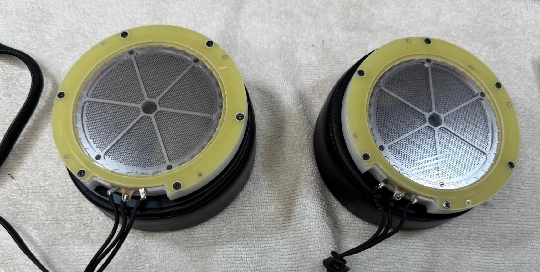
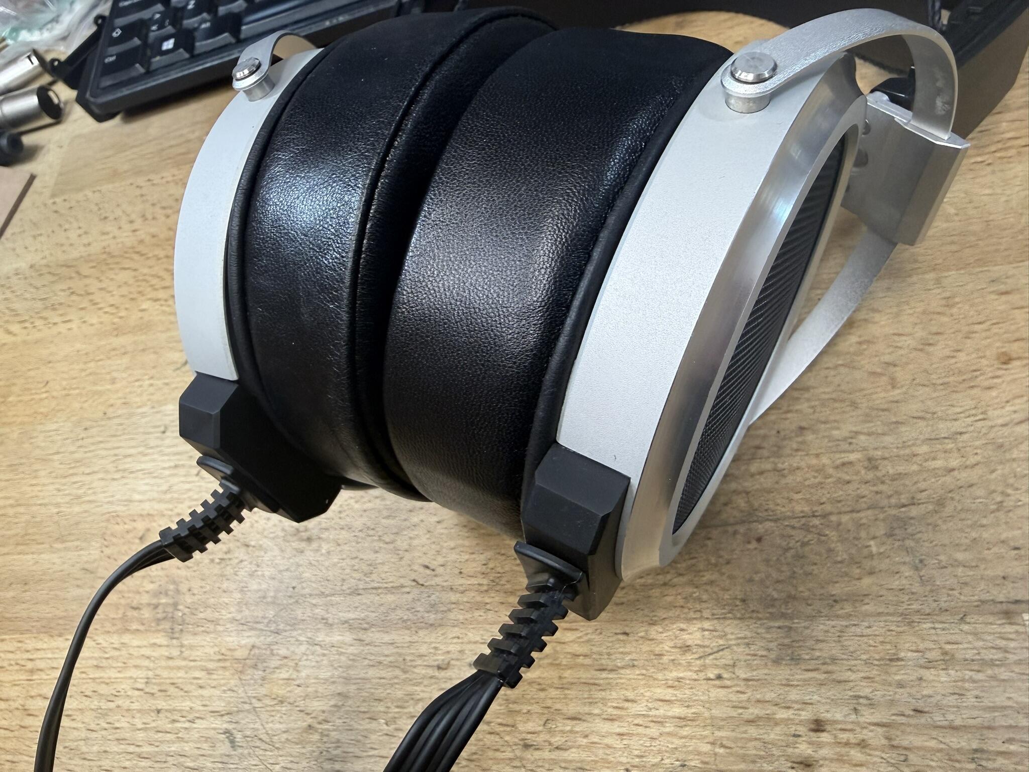
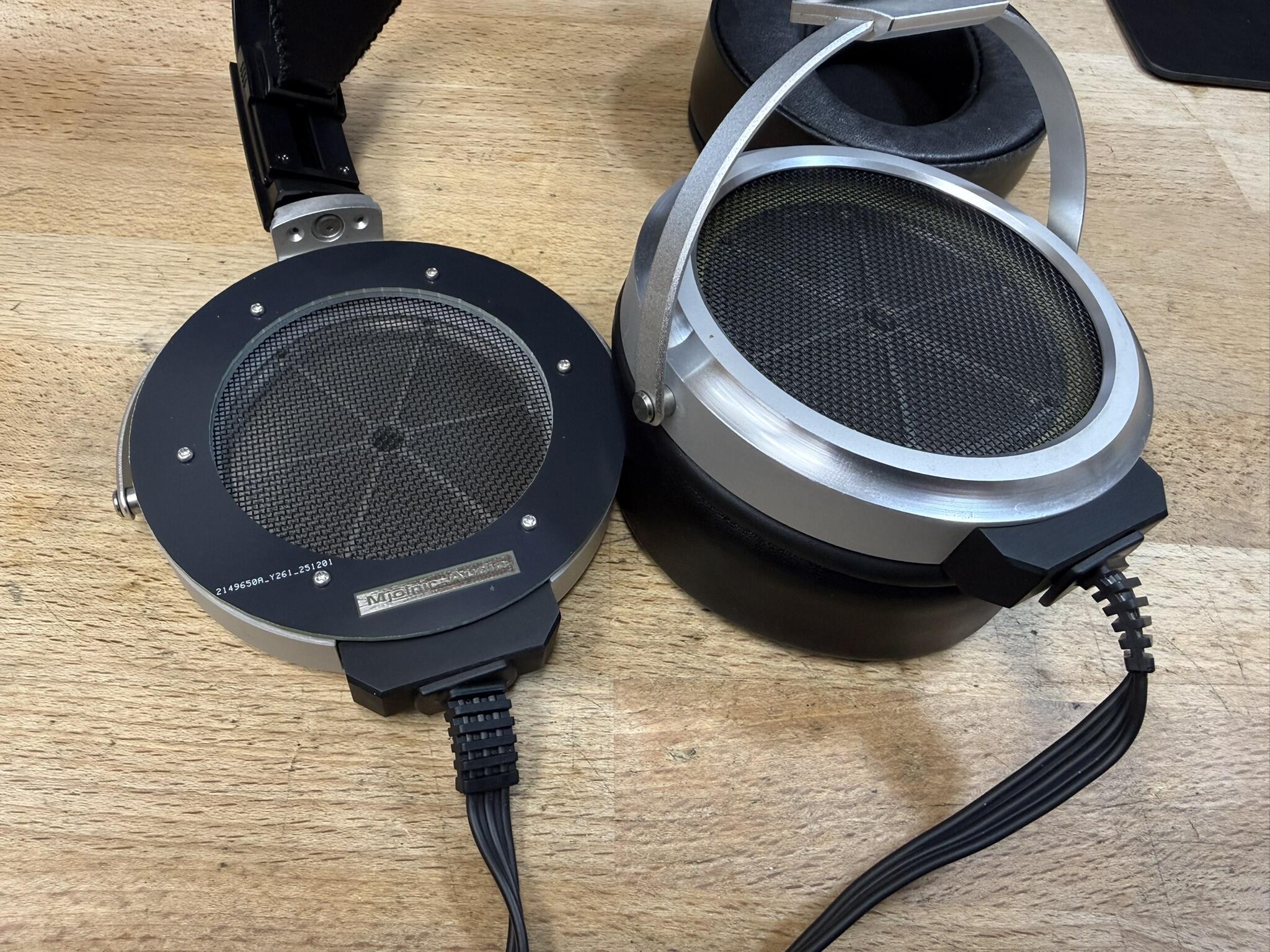
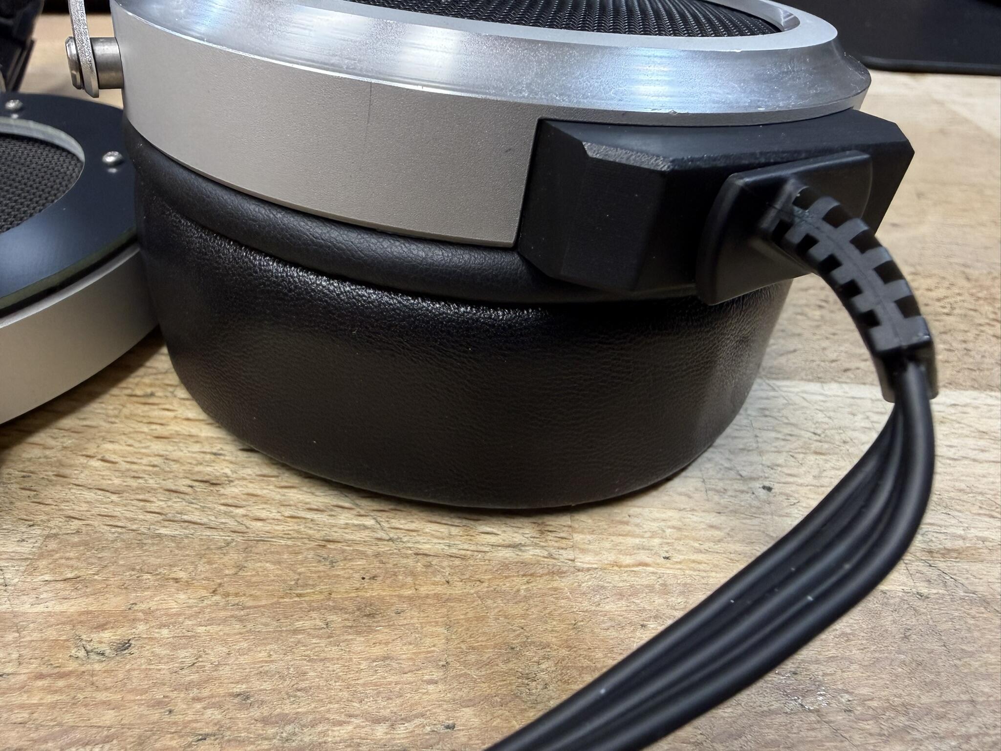
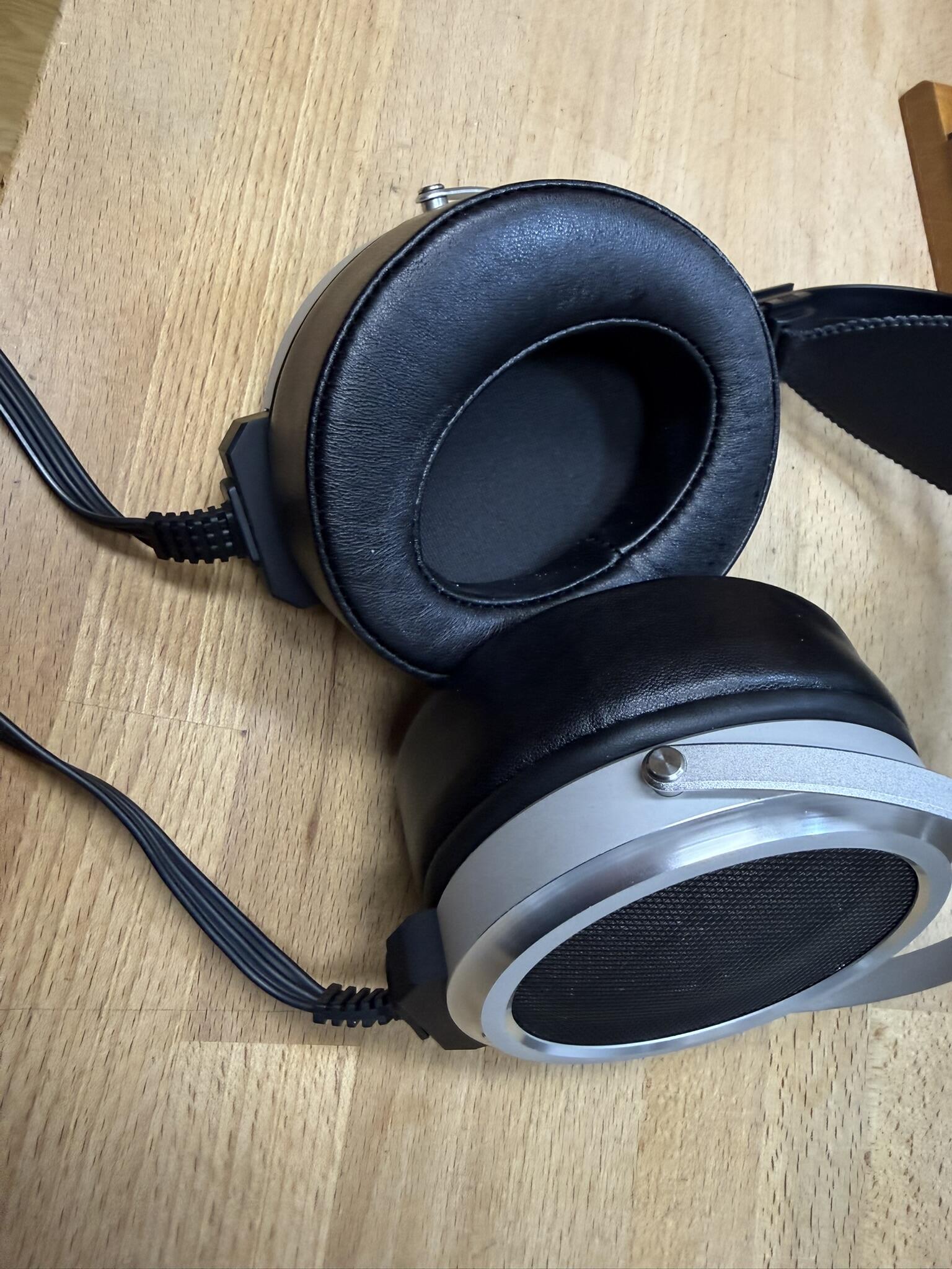
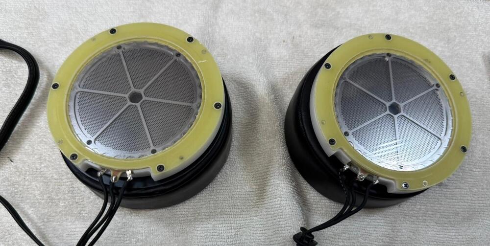
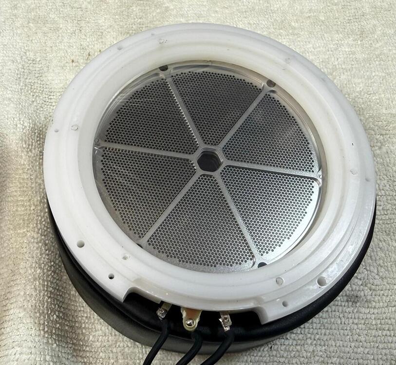
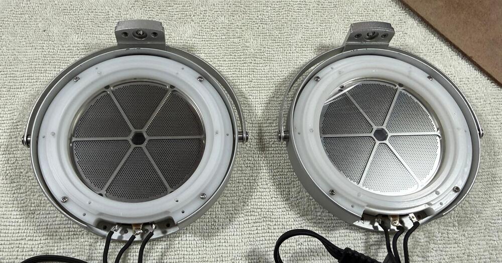
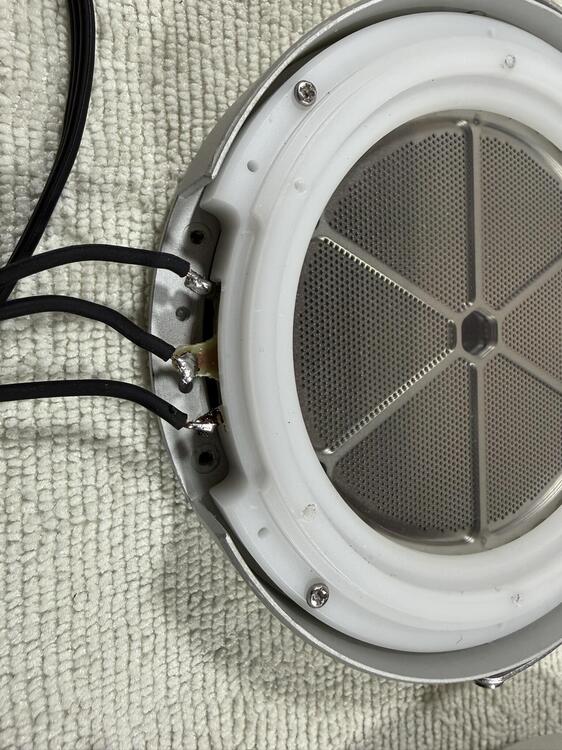
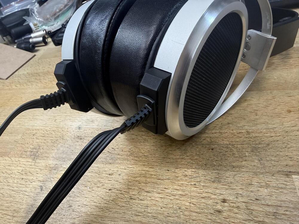
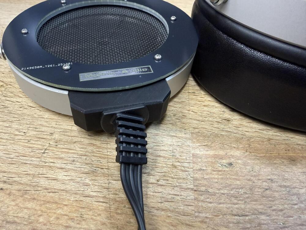
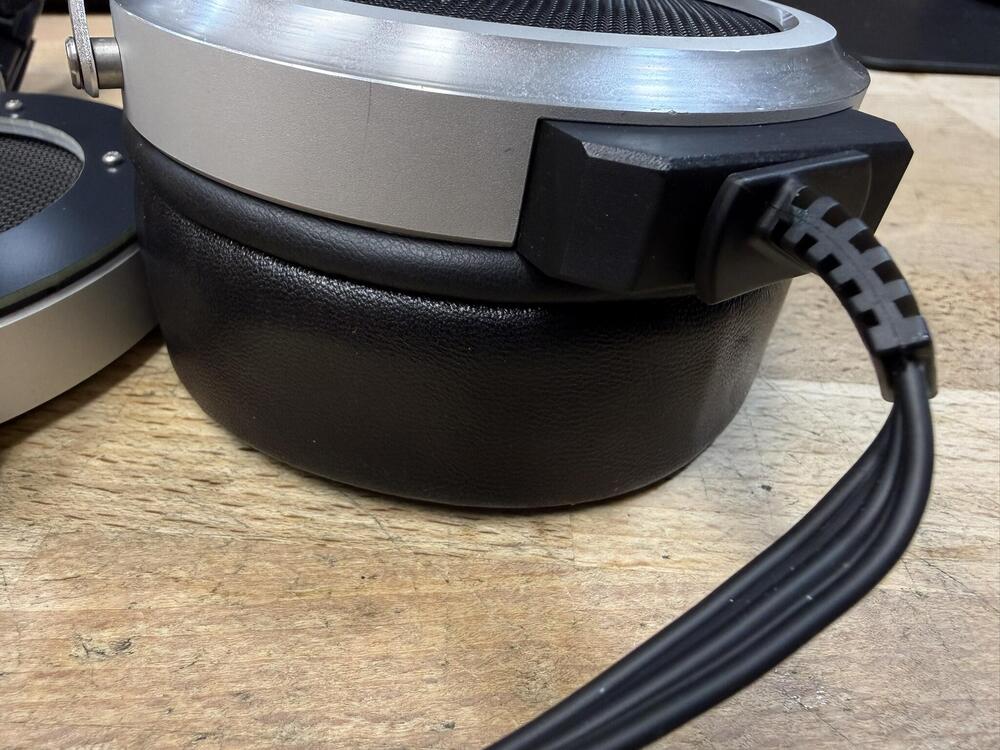
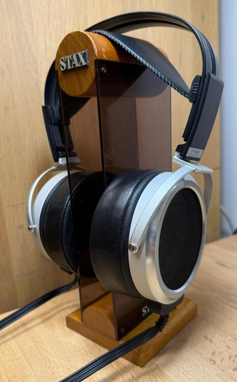
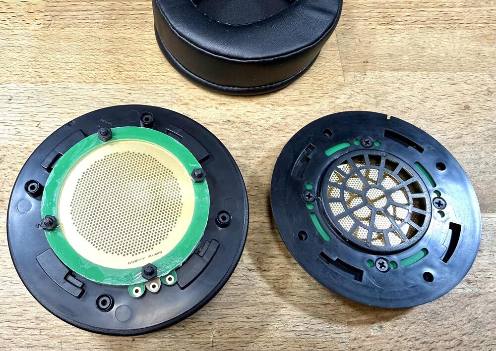
Now it shouldn't come as a massive shock to anybody but I'm not much of a SR-009 fan. From day 1 they always sounded messed up to me and the BK and S didn't really make it any better, even a bit worse with the 009S. To this day I have only one 009BK (as it is a limited edition) in my collection and one regular 009 that showed up here randomly and was a stark improvement over all the other sets I've owned. No idea why those sound different but better not mess with them. Now the plan was always to do something with the 009's to improve them but there was always something better to do. Well with surgery pending a couple of months ago, I finally had time to do something not too taxing. First off I needed a donor set and here is where that came in: I got these three years ago and they just sat there in a box. Too many parts missing with no spares available, three out of the four dust covers were trashed and I took off the arc to rescue another 009... so a pile of parts with fucked up drivers. The plan forward was clear though, the drivers needed new dust covers, new diaphragms, a way to mount the cable and finally some way to attach the earpads which wasn't 009 levels of stupid. Now none of those parts could be reused or they simply weren't there so time to do some designing. I still suck at 3D design but practice makes perfect... or it should in theory. Now first off, dust covers and diaphragm holders. These are easy to do as PCB's but materials, thickness, films used etc. are all large variables. Here are my first drivers, actually using the third batch of diaphragms as I slightly tweaked the dimensions once I started test fitting: Those familiar with the stock drivers might spot the bias connection is very different. I had to spend a lot of time cleaning the stock drivers, as they had been open for who knows how long, but this first test was successful. Fully balanced drivers and no noises from them at all so they are as clean as I can get them. The dust covers are 2um mylar-C, just lightly stretched (hence the slight lines visible) and the main diaphragms are also fairly loosely stretched 2um mylar-C, then heat treated and given a coat of fabric softener. The drivers are easy to align but one major part of this project is to find all the correct o-rings used to assemble these and in the right grade. When I had waited a month for a large shipment just for the one size I needed to not show, I even bought some stupid expensive examples locally. That got me here: All new screws used to get the drivers into the housings. You can see how beat up the aluminum housings are but hey, fine for a project like this. Now there was the next difficult bit, the cable entry: On the stock set it is a plastic guide which sits in those holes, the cable fits in that and the whole assemble is screwed down. Now the stock cable I had was not perfect so instead of making my own version of that... I just used a standard Lambda cable. A L500 was going to die for this set anyway (as I needed the arc) so why not use that cable. Here is my solution for that: This is 3D resin printed and is the second revision. First was just to check for hole size, alignment and if it was fouling on anything but it was way too shallow. This version still had to be sanded a tiny bit but it fits nicely. I did make a 3rd and 4th version which is incoming to clean up the design a bit and give me some more internal room. The earpads above are simply stuck on with some blutack so more on that... For the earpad mounting, there two problems there really. None of mounting hardware was included and anybody who had changed the 009 pads knows just how fucking stupid that mounting setup is. I also wanted to use non Stax earpads (not paying 300$+ for pleather crap) so here is what I came up with: Same idea really but I added a spacer between the plate and the driver housing so there is room to slide the lip of the earpads underneath it. The two layers of the PCB sandwich are visible there (along with the production number as I forgot to have it removed) and it works nicely. I could have made this from aluminum but it wouldn't have cost roughly 4$ then... This is the fitment with some random test earpads and standard 1.6mm PCB's. Works just fine and I can't find any issues with baffle seal... quite the contrary really. So here we are, the MA-009 This set of earpads has already been replaced and it takes a matter of seconds to swap them over. What a novel feature... Now what was the true goal for all of this, well besides having some fun doing something new... make a set of 009's I would actually want to sit down and listen to. Now this project is far from over but here is something novel... a SR-009 that has some actual bass output. They are still forward sounding but it has been diminished by a large extent. I can use these for hours quite happily, even at my usually higher volume levels. The decision to use 2um mylar was to try and tame that forward edge and it has been partially successful. A stock set of 009's is terrible on most music I try them with, this one is mostly good with just some tracks which show how bad that stator design really is. There is this slight forward sheen over everything and it simply has to be the stators as the rest of the headphones has so much in common with the 007 overall design. Now the major issue is driver stability as the left diaphragm really likes to get stuck to the stators and I have to open up the driver to get is back on song. I might have gone too far in sealing them up but I wanted some bass dammit!! I will make some more test diaphragms and see if I can make some which can handle the pressure of going on the head energized while giving the sound I want. For now I'll just use this pile of parts to make some music... So to end off... if anybody has a set of 009's with blown drivers that are collecting dust... hit me up and I might want to buy them.


-
A SRM212 with one of those USB to barrell jack adapters and run it off a normal USB power bank. 4W should be just fine of a 2A output.
-
Driver size has nothing to do with performance over a certain threshold (say 60mm), I'd even say it makes a lot of parameters much worse. It's more down to the structure design, stator design and diaphragm properties. Stax are failing at all of these BTW... it's all bad. It seems there is very little interest in the 009D, goes to show with the stupid promotion they have running with them. Buy a set in December, mail them a registration paper (as in by post) and they will send you a 1.5m cable. They say it is the silver plated one so why include that and not the OFC as is stock with the phones. Makes no sense.
-
Same OFC cable I can see and rather underwhelming overall. I didn't bother ordering one but I might if there are any discounts to be had. I have my SR-009 with new diaphragms up and running and it is quite interesting just how badly designed those stators are. Even with new diaphragms tuned to be anything but bright... they are still far too bright. Still far better than the stock unit and tolerable for most tracks... ohhh and they actually have bass now. Odd for the 009's...
-
Hehe, I don't think I'll ever be there but I have a lot of fun messing with this stuff. I might open this up as a DIY project if anybody is interested as this isn't all that hard to do and no bad chemicals are used. While on the subject, I finally got the last parts to get my reclaimed SR-009 drivers up and running with new diaphragms and dust covers. I skipped straight to the Mk2 version of the main diaphragm rings and they are now sitting on my head with nothing holding the earpads on them and cables just dangling off. I keep reiterating the new cable entry design so I won't post pics until the system is all complete.
-
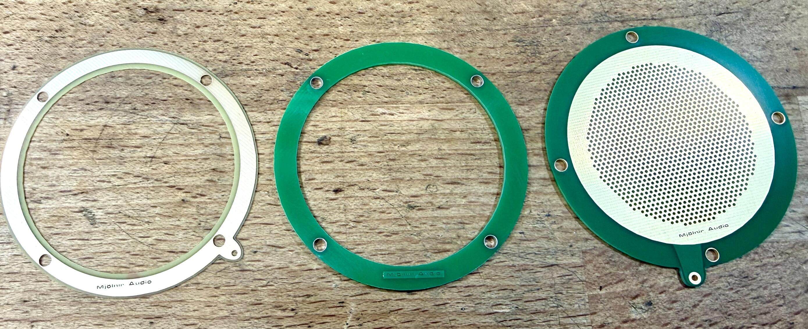
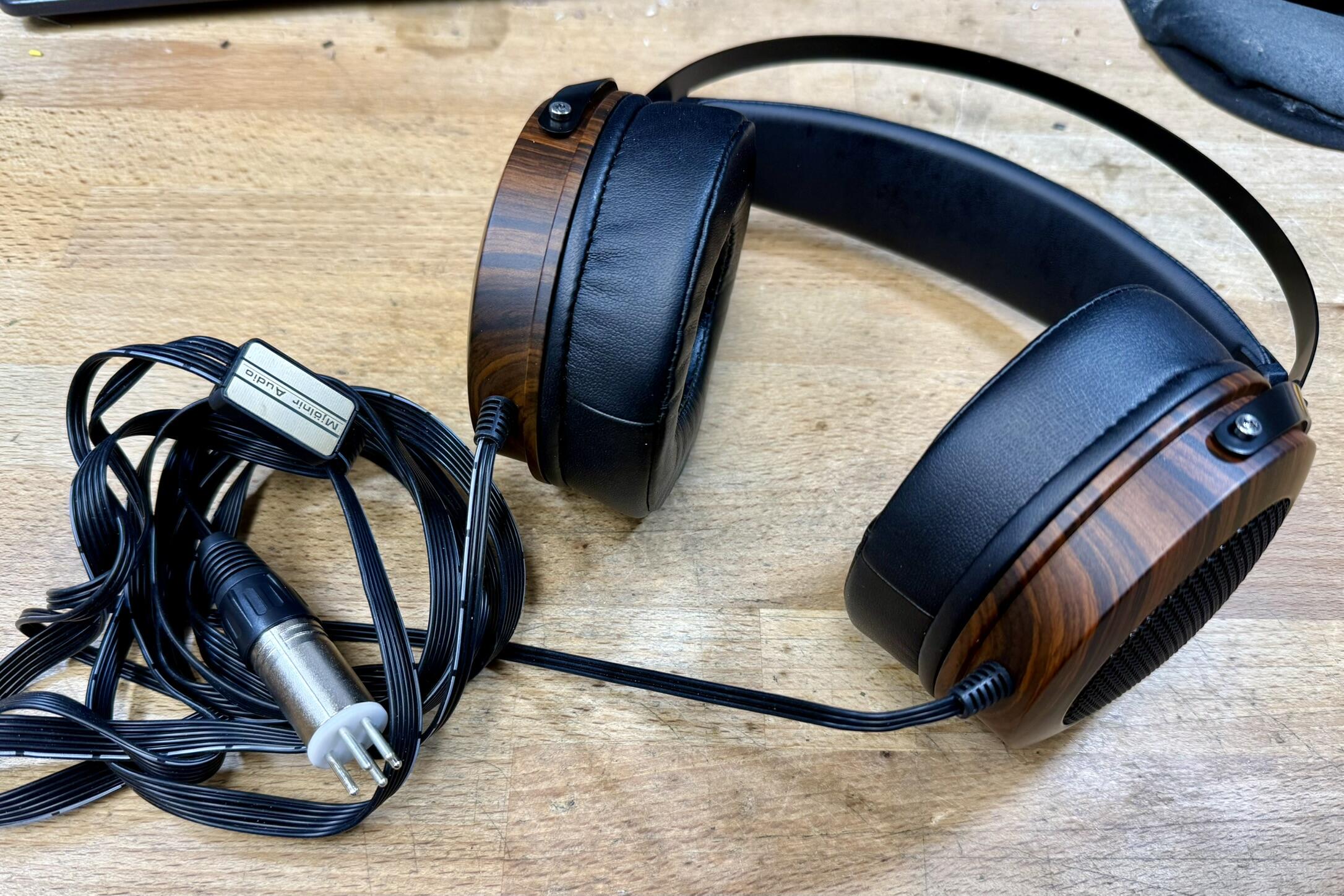
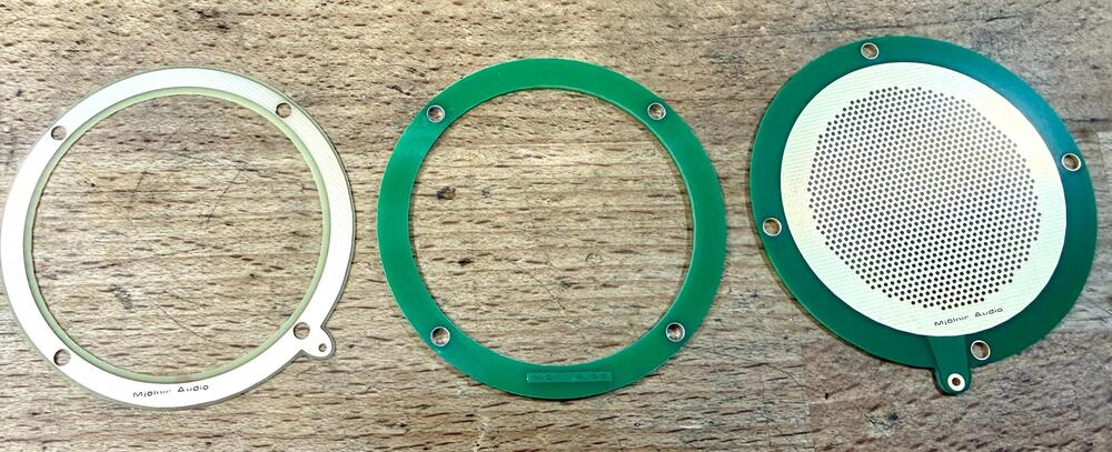
Finally the PCB's arrived for the Kiwi Ears headphone drivers: Just three different PCB's needed, on the left is the diaphragm ring which is a 0.6mm pcb but with no solder mask so it is actually 0.51mm. This has to be ENIG to make it completely flat but most fabs require that anyway. Film is 2um mylar-c as that is so simple to get and relatively easy to work with. In the middle is the dust cover holder/spacer. I made this 1.6mm thick as that way it clears the stock lip on the baffle that was around the dynamic driver. I used the first one as spacer and then stacked up the driver sandwich. For the dust covers I used the same mylar as the diaphragms but not stretched as much Finally the stators, 1mm ENIG pcb's and this is the outer side with the inner side having a smaller active area, aka like the SR-007. Holes are a bit less than 1mm but that can easily be altered for another run. Here they are assembled with the only alterations to the baffle where I counter sunk the mounting screws. There were just the three holes there in a row and with the earpad mounting plate being flush to this, it had to be done. One second with a counter sunk bit will do this as this is nasty, cheap ABS plastic. Here they are assembled. Only mods to the chassis is that I enlarged the two holes there are on each side (cable entry and a port on top) to 5mm so the strain relief would fit and the solid plastic plug I glued into where the port is. The cable is the 6 core silicone wire that can be found everywhere now with a 3D printed Y-split and Stax plug made from an XLR plug and pins. Now for the sound... lets just call it work in progress. This is very much the first draft and one channel is slightly weaker than the other (I swapped out the diaphragm for another which fixed it mostly) so I need to look into that. I'll probably just build a second pair of drivers so I can match them into pairs as I have another set of the headphones. Massive baffle leak too and the housing... has issues... so bass is not their strong suit for now. That needs to be fixed but I might have to get creative with that. Still for a cheap project that took only a few hours to make and cost less than 150$ all in... there are worse ways to spend an afternoon.

-
I always have a ground plane or rather two, on both sides.
-
They have been officially released now: https://stax.co.jp/product/sr-009d/ List price is 385KYen with the 10% tax so likely in the 340kYen range for street price.