

congo5
-
Posts
167 -
Joined
-
Last visited
Content Type
Profiles
Forums
Events
Everything posted by congo5
-
and now for something completely different part 3
congo5 replied to kevin gilmore's topic in Do It Yourself
That is feedback resistor. It sets the gain. If balanced use 2k as the input boards have gain. if stereo 3 or 4K or 5k ... higher value = less feedback = more gain. 810-FK20X7R1H475K FK22X7R1H475K -
and now for something completely different part 3
congo5 replied to kevin gilmore's topic in Do It Yourself
yes but You can bend the legs under a bit and I think they will like a bit of air under themselves for cooling used mica 20x25mm I ordered these: http://www.ebay.com/itm/311071328876?_trksid=p2057872.m2749.l2649&ssPageName=STRK%3AMEBIDX%3AIT Just checked the board files and Kevin added a set of holes for longer resistors, they are 49.53mm I think that was done before the GB, if not just bend under................. -
and now for something completely different part 3
congo5 replied to kevin gilmore's topic in Do It Yourself
yes the diode bridges are not needed, doesn't hurt to have them there, I didn't use them in picture above the GRLV needs to be configured to +-40v so I used two 4.5k feedback resistors in place of the 1500R (R8, R9) Some Caps need to be higher voltages, Large inputs @ 63v and the output caps at 50v or so, check schematic..... also change opa134 to opa445 -
and now for something completely different part 3
congo5 replied to kevin gilmore's topic in Do It Yourself
don't really know of any downside, just using an amp or so for the grlv.. no design here just transformers into bridges into a pair of caps. the center of caps +&- are connected which is GND I read First watt articles to learn and get ideas. He has lots of class A unregulated power supplys. With the Uber... the 8 pass transistors per board do most of the work so we don't need resistors to get rid of ripple. At DIYaudio they say for class a amps we need 6-10 times the Class A output power. http://www.diyaudio.com/forums/pass-labs/207103-f5-turbo-builders-thread-425.html#post4625793 I'm starting with 1000va 36VAC trans and two 47000uf 80v caps. which is probably not enough, but leaving room to add the extra trans & caps. -
and now for something completely different part 3
congo5 replied to kevin gilmore's topic in Do It Yourself
only names I see are 1,2,3 on the files. Uber3 is the balanced/unbal/cast input board Uber1 is what I call drivers, as they drive the output transistors. Uber2 would be the output boards On this page there is a picture showing where the six pin connectors go... you will need to build your own unregulated suppy. Large transformer(s) into 35A diode bridge(s) into large caps and that can feed the rest of the parts - the unreg in, I also use it to feed my GRLV set for +-40v which goes to Reg in +- How many sets of boards do you plan to use? 2 driver/outputs for stereo and one GRLV at 40v for Balanced outputs you will need to double everything and add the input boards -
I haven't got it to work right, can't be much, a part choice of mine? or something really simple.. I occasionally do real stupid stuff and don't see it. so far 3 boards and same result, low bandwidth (under 1khz) Will revisit after finishing some other projects... (June?) Had two resistors wrong......... Now it works
-
https://www.zofzpcb.com/
-
looks to be 5" x 2.5"
-
I found a large difference when using the golden reference power supply versus a bench Supply
-
and now for something completely different part 3
congo5 replied to kevin gilmore's topic in Do It Yourself
new output board, SS copper on Top. Power supply's work, some progress -
and now for something completely different part 3
congo5 replied to kevin gilmore's topic in Do It Yourself
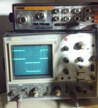
One channel of the Uber amp running on a + - 20v bench supply into 10R load -
Use heatsinks like in Kevin's picture above, I used these 532-529802B25G for the power supply mount the two pass transistors to the case or find a sink, examples are in pictures on this site, As for current for phones, with my phones (Sensitivity : 96 dB/mW) 50R ortho's I measure 2vrms when they are Loud.. 2v / 50R = .04A so allowing for peaks I might need 300ma?
-
kgdynalobal5 is MPSW06/56 THAT340 those are through hole dated 6/5/2015 9:49 AM you can use the SeeedStudio gerber veiwer on the order page
-
and now for something completely different part 3
congo5 replied to kevin gilmore's topic in Do It Yourself
Question regarding the Uber amp.. to make Stereo Balanced Amp you would need 2 input boards, 4 driver and output boards. one GRLV @ 30v for the input spliters and a 30v-0-30v 50va transformer 4) GRLV for the driver/output boards and 4) 40v-0-40v 600va transformers Is this right? -
yea I don't know, the Carbon is my first time with this servo.. +20v would slam the opamp to its rail so instead of pin 6 adjusted for 0v it would be full negative output . the 4n25 can swing 20v more negative than positive? to bias the pzta06? I do not understand............... but whats a few volts dc against a 580v bias..... we will have to wait for the big boys to answer....
-
it looks to me like the opto servo needs the op27 installed as that is where it gets its sense power. which is why to adjust to +20v and the opamp will invert that. I did not get it going yet, but its so stable that every time I check it I decide to hook up the servo later....
-
It seems that there were dual transistor boards with the extra hole .... But that one is MPSW only. the base is in the middle not on a end... EBC vrs ECB I have MPSW if you need a few
-
with 30v rails I measured 2.27v across the 50R .054ma 2.34v across the 562R .004ma so standing current is very low, just add what current you want going to your phones.
-
small size, very low parts count, very low heat output, very large sound.... looking forward to hearing what you think of it! Its different than the CFP2, I like both a lot..
-
I'm waiting on the postman to deliver some Rexolite 2200 2oz copper .125 thick boards, today. Not sure if I should use this one anyway its 1oz copper. The tail resistor would be the 120R connected to the pot wiper, right?
-
Its running, using KGST PS @ + / - 350v all trim pots responsive. Bias set at 80% .8V across 50R for now Output with 100x probe = input at 1x Mouser slow this week so using MJF15030 (backwards) for the KSC2690A's Balance adjusts to 0V Offset adjusts -132v to -146v so need to track that down... may change when using + / - 400v and 2690A led's lit, no smoke, stable voltages
-
Listening now,
-
https://mightytext.net/zPRzoM I have no privileges here to store Images and Google drive doesn't seem to work. so trying that link... Also on other site... under my profile are pictures, also not much to see as they are not pretty, but they do work. I use an homemade CNC to route boards. I completely agree, Its a Great amp. Isn't it about output impedance / the dampening ratio? as well as wattage..... My Firstwatt F5 headphone amp drives smaller speakers just fine.
-
I measure 102.68mm from board edge to top of sicfet ceramic pad. that's with the leads bent at 90, so with a sharper bend....should fit
