insanity
-
Posts
317 -
Joined
-
Last visited


insanity's Achievements
Limited Edition Bronze Participant (4/6)
47
Reputation
-
Yes I used the Kemets 550v 560uf since 680uf were not in stock. I think the original caps were difficult to desolder because i soldered all 4 connections and the leads were touching the walls of the holes.
-
Just wanted to report that the amp is up and running again. Luckily nothing but the blown cap was damaged. Thank you for your support and help.
-
I finally got all four caps out... This was such a big pain without a real desoldering station at hand. I had to cut all caps open to get them out without destroying at PCBs. When open all the remaining 3 had built up pressure in them. I guess it would have been a matter of time until the next one would have given up. I would therefore encourage anyone who has these caps in use to either replace them now, or keep a really close eye on them. Now gotta order the replacement ones.
-
Do you think this type would be fine aswell? https://www.mouser.ch/ProductDetail/KEMET/ALA7DA561EF550?qs=IS%2B4QmGtzzosEBZF0Z4Lbg%3D%3D It is in stock at mouser, whereas the other have a very long lead time. My case is 3U because the old caps were quite high aswell. But if I use some with a bit less capacity, they will be small anyway. If I remember correctly 680uf was overkill anyway.
-
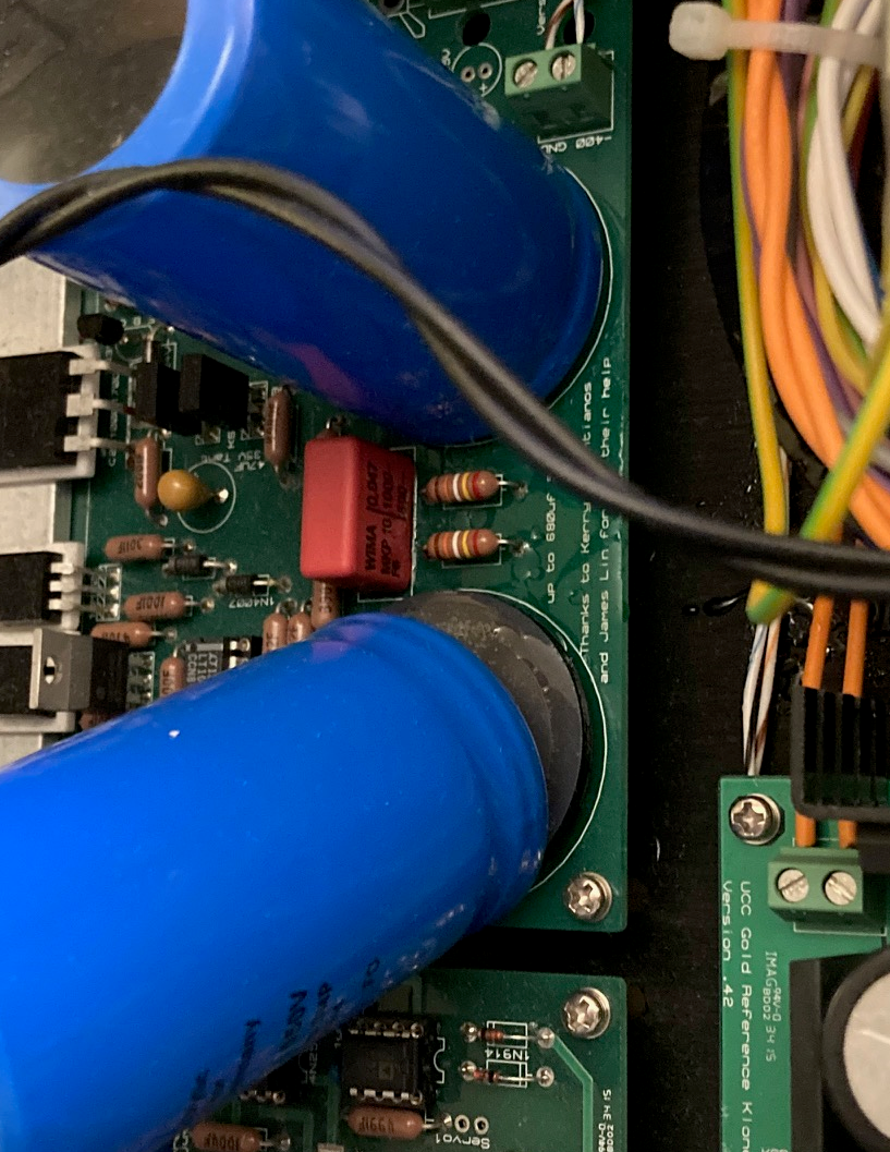
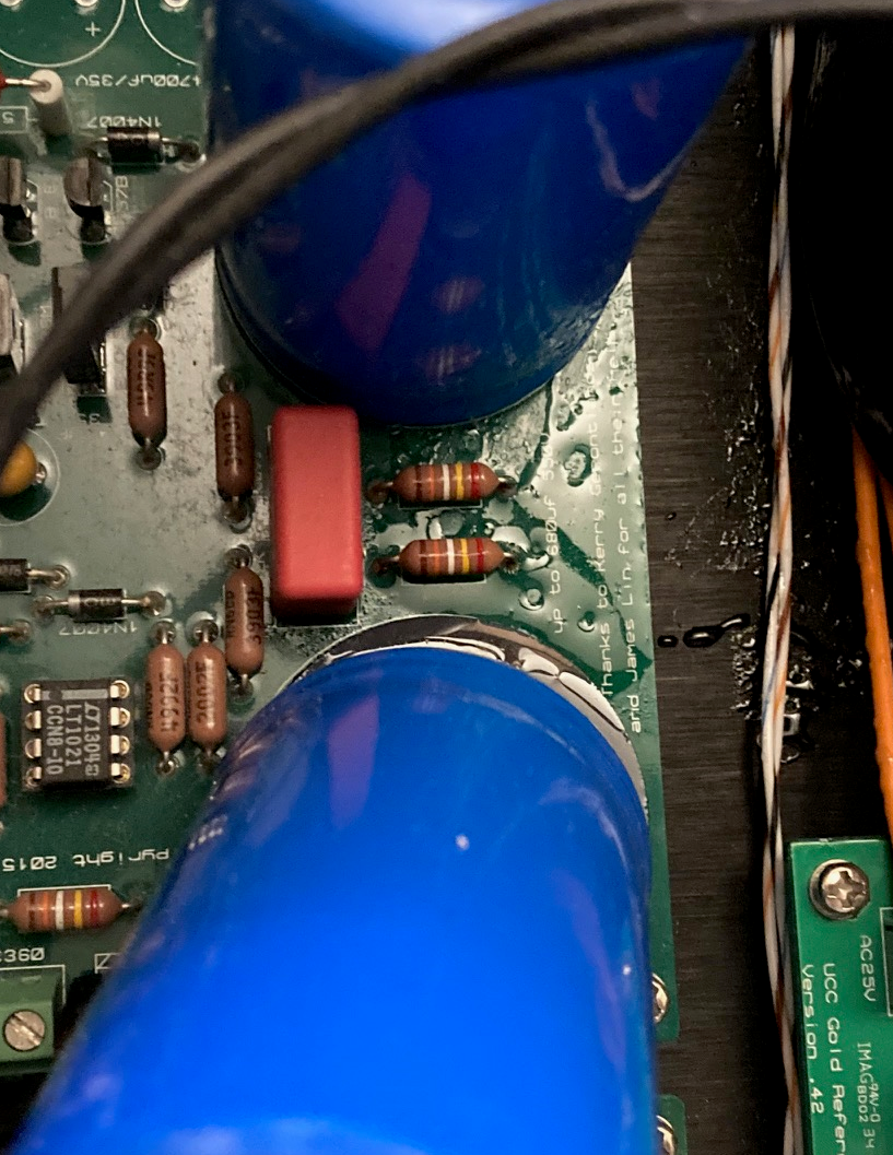
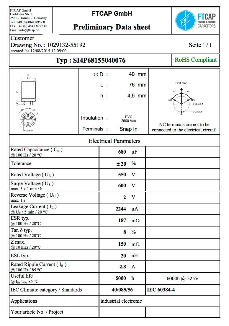
I just had one of the main capacitors blow in my Carbon which is a few years old and has been lightly used. I think its the input cap of the -400v board. The Caps are from the Groupbuy a few years ago (2015 OMG). F&T Germany 550V 680uf. Toroid is 2x 117v (234V AC In) and for the HV 2x330V out. Resistors on the boards for 400v configuration. Any idea what could have caused this?? Usually caps only blow from overvoltage?? The music was still coming through flawlessly after the bang, but I turned it off right away and checked the internals. I hope the other components are ok. Maybe it would be worse if it was the output cap. I am not 100% sure if the other 3 Caps may be slightly bulged or if they came that way from the factory. I will replace all 4 for sure. Does anyone have a partnumber from mouser ready? if I remember correctly a bit less capacitance would also work, right? What is reasonable? Edit: I just read some of the previous post with a similar problem. Maybe these caps are really trash... Edit 2: Just found the datasheet from the group buy I would probably order 4 of these (only 560uf, but should be enough) and hope everything still works after replacing... https://www.mouser.ch/ProductDetail/KEMET/ALA7DA561EF550?qs=IS%2B4QmGtzzosEBZF0Z4Lbg%3D%3D

-
Wow what a beauty! Very nicely done, internally as well as the chassis. Congrats!
-
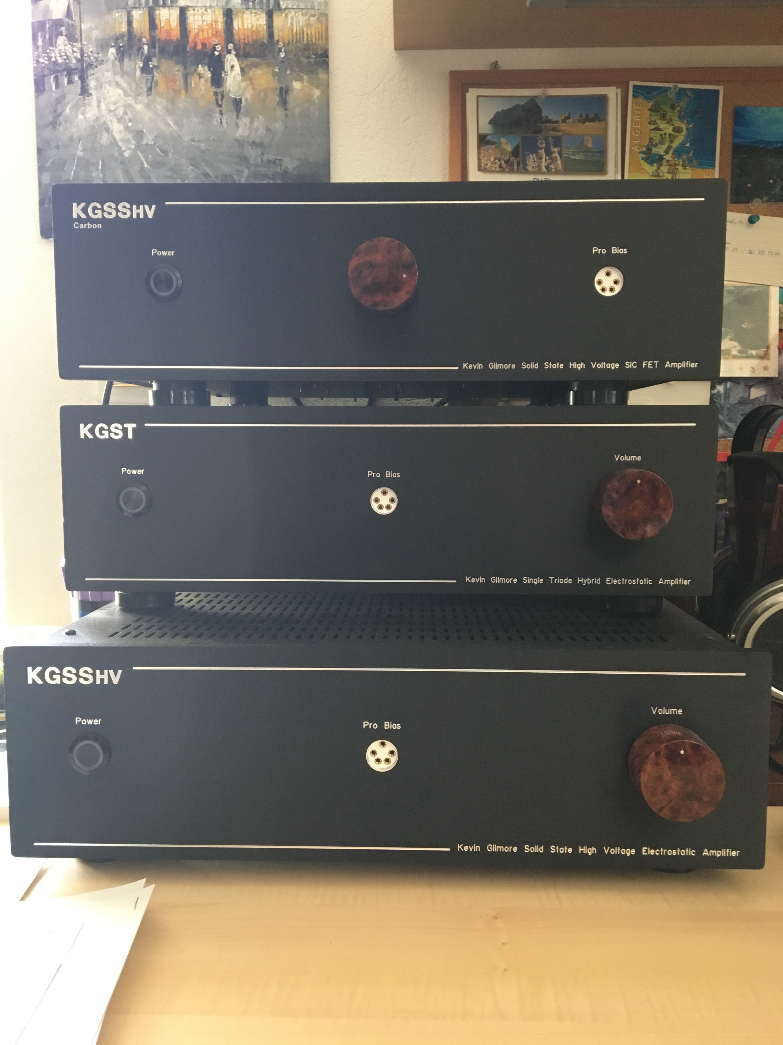
Thanks guys. @livewire I made the knobs myself. Quite some time ago I sold a few pieces here. They are made from a piece of amboyna burl, mother of pearl inlay, PUR boats lacquer. As usual I would not simply call one better than the other. For the SR007mk3 I clearly prefer the carbon, for the 009 definitely the kgst. The conventional kgsshv is a little behind I believe, but also more suitable to the 007 than the 009. From a perspective of build complexity, build beauty and aesthetics the carbon rules them all. The kgst is a rather simple build but compared to that is superb. The carbon with separate GRLV, offboard sinks is a different beast.
-
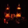
Finally the holy triple with the frontplate of the carbon
-
Well done. Happy for you that everything worked out in the end.
-
The cascode current source can be set with an LV source. Connect positive voltage to B+ terminal of the amp board. Connect negative voltage to the end of the 100ohm resistor adjacent to the DN2540 away from the heatsink. Measure voltage between the testpoints. Adjust until measurement is 1V for 20mA. (Calculation is 50ohms / 0.02A = 1V).
-
Not quite true for me
-
Thanks that is a very interesting fact to know. Do you have a dust free clean room to do your work or how do you prevent dust from entering the drivers?
-
Just out of curiosity. I know you build your own headphones, but what do you do with stax headphones with an imbalance?
-
Wonderful build. What are the red pads under the caps?
-
I have mine repaired and back up and running. Again I am impressed of its sound compared to the conventional kgsshv.