

sorenb
-
Posts
769 -
Joined
-
Last visited
Content Type
Profiles
Forums
Events
Posts posted by sorenb
-
-
12 hours ago, Michelag said:
And another one's singing.
... (apart the offset that needs a screwdriver sometimes... What's the tolerance for balance and offset? Trying to keep em spot on on zero, but slowly drifts away...)
From the picture it looks like you didn't engage the servo?
-
7 hours ago, simmconn said:
It’s not hard to do a 1:1 clone of the PCB.
Maybe harder than you anticipate
Recently I was sent a not working Blue Hawaii BJT.
Turns out the PSU PCB is a clone of Kevins layout ... just flipped upside down, with components firmly mounted on top of the traces ...a year down the road, it went boom, with lifted traces and some literally burned totally.
@kevin gilmore has been kind and provided a modified version of his layout to match the mounting studs in the chassis. -
3 hours ago, Shawn said:
if anyone has good suggestions on how to choose a suitable load resistor for testing
I'd use 300b or 2A3 tubes as load
be aware that NOS tubes may have different results from new production tubes-
 1
1
-
-
On 2/8/2025 at 8:46 AM, Michelag said:
Hello Friends, new member here.
First I'd like to thank those who made my admission possible (Todd, Nate, Kevin).
So, I entered this fantastic world by purchasing my first stax, a L303, at a bargain price, now I need to build an amp 😁
Well, I'm quite experienced (seasoned) in diy audio gear, both SS and tubes, tht and smd, so now I'm slowly gathering ideas, schematics, Gerbers for last working developments of the carbon, please, hints, suggestions, everything is welcome.
A newbie wouldn't be a newbie without a request on his first post 😁, so, if somebody has some spare PCB for this project, and wants to send them (I'll pay postage of course), I'll be grateful. I'm based in central Europe .
So, thank you, and keep going on!
If still relevant, you can shoot me a PM; I have plenty of amp+psu boards+utility pcbs
-
On 6/11/2024 at 2:56 PM, meeskees said:
After adjusting the offset and balance, everything worked properly again
What makes you do that over and over again? do both phases require adjustment?
it might be a clue to look at the CCS's, and whether those are properly connected to the heatsinks ...
You might look at the amount of current being supplied by each CCS with and without hum
-
1 minute ago, JoaMat said:
Emission Labs 20B and 300B, is that the 4 pins socket or the octal socket with center tap filament?
20B octals
300b UX4I got inspired from your Octal/UX4 pattern ;o)
-
4 hours ago, mwl168 said:
So EL34 for the CCS tubes and EMS 20B for the output tubes?
Yep, EL34 for the CCS tubes and (EMS 20B or 300b) for the output tubes
Here's the 20B version before power switch/volume knob etc. Quote
QuoteAny other modifications needed other than accounting for the 20B filament supplies?
Kevin already posted what is necessary. Using 20Bs is pretty straight forward, 300b is another story and requires a bit of tail resistor tweaking.
QuoteFrom picture, it looks like Ecc99s or similar replacing the ksa1156s?
Not using either, but you probably figured that out looking at the above pic 🐵
-
 3
3
-
-
Have been tinkering a bit with the XL'ish.
Build one based on EMS 20Bs and another based on EMS 300b (picture)
A major improvement to the Megatron for sure.
Really enjoyable to listen to, toe tapping.
Whether 20B or 300b I found those pretty similar sounding in this configuration.-
11
-
-
22 hours ago, demonkuro said:
When I measure the negative voltage of the battery, DC offset to ground suddenly becomes -150, I go to check R42, and I find that the R42 in the existing battery becomes 5.8V, some become 6V, and some become other values
maybe start by checkin PSU rails at the AMP boards entry points, and check that all diodes are properly lit
-
24 minutes ago, audiostar said:
Anyone by chance has 4x DN2540N8-G for me?
Mouser showing mid of September for these.
PM me your address, I have plenty
-
1
-
-
Sounds like it's not only the +500V having a problem ...
Have you measured the drop across the "current setting" resistors for the various 10m90's?
Summing up those per rail, might shed some light on the matter ... -
The PSU's I have at hand consumes ~25W unloaded
Exploding 10m90's indicate massive current draw ... have you checked for any carbonization in the vicinity of those?
-
@jokerman777
Based on your post's I'd recommend disassembling both angle brackets, making sure all holes are properly deburred, and all the tappings are clean, also clean all semi's. Make sure the screws can go into the tapped holes using only finger force - if not re-tap the hole.
Re-assemble, using regular compound (the white stuff).
As for the buzz, you stated to have observed a flash in the region of the negative rails, and showed a burn'ed screw from the positive rail, showing that something was cookin here as well, and might have cause excessive current draw from the transformer causing it to buzz-
1
-
-
@jokerman777
The thermal compound looks kind of grey'ish ... do you use some exotic compound?
The screw needs to be able to slide into the 7721 without any force, otherwise it is too big.Maybe you found the cause of the HV transformer buzzing with "no load" ...
-
59 minutes ago, jokerman777 said:
Oh I got parts referencing a BOM where it says stth1512D that is obsolete and I used STTH15S12D instead, I suppose not going to make a difference?
STTH512FP is ready available and fully insulated.
If you look through the KGSShv thread, some had troubles with un-insulated rectifier tabs shorting.
-
@jokerman777looks like you did not use stth512's ?
-
18 minutes ago, simmconn said:
Good to know that the R ch works okay now.
As I understand, the channel has been working all along, just thrown off by the bal servo.
Wonder what the benefit of troubleshooting with the LF353 installed are? -
1 hour ago, audiostar said:
... I think @sorenb did a special power version of it.
Look at the Uberamp output stage.
-
1
-
-
.... are D19/D20 the correct value and both oriented correctly (not flipped)?
There are some good advice to be found in the posts from @simmconn, make sure you have read those.
-
1 hour ago, demonkuro said:
R+ always drifts between -0.5V and +0.5V. All EL34 are bright and hot, and I shuffle their order every time I test, but the result is the same.
Did you test Q24 (J79 in R+ ) ?
-
2 hours ago, demonkuro said:
It seems that only R+ is always working fine?
To me it seems R+ is not working correctly as it seems to be stucked at ~0V
...does it swing toward B+ at power off? have you tried pull the LF353? does the EL34 heater glow? maybe swap the EL34's in that channel?
-
5 hours ago, demonkuro said:
... The output R- to GND was -91V, R+ to GND was 0.05V, L+/L- to GND was -28.6V, ...
Provided the readings are right, I'd look at the right channel LF353 and re-check all the diodes in the right channel servo are properly oriented
if everything seems right, pull the right channel LF353 and see what readings you get. -
Kevin, wish you a UM66T08
-
1
-
-
11 minutes ago, Pars said:
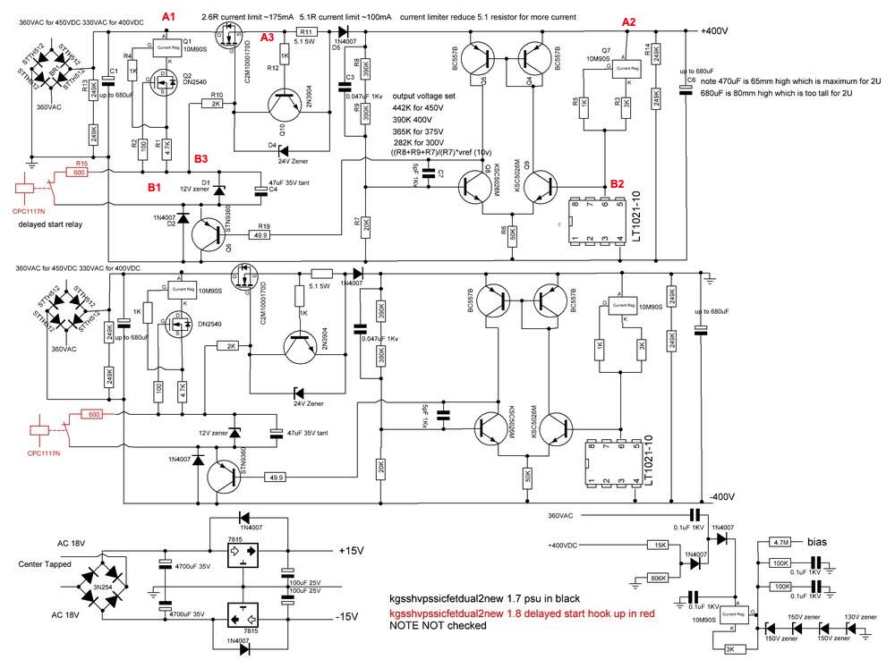
OK, finally getting around to testing the GRHVs I'm building for the Carbon. Using Soren's post on pre-testing, I had some variances.
I marked up the schematic from James above.
- For the first test, using ~17Vdc thru an ammeter, I'm getting 0.5mA (not 2mA) (points A1-B1)
- For the second test, I'm getting ~1.3-1.4mA (points A2-B2), which matches Soren's figures.
- For the third test, I'm getting 10.5-10.9mA (points A3-B3). This may be referring to a Megatron HV900 PSU in Soren's notes below, and I'm not sure I'm looking at the correct points anyhow.
I have a 100K resistor paralleling the two 390Ks. Bringing the positive supply up on a variac until it regulates, it seems to be regulating at 55Vdc, which is about what I calculated. Boards are 1.8 version, single fat sw variants. The voltage appeared to be stable; raising the variac a bit didn't change the output.
Just checking because the first CCS test was considerably lower than what Soren saw. I did unsolder one end of the 100K resistor and rechecked, but no change.
Any thoughts, or just go for full voltage?
"you should get ~2mA" probably a typo, ~1mA is what I usually get, depending on the DN2540 ...0.5mA might be just fine


KGSSHV Carbon Build Thread
in Do It Yourself
Posted
if you engage the servo, you'll see the output will hover around zero pretty quickly