hhobeika
-
Posts
23 -
Joined
-
Last visited
-
Days Won
1
Content Type
Profiles
Forums
Events
Everything posted by hhobeika
-
In my KGSSHV build, I used something similar to your grounding B scheme, and it's very quiet with no noise or hum whatsoever. I did not however use a series resistance and capacitance between the earth and the ground. They are directly connected. The XLR input connectors have a separate earth connection that I connected to the central earth connection.
-
Thank you.
-
I am having the same question as well as the PCBs I have for my next build are made as per the "kgsshvcarbon6ground2" file. From what I could see, comparing the 2 gerber files, the main change from kgsshvcarbonv6ground to kgsshvcarbonv6ground2 consists of moving the low level feedback signal trace for the servo from passing next to the output and high voltage supply Phoenix connector to passing much further away across the top of the PCB. Any feedback on this will be much appreciated.
-
Good catch. Haven't noticed that!
-
I don't think the temperature coefficient will matter in this part of the circuit but I guess both resistors would work just fine considering their voltage rating.
-
I used Vishay VR37000004704FR500 Metal Film 1/2W 4.7M 1% in my KGSSHV. Mouser P/N: 594-VR37000004704FR5
-
For rev 0.4 which is the one I built, it was either to cross the 50k resistors or the 1N914 diodes to correct the reversed feedback, not both. That also resulted in the output polarity O+ and O- being reversed. I am not sure if it was corrected in rev 0.5 but it should be easy enough to check by comparing the PCB traces between rev 0.4 and rev 0.5 if you have both.
-
Those are Nylon Caterpillar Grommet Strips repurposed as wire spacers. I cut them to the number of slots needed. Each is held in place using a tie wrap and a wire tie mount. You can find them at Mouser by searching under "grommet strip". I had some lying around so I can't give a specific part number but they come in various sizes. I only used them on the output wires to keep them spaced in order to minimize the capacitance. More photos of my build at the Dropbox link below: https://www.dropbox.com/sh/4ox0xh7s1aiw5cb/AACdu5DpeRyeFuINloC8HkRFa?dl=0 Hope this helps.
-
Excellently done and very methodical. It was a pleasure to follow your building steps. Congratulations!
-
Very nicely and cleanly done! Looking forward to seeing more progress.
-
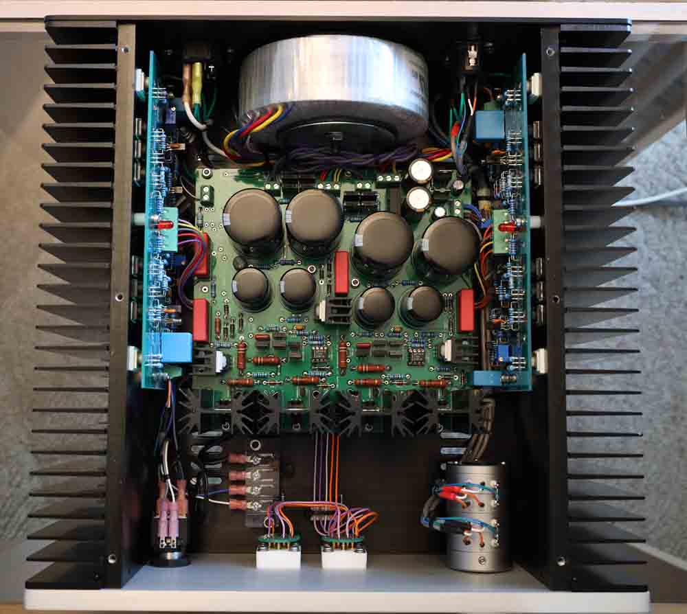
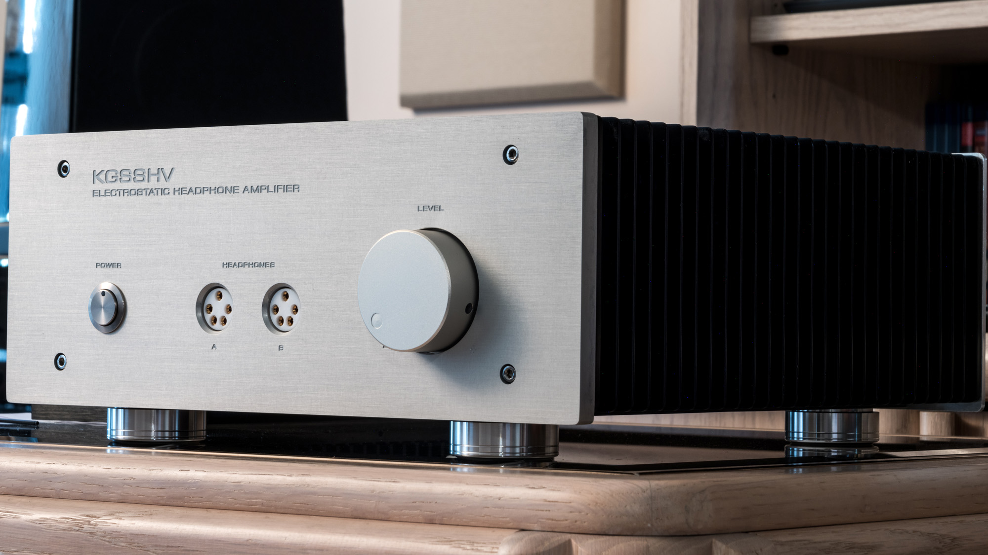
Since photography is a hobby of mine as well, I decided to take some internal and external pictures of my recently completed KGSSHV. Hope you enjoy them. Please click or copy/paste the Dropbox link below to view those pictures: https://www.dropbox.com/sh/4ox0xh7s1aiw5cb/AACdu5DpeRyeFuINloC8HkRFa?dl=0
-
I second this ebay seller as I initially purchased from him. He has large variety of colors. The hook-up wire I used is multi-stranded PTFE #22 for all but the earth where I used #18. Another source that sells per foot that I also used is Remington Industries either directly through their website or through amazon (www.remingtonindustries.com). There is also Bulk Wire (bulkwire.com) but I haven't purchased from them.
-
Thank you. I had the advantage of being late in the game and building on the collective experience in this thread.
-
Here is a picture of the inside. There is a limit on the file size I can upload so I had to dramatically shrink it and compress it to be able to post it.

-
After 5 years from the time I acquired the PCBs and parts, I finally took advantage of the free time created by the pandemic and completed my KGSSHV. This is the offboard version with +/-500V supply. I know many have since moved on to the Carbon but I am very happy with the results and plan on building myself a Carbon in the near future. Hopefully it won't take me that long this time. Thanks to Kevin for the great design, Spritzer for his support and providing some of the parts and this thread from which I learned a lot. The case is from Aliexpress but I got a new front panel made at the local machine shop.
-
Thank you Rodeodave and mwl168 for the info, I am located in Canada and just checked Antek. It's good to have options. In my case, going this route though will require a separate transformer for the low voltage from what I could see on their website. This combined with shipping will get close to the price of a custom designed single transformer from SumR. I will drop the encapsulation option to reduce the size and will check with SumR if dialing back the current on the 15VAC will result in further reduction in size.
-
Turned out the transformer is big because I requested encapsulation. SumR uses few encapsulation container sizes. The transformer diameter with same specs goes down in diameter from 135 mm for the encapsulated version to 115 mm for the non-encapsulated version. The height goes down from 73 mm to 54 mm. This size is more reasonable. The transformer is still shielded but not encapsulated. I am wondering if encapsulating the transformer is of any usefulness.
-
Hello everyone, I am in the process of gathering parts for my KGSSHV Carbon. I am planning on the 400V version set at 20mA and not using the Golden Reference LV boards, just the 2 PSU boards with built-in bias on one and low voltage on the other. Could someone advise on the minimum transformer spec suitable for this build? Looking through this entire thread I have seen a wide range of specs for the transformer. I requested the following specs from SumR: Primary: 2 x 115VAC (to allow for 230VAC when connected in series or 115VAC when in parallel) Secondary: 2 x 335VAC @ 250mA 15-0-15VAC @ 500 mA Shielded and encapsulated The resulting proposed design has 135mm in diameter and 73mm in height which I find huge and was wondering if I should reduce some of the specs to result in a smaller transformer. I don't want to unnecessarily over design the transformer not for cost but for size and weight. Any advice is appreciated.
-
I had removed my pads to check. Everything was properly in place including the springs. I had hard time sliding the pads back in place but eventually succeeded. Not looking forward to replacing the pads later but luckily they look and feel like new.
-
I believe that if I break the seal, then apply pressure to the ear cup, the noise doesn't happen but I will try it again tonight to confirm.
-
Thanks everybody. That is reassuring. According to the seller my SR-007 Mk1 has no repair history. Spritzer, what do you mean by massive stupidity with replacement parts? Parts installed incorrectly, wrong parts?
-
My first post here. A question to the Stax experts. I recently purchased a used but in pristine condition Stax SR-007 Mk1. It sounds and looks great. Whenever it is biased though, the slightest pressure on the ear cup will generate this scratchy noise. By slightest pressure, I mean sometimes even moving my head, the cable weight exerting the pressure might trigger the noise. The manual warns of this and I have heard of it online, but I just wanted to know if it is normally that sensitive. Do I have to worry that I have deteriorated transducers? Thanks for your input.