valve5425
-
Posts
40 -
Joined
-
Last visited


valve5425's Achievements
Advanced Member (3/6)
29
Reputation
-
Great find. Reminds me of a mellower Stevie Nicks, in a good way!
-
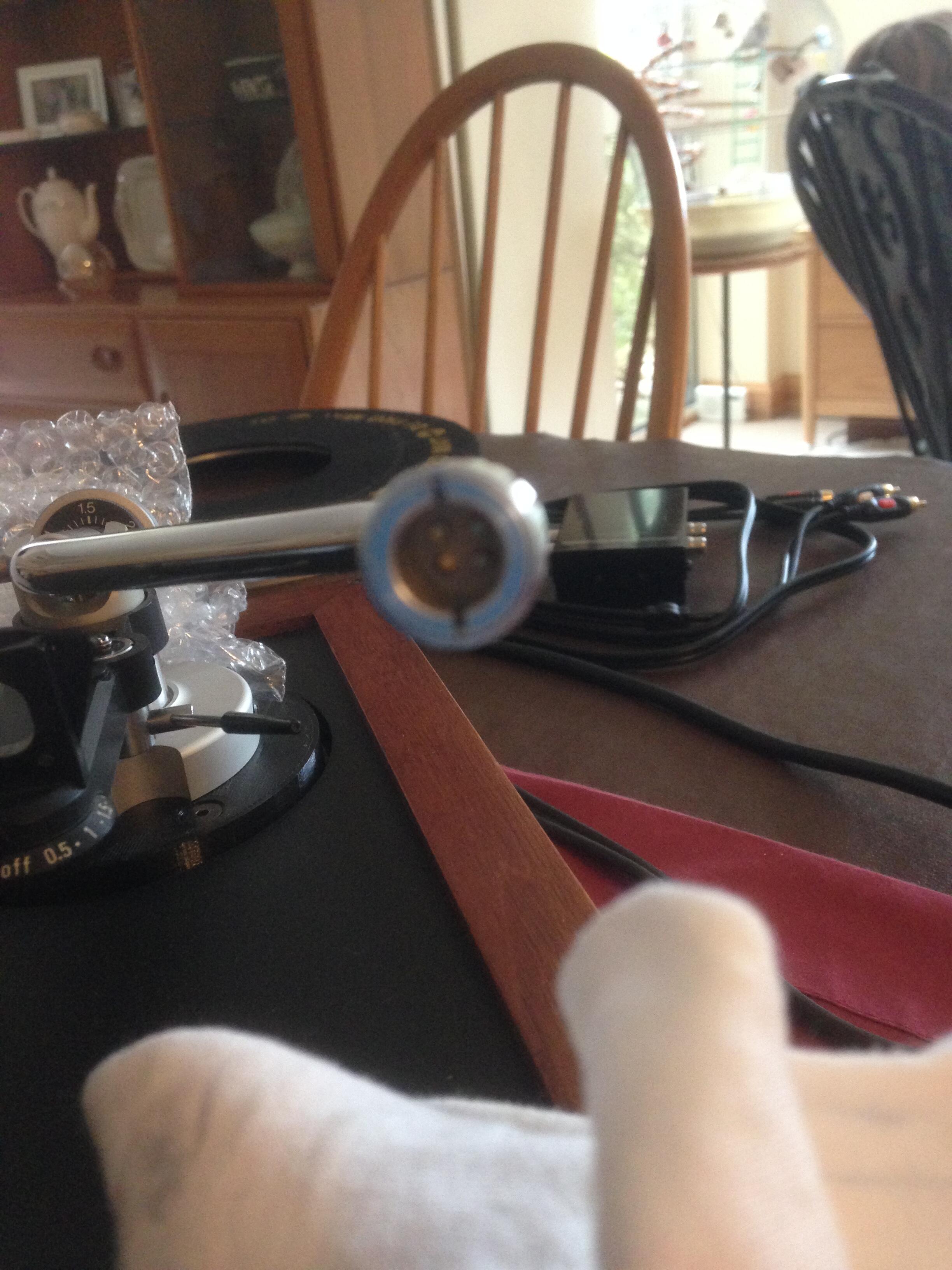
Just fixed my recently sold Linn Basik tonearm on an Ariston RD80 deck. Buyer rang me to give me the great news that he had loads of white noise and couldn't get anything from the right channel! Ooops!! Picked it up off him and found that when the cartridge had been fitted, the sprung pins in the tonearm/headshell connector were gummed up and weren't springing back. Lots of solvent spray and a bit of persuasion from fine needle nose pliers. Woohoo! Problem solved. Happy buyer and even happier me. Can probably afford a better camera now and post better pics!

-
Nice one. Thanks for that. 👍 Seems a bit arse about face. Yellow for silver and white for copper??? Maybe I'm too logical.
-
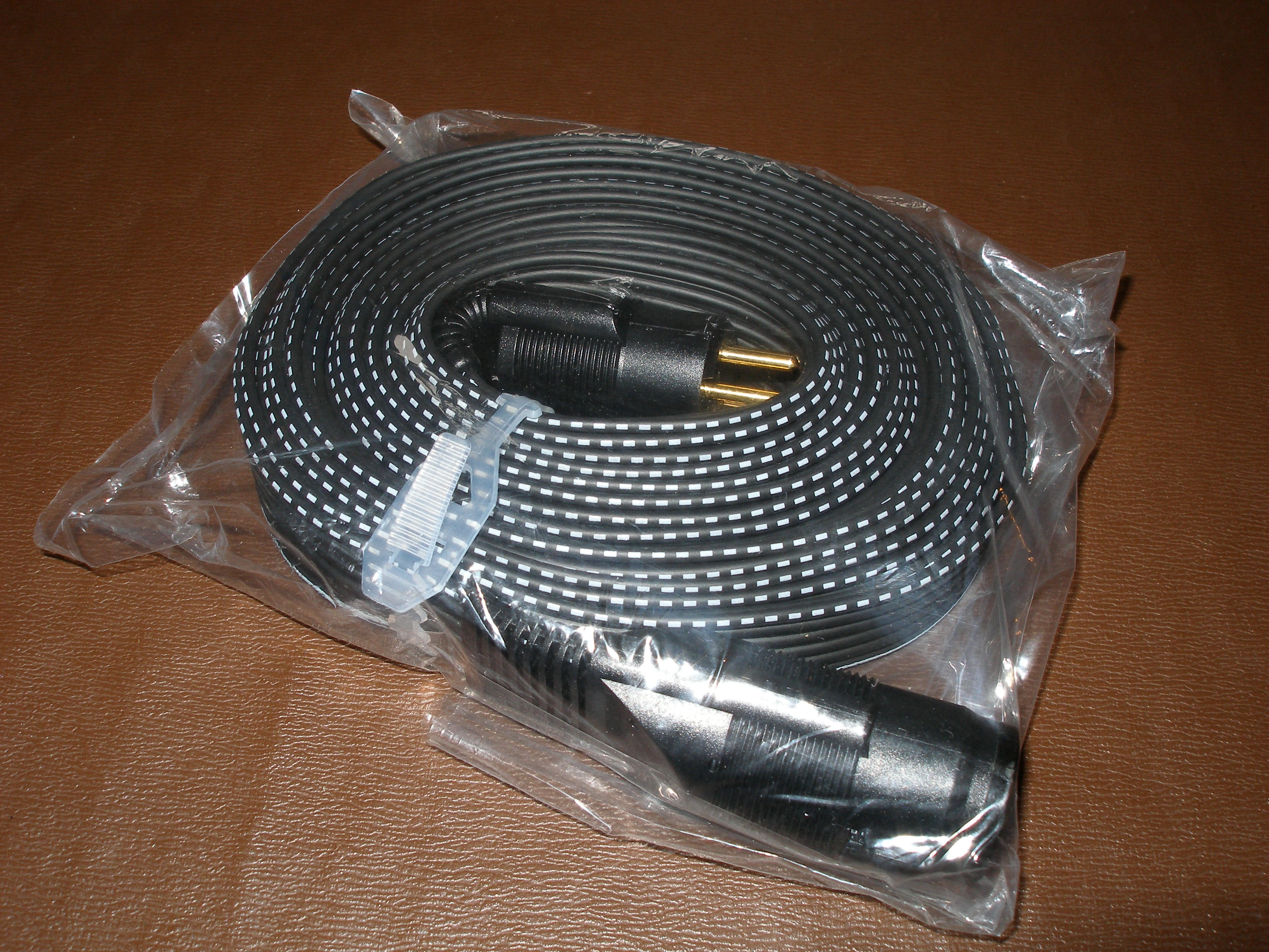
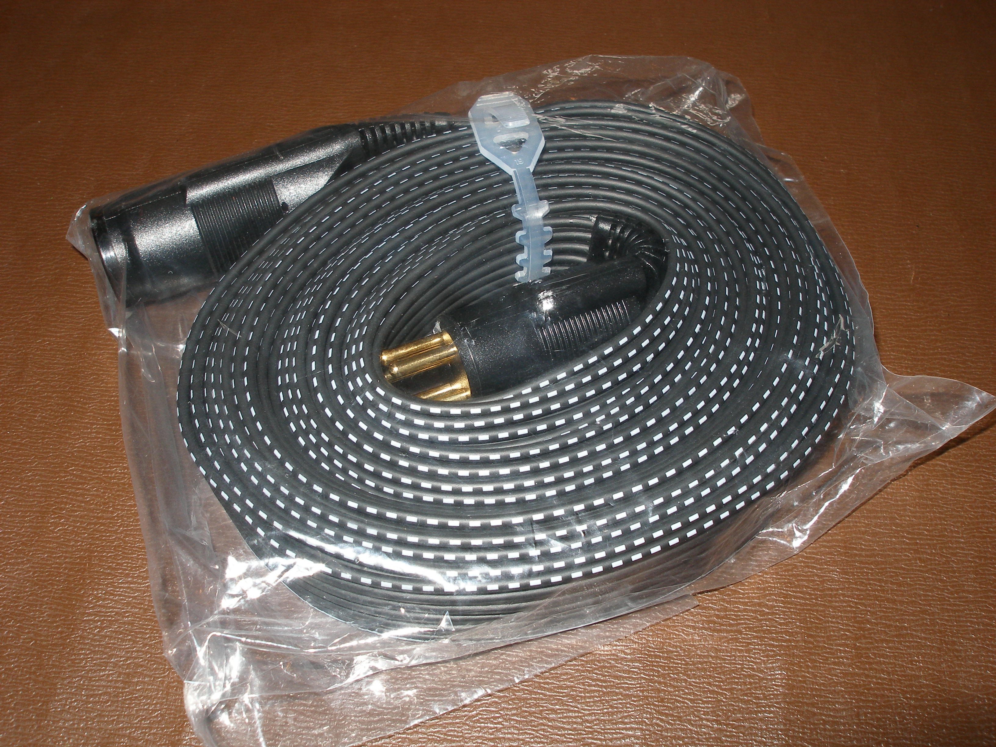
Can anyone enlighten me on the visual difference between the SRE-750 and SRE-950S extension cables? I'm struggling to find anything other than stock photos, which aren't helping. I'm guessing the ones I've acquired are 750's. Thanks.
-
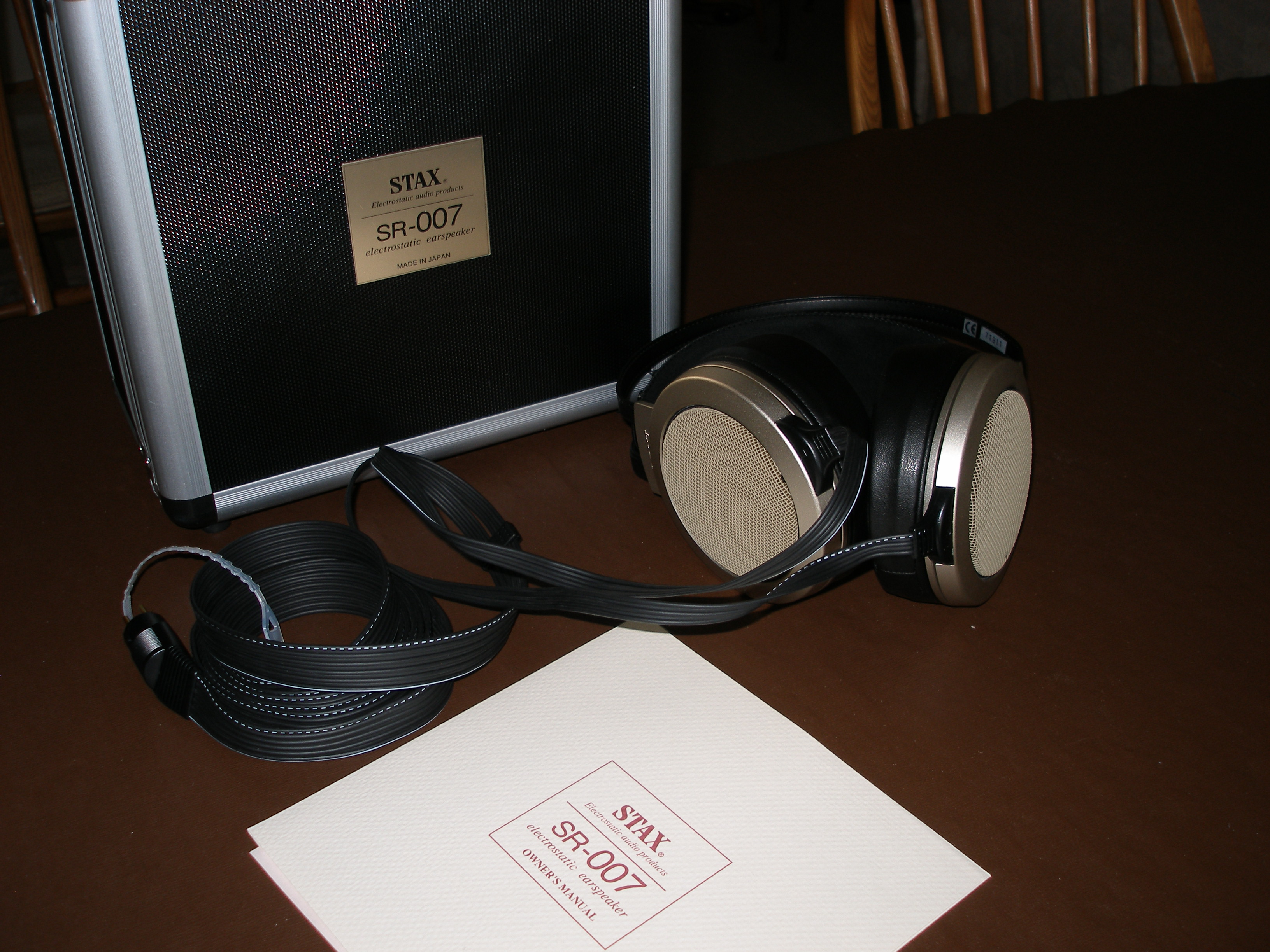
A pair of mint SR-007 Mk 1's arrived yesterday, so my KGST should be happier now! Bit of a step up from the SR-313's I've been using.
-
Page 4 of the Addendum I posted July 15.
-
Just had a hunt through my files and I've got Gerbers, but don't have the PSU schematic, so can't help with that. Ooops! Didn't realise there were non-pro versions. Did say I was old!
-
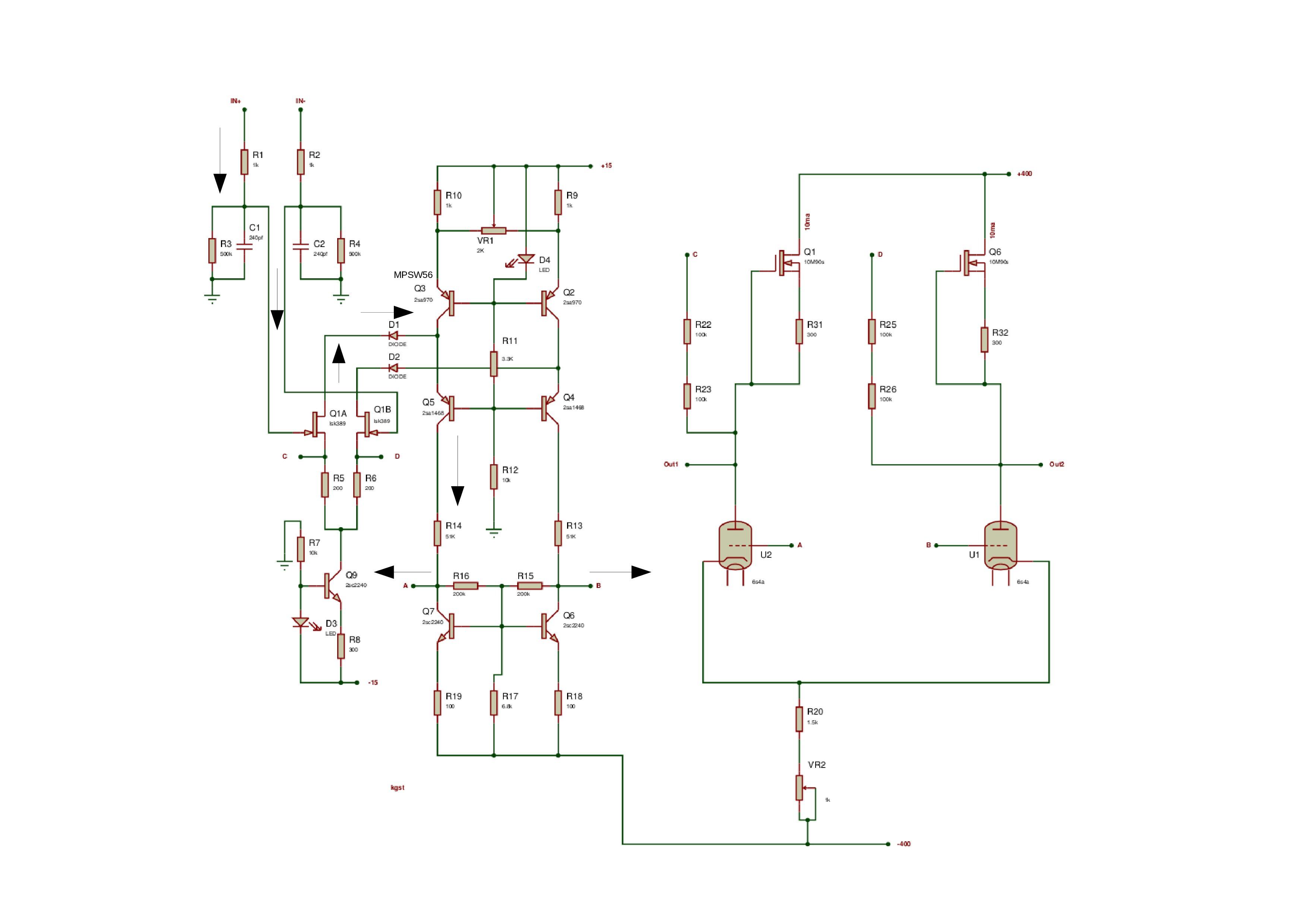
Listen guys. The info's in here, you've just got to hunt, start building and then shout out when disaster strikes! Built mine 4 years ago, and I'm old, so I've forgotten a lot since then, but to get you started here's a list of questions and answers, and other info I cobbled together after trawling through the posts. Might be useful. I've also attached a schematic I have in my files as well. If you know where you can get a quad of 6s4a's from, don't tell anyone else, just let me know!! You'd have to check through the posts for any significant changes over the past 4 years. FWIW, I got my custom TX at a good price from Toroidy in Poland. It's worked a treat, but there are plenty of other places out there. Good luck! @matthew-levi Thought everyone was using the KGST with Pro output? KGST info addendum.pdf
-
Very stylish, neat build! Like your graphics.
-
Looks like you worked it out yourself! I guess you could populate the board normally and fasten it upside down to the top panel of your chassis. Then use short wires from the bottom of the board to tube sockets bolted to the underside of the top panel. However that raises the problem of adequate heat sinking as they don't tend to work too well upside down! Maybe you could use something like a http://uk.farnell.com/amec-thermasol/mhp-1220a-100a/heat-pipe-ultra-flat-1tx100l-mm/dp/2290468 to replace the big sinks, (you'd need to size that appropriately) fastened between regs/mosfets and the top panel. But then it's getting complicated and you'd probably be better just getting modified boards made, or use connectors like I did!
-
@charlo89. I've used MPSA's (06 and 56) in mine, no problem.
-
Here are its innards! http://knob.planet.ee/amps/stax/stax.htm
-
I've slept on this and now recall that when I initially looked at designing the case, there was also the problem of heat sinking if I flipped the boards. I did consider pushing the heat sinks through holes in the top cover but decided it would be messy. One solution of course would be to bolt the TO-220's directly to the top and fasten a fancy heat sink on top. (But then I guess if you wanted to use a 3mm copper lid, it would have sufficient mass to negate heat sinks!) Fastening directly also gives you the problem of having to re-seat the TO-220's every time you take the boards out for tweaking/repair. Just a thought I had after I'd built this, was to place the 24V zeners on the bottom of the PSU board. (Wish I'd thought of it before I built!) As they are designed to blow if disaster strikes, then they would be easier to replace. If anyone's doing a re-design then it should be possible to position them on the outer edge of the board and not tucked between the heat sink and caps. However, with the current board, future builders may want to consider them underneath.
-
Thanks Blueman2! No reason really, just figured this would give best access to the boards without taking all the case apart. Also, I didn't like the idea of all those electrons upside down! Good luck with your build. Cheers. Hmmm. I could send you some photos of it completely naked if you want?
-
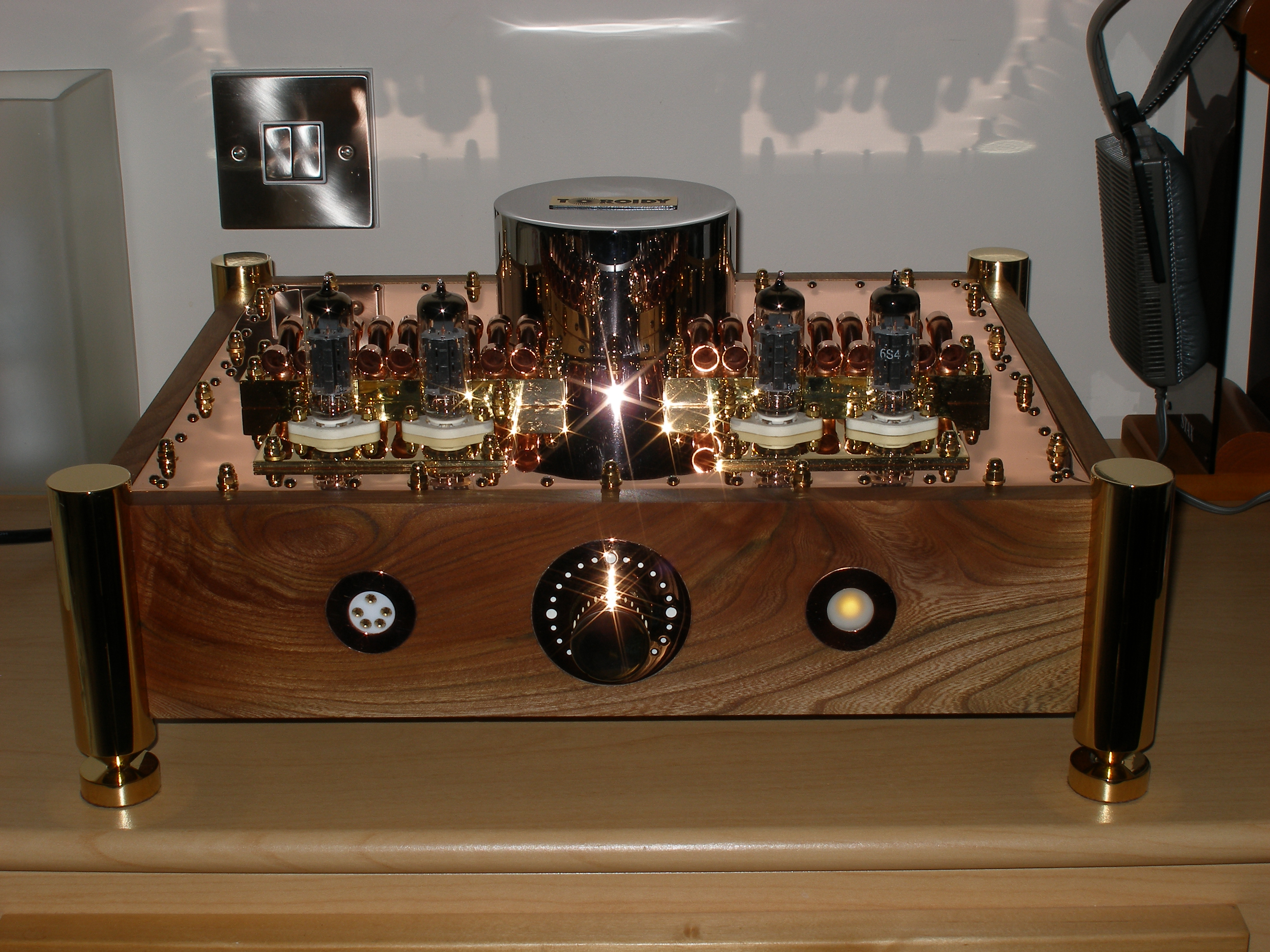
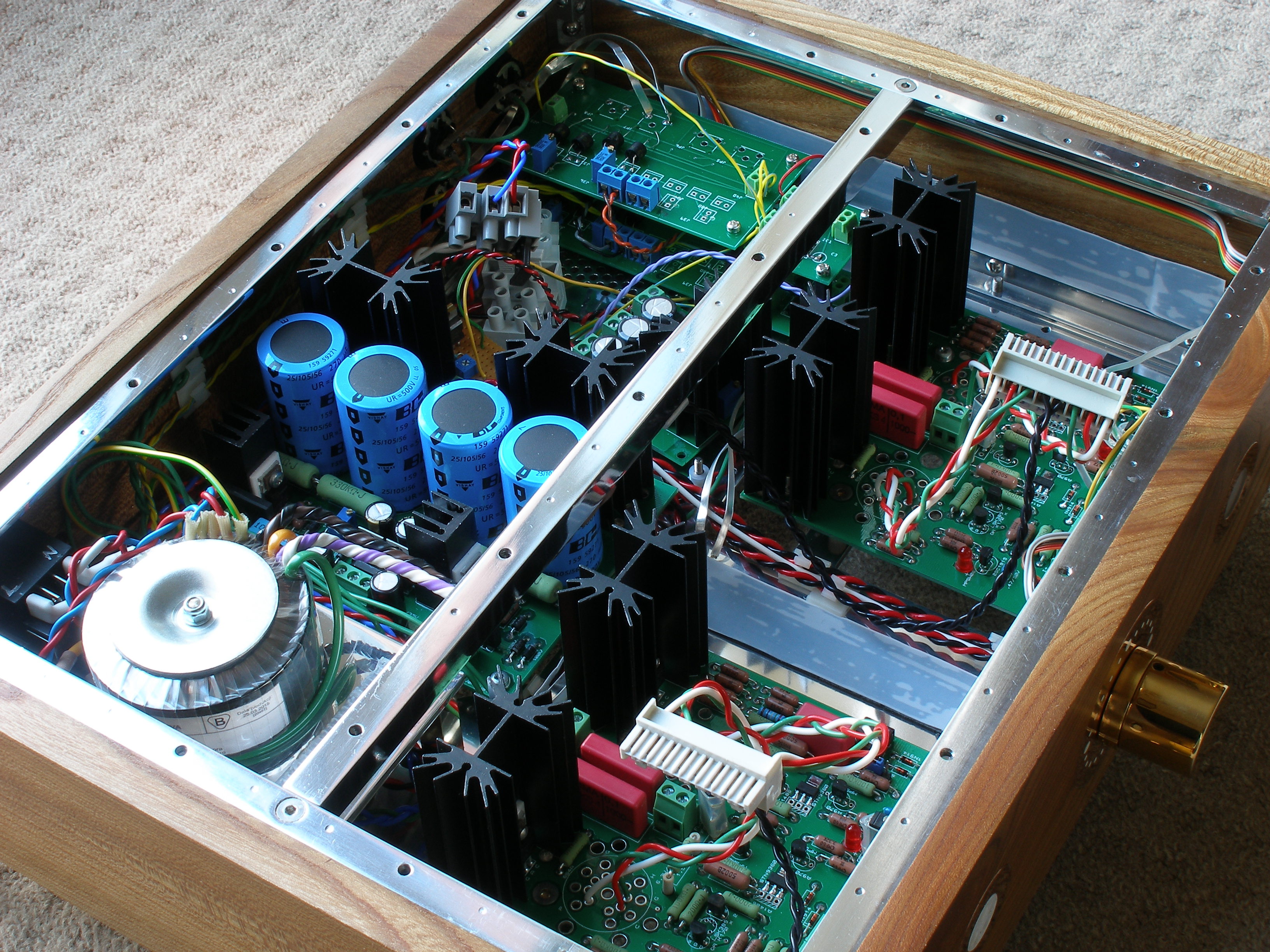
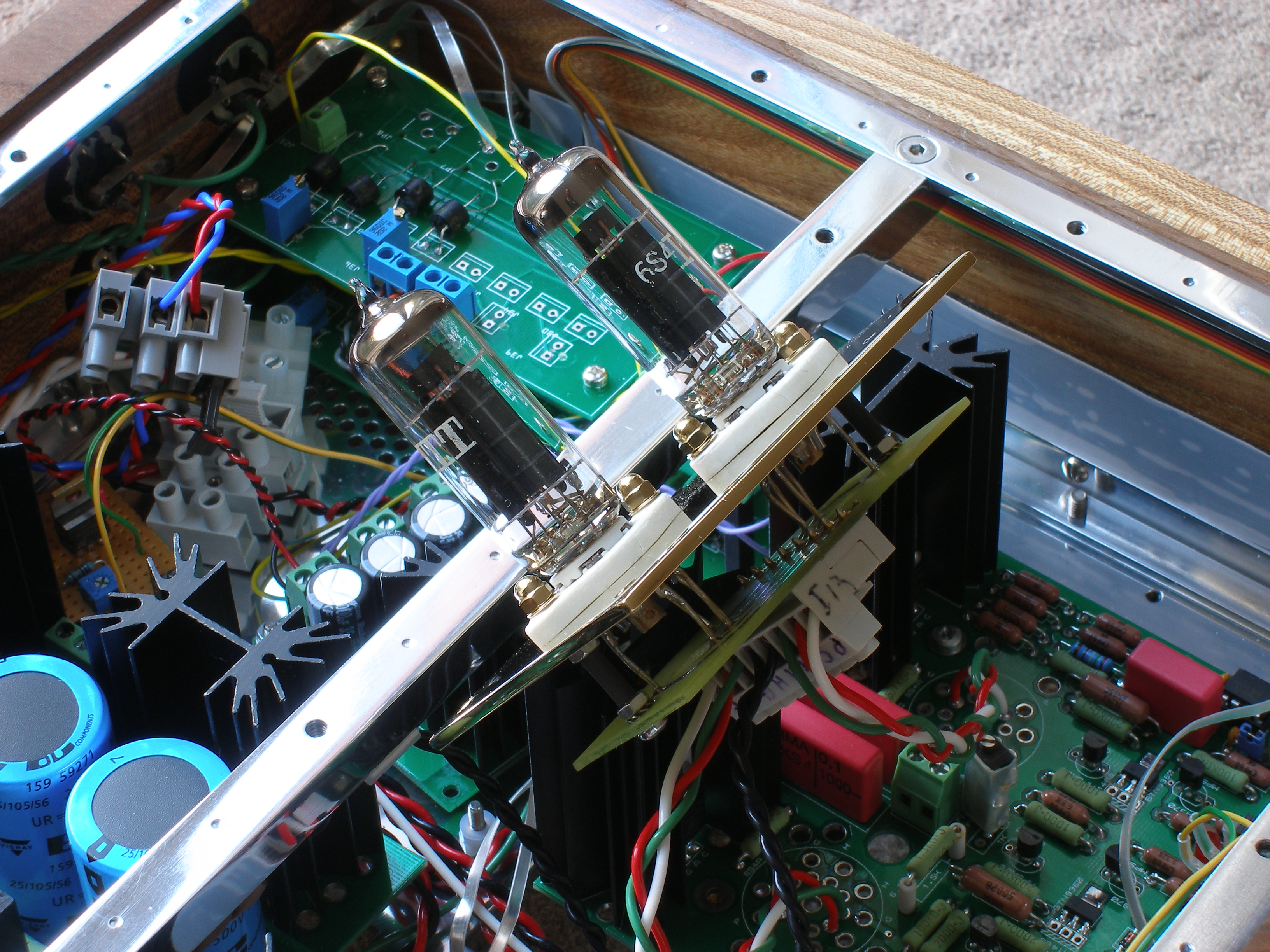
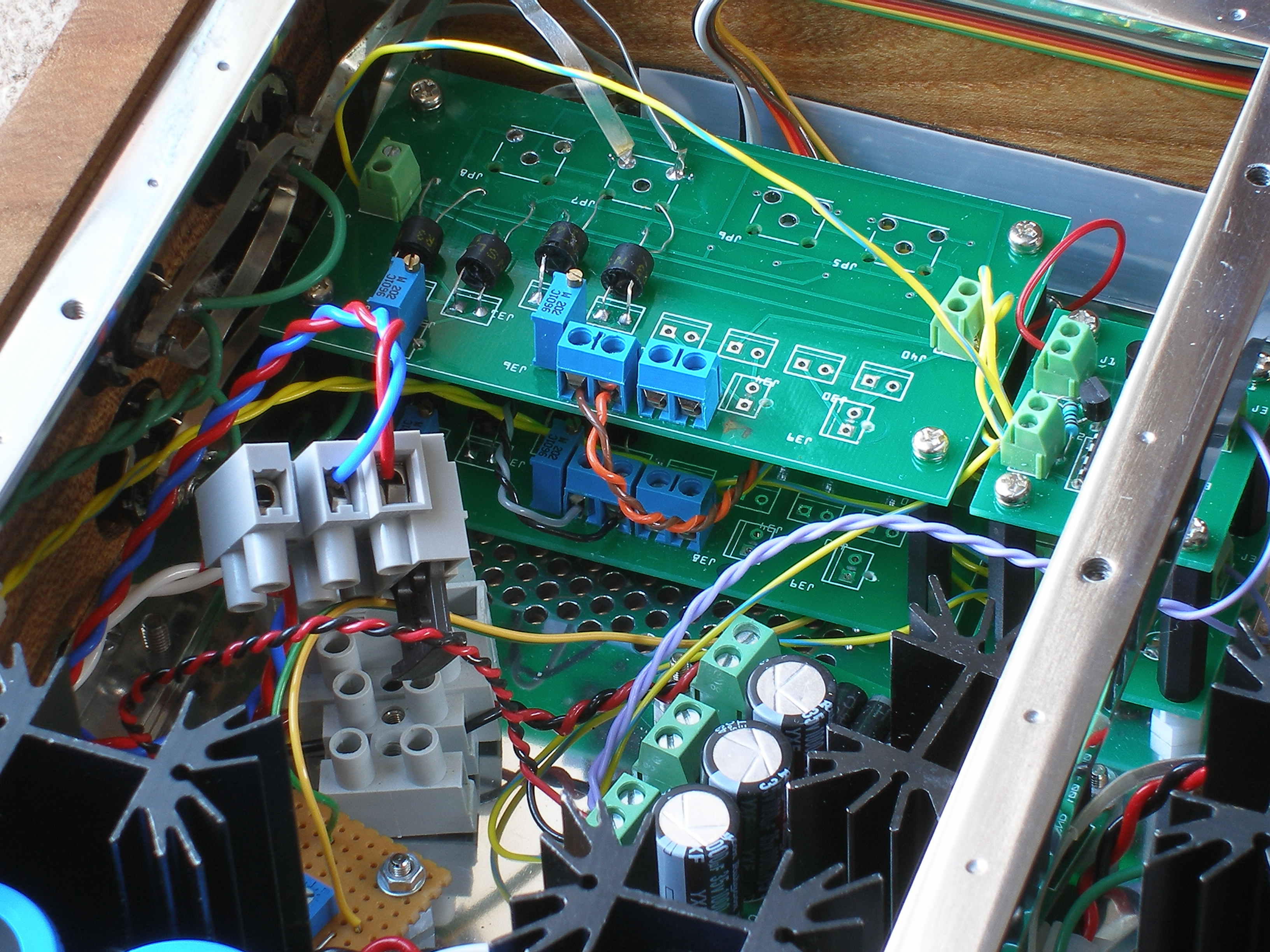
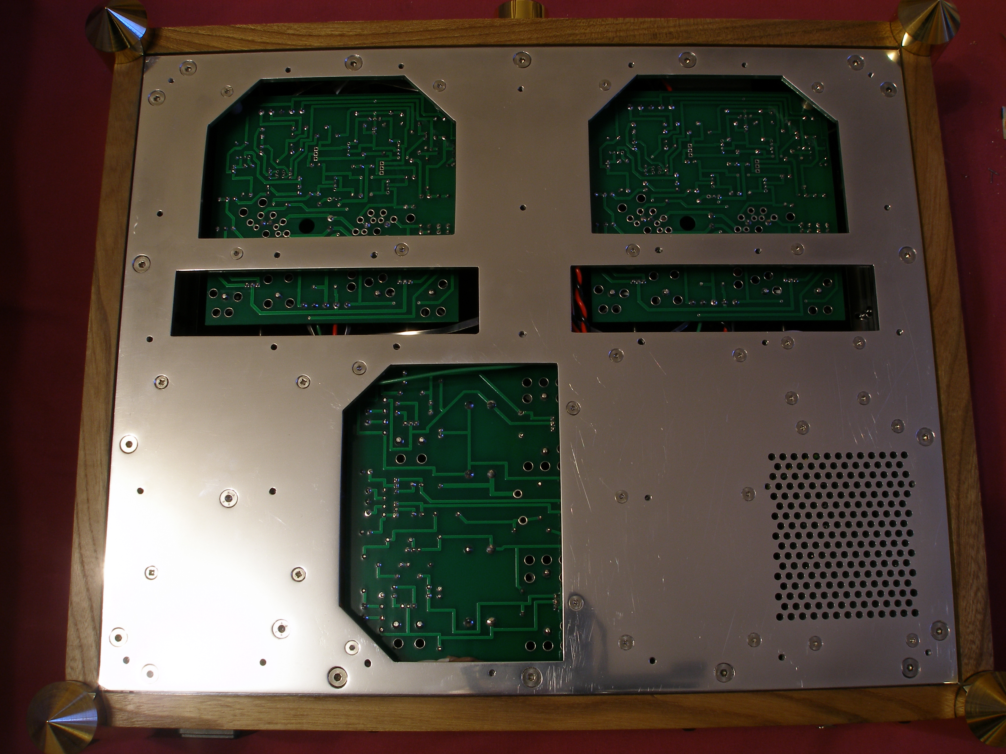
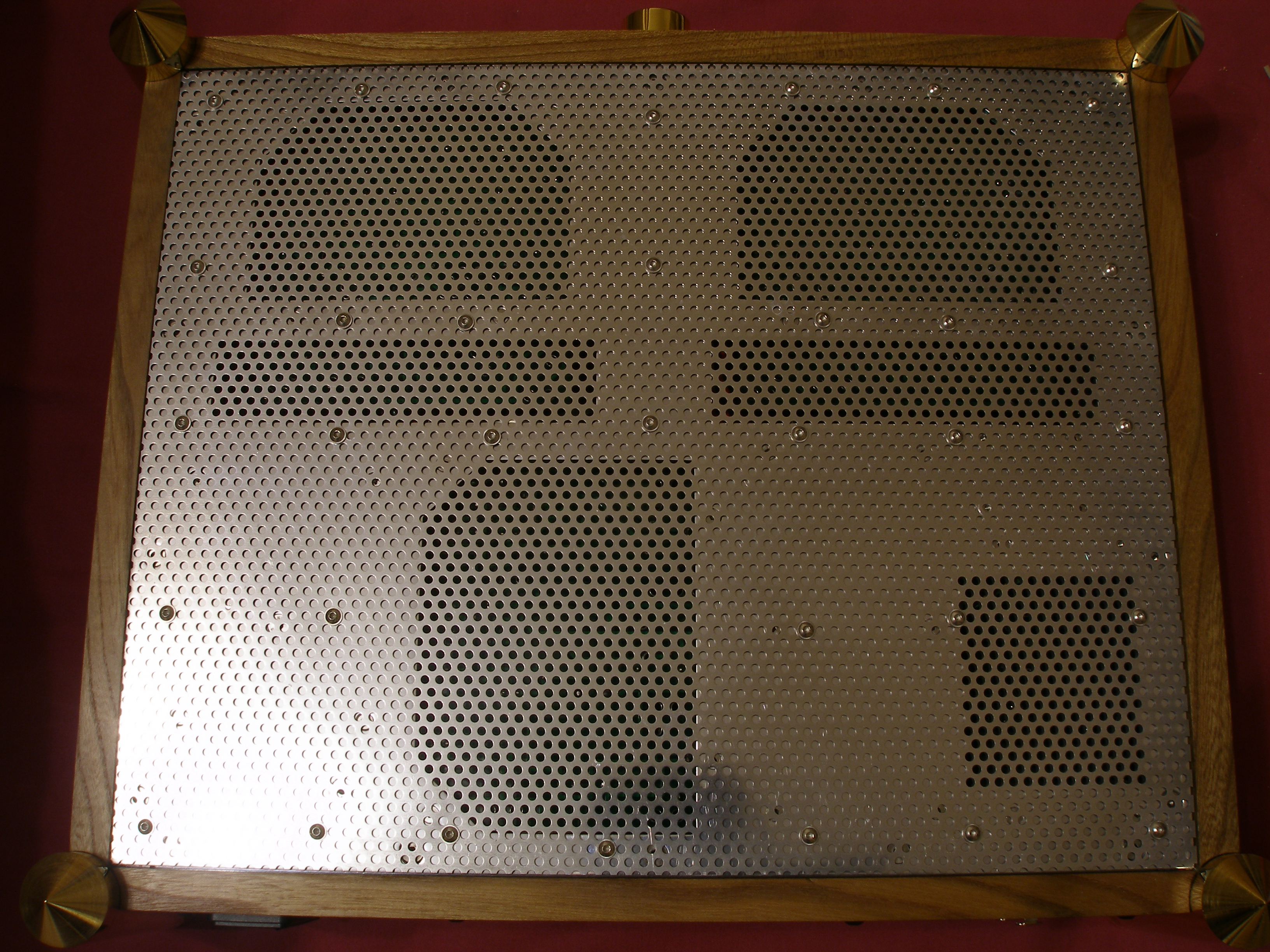
Finished!! Running at 375 volts, (I like to be different) and 10ma. 1K3 cathode resistors with the 1k0 trimmers. 42° C at the heat sinks (psu around 32° C) with the top barely getting warm, so no heat issues. PSU is actually putting out -377.37V and +376.16V when warmed up. There's less offset without the servo, around 200mv, so jumpers are out. I've designed the chassis base to enable access to the boards from below. Also the brass valve platforms are removable, so balance and offset trimmers can be accessed without removing the full top cover. Signal wiring is 4n silver foil, everything else 600V PTFE. Power lines twisted and heater wires run along the top of the chassis, so no hum. All grounds to star earth located near to the filtered mains in. The volume control is an LDR kit (4 boards in the rear right hand corner) which I thought I'd try. I know the potential issues with these but it doesn't seem to be having any negative effects. I fancy playing around a bit more with LDR's to see if there's any mileage in them, but if I get bored with them I've got room for a conventional attenuator, so I'll see how it goes. I know I said it was finished, well, almost. Just need to re-etch my relay/delay and 12V supply board for the LDR's which will slot in where the terminal blocks and small board sit next to the main psu board. Slight printing error, that I hadn't spotted, meant it had shrunk the image horizontally. Dooh!! TBH, it's not really needed, but it gives me something to do. It's been 12 months from the design stage but well worth the effort. Oh, and did I mention that it sounds bloody fantastic? I guess that now I'll need to upgrade my SR-303's. Thank you, Kevin Gilmore, Spritzer and anyone else responsible for the design of this amp. Now, did someone mention a T2?