Helium
Returning Member
-
Joined
-
Last visited
Everything posted by Helium
-
-
Hi Kevin, is KA5 fully-differential amp? I guess it's not, want to make sure. If it's not, then for balanced operation 2 boards are needed, and one board amplifies any 2 signals from L+ L- R+ R-. Is it correct?
-
What is exact board size of balanced Dynahi with onboard heatsinks (aka dynahibal8f)?
-
Can someone please explain what AT1000 data is? Is it related to Amprobe AT1000 tracer?
-
Kevin, is this thread all devoted to goldenreference4.zip? What about goldenreference and goldenreference3? Is goldenreference4 direct replacement for those? And you opted to get rid of TO-3 transistors?
-
It's because e12's virtual ground is referenced to PS ground. Imagine you are using 2 sigma22 and only 1 e12, which is referenced to one sigma22. Even if you built both sigma for the same voltage, due to parts tolerance the DC voltage of both will not be identical. Even 0.1v difference of sigmas output will make e12 false trigger because it will think that DC offset is 0.1v+amp's native DC offset.
-
Try AMB's e12. I'm using it in almost every build of beta22, and will use for dynahi as well. To my opinion, 0.5v is too large and may damage some headphones, while others will survive. Anyway, I wouldn't risk my collection of 1000-1500USD headphones. I want the amp to be as most universal as possible.
-
Kevin, are Golden reference boards finalized? You mentioned that there is oscillation unless some parts are not omitted...
-
Sorry going to order for myself only, no experience to start GB if you meant it. Also, it's going to be rather expensive. The price of PCB house I've used to deal with is around 18-20USD per PCB of Goldenreference for the lot of 4 (180x110mm, double layer, FR-4, 1.5mm, 70um).
-
Checked rectangular knockout punches of many makers, couldn't find one that cuts hole for IEC at once (punch size and IEC size must match). So will stick to RS 545-345 which is 28.2 x 22.5mm for my favourite Qualtek 764-00/002. Will have to cut 4 overlapping holes. OEM is Manuform MA9730140. BTW, they have MA9740040 which is 31.4 x 28.3 with radius corners, but that is 2 times more expensive.
-
Yes, please call Goldreference stable and final, and I will order PCBs. Interested in on board version.
-
With big output transistors? But why would you need it if Susy dynahi exists? What's the major difference? I guess none. AFAIK, it has always been like this: dynalo = w/o big output TO-220 transistors, dynahi = with big output TO-220 transistors.
-
Minimum quantity from Mouser is 1 pcs (2SA1930). Same from BDent (2SC5171). Ah yes, 2SA1930 is in stock in Digikey. Minimum quantity is 1 pcs. too.
-
Try Toshiba 2SC5171/2SA1930. They are available at Bdet (2SC5171/2SA1930) and Mouser (2SA1930). Grab them!
-
Aaa want! Seems that I will add 1 more PS case with goldenreference. It will be 5 case setup: balanced beta22, Susy dynahi, Krell clone, Sigma22 PS, Goldenreference PS. All amps will include full setup of AMB delta1/delta2 with screen and motorized pot. PS cases will include Sigma11 for 5VDC as well, 2 transformers and Crydom/Tyco SSR. I've buit maybe 15 Betas already, this one will be most complicated and for myself.
-
When things are changing so fast, it's hard to follow the story. So, Goldreference is the updated and improved KSA5 PS board, right? This one: http://gilmore.chem.northwestern.edu/boards/ksa5psg.zip And it also must be compatible with KSA5 clone, Susy dynahi. Seems complicated (no no, not a drawback). Curious how is it compared with Sigma22? Maybe worth to try it with Beta. On silkscreen, 2000 Ohm resistors marking near DC output are upside down... What should be changed to push it to +-24V? +-30V?
-
Wow IEC punch. Can you give punch maker/model (greenlee, ruko, qmax...) and corresponding IEC maker/model? I'll look into it.
-
It deforms inside (punch side), not outside (die side).
-
Power is still necessary Harder to match them. Anyway, there are just 4 of them per board. It's OK.
-
Thanks, I see now. Offtopic: any plans to update dynahibal8, dynahibal9, ssdynahibalsmt and the like as well?
-
Like what board? Can you give a link please? I far as I have seen from repository, all KG dynamic amps have only top copper ground plane at best. Which one already enjoys bottom ground plane?
-
So, is it end of the game SS dynamic amp??? What's your opinion?
-
Hmm you switched to SMD? Pity. Any chance to design them simultaneously please - SMD and all TH? I've got plenty of MPSW.
-
IMO square hole punch is useless for me. I've got one, 1inch x 1inch, and never used it. Not to mention they are very expensive. However, round hole punches are used very frequently. I've got the whole set from 10 to 31mm to fit all Neutrik connectors, pots etc. Avoid D-holes and square holes as much as possible. Round holes are much easier to cut. And more accurate. I even chose to install separate Neutrik powercon+switch+fuse holder combo instead of single AC inlet module. Just for the fact that the latter requires square hole.
-
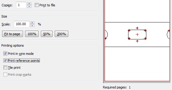
I've experimented a lot on drilling precisely located holes. This is a technique I've developed for myself and it's working for me. Drilled >20 cases already. 1. First make drawing in FPE software to the size of your panel/case. In the drawing use as narrow lines as possible for increased accuracy. 2. Print it with scale set to 100% (A4, A3, A2 or whatever your panel size is). This is very important to ensure that printer/plotter prints precise size according to drawing. Sometimes the printer outcome is different by fraction of mm/inch to what you expect. It will ruin accuracy. Measure the paper drawing with ruler ot caliper. If not perfect, either calibrate the printer or search for another one. It may take time to find a printer/plotter which prints precisely. Also, make sure you use the following settings as on screnshot attached (this is all about FPE software, other software setting may be different). Print in B/W mode, not color so that only one printer cartridge will be engaged for maximum accuracy). 3. Cut the outer shape (=panel shape) of the drawing with Xacto knife guided by metal ruler. 4. Stick it precisely to the panel by using glue (you will remove it later with solvent). Don't apply too thick layer of glue. As thin as possible. Wait for the glue to harden. 5. Now you proceed to drilling itself. Slightly punch reference points to be drilled on paper with carbide scriber. The scriber must protrude the pater and reach the metal to leave mark on it. This is very important to put the scriber exactly in the center of reference point (funny enough, it's harder than you can imagine). That's why I recommend to apply thin layer of glue and use thin paper for printing. Use good lighting and magnifying glass if necessary. I use this carbide scriber: http://www.amazon.com/gp/product/B00004T7S1?psc=1&redirect=true&ref_=od_aui_detailpages00 6. Punch paper (and panel underneath it) with automatic center punch. After you mark the center of the hole with carbide scriber (step #5), it's easy to punch it with center punch, it doesn't wander. I use this center punch: http://www.amazon.com/gp/product/B000HTAH70?psc=1&redirect=true&ref_=oh_aui_detailpage_o02_s00 Try to punch once only. Only if you see that it is offset, make second ot third strike to remedy. 7. Take good screw-driver drill, preferably cordless. Chuck must be good (tricky to find drill with chuck that doesn't stagger on the shaft). 8. Make starting cavity with drill bit for ceramic tile. It has totally different shape from usual drill, but it doesn't wander. I use this one: http://my-shop.ru/shop/products/1885540.html?partner=6414&gclid=CjwKEAjwkcWrBRDg5u6SuPS11C0SJAChLLAHXLrav1hkXKRHwcnHVHuU2tZX_i9WsiFiGHJPUOUJKxoCu9zw_wcB Mine has 4 cutting blades. 2 cutting blades (more common) will do the trick as well, I guess. Just make small cavity with it. Don't try to drill through, of course. Always apply oil at drilling. I use WD40. The cavity made by ceramic drill bit will ensure that the final drill bit will not wander. As you can notice, the whole process is about minimizing wandering of the bit. 8. Now you are prepared to drill the final hole. Don't try to use generic drill bit. Instead, use spotting drill. I use this one made by Europa Tool (if talking about 3mm hole, there are different sizes): http://www.ebay.co.uk/itm/3mm-HSS-Co8-90-DEGREE-NC-SPOTTING-SPOT-DRILL-EUROPA-OSBORN-8214020300-D25-/271833566150?pt=LH_DefaultDomain_3&hash=item3f4a8b0bc6 What's so special about spotting drill? First, it has very short fluted part. It means that it's sturdy and doesn't bend when you press the drill against the material. Believe me, drill bits under size of 5mm with large fluted part do bend when you press it down. Then, it has no side cutters. It means that it cuts material only with its tip. Side cutters tend to bite the material which make the bit wander sideways. Use oil at drilling and VERY low RPM (~1 revolution per second). For that screw-driver drill must be used, not usual drill. Screw-driver drill will maintain torque at low RPM. Spotting drill is not designed to drill trough thick material, but it's good enough to drill through 3-4mm. And yes, when drill panel up to 1.5mm thick, don't use drill bench. Better by hand (just control it that you hold the drill vertically). 9. You are done. Remove the paper and clean the panel. Deburring may be needed (I use Noga tools). This method is about drilling small holes (e.g. for screws, standoffs etc). For large holes (e.g. for Neutrik connectors), knock-out punch must be used (that is another story, and there are also some trick to share).