Blueman2
-
Posts
289 -
Joined
-
Last visited
Content Type
Profiles
Forums
Events
Everything posted by Blueman2
-
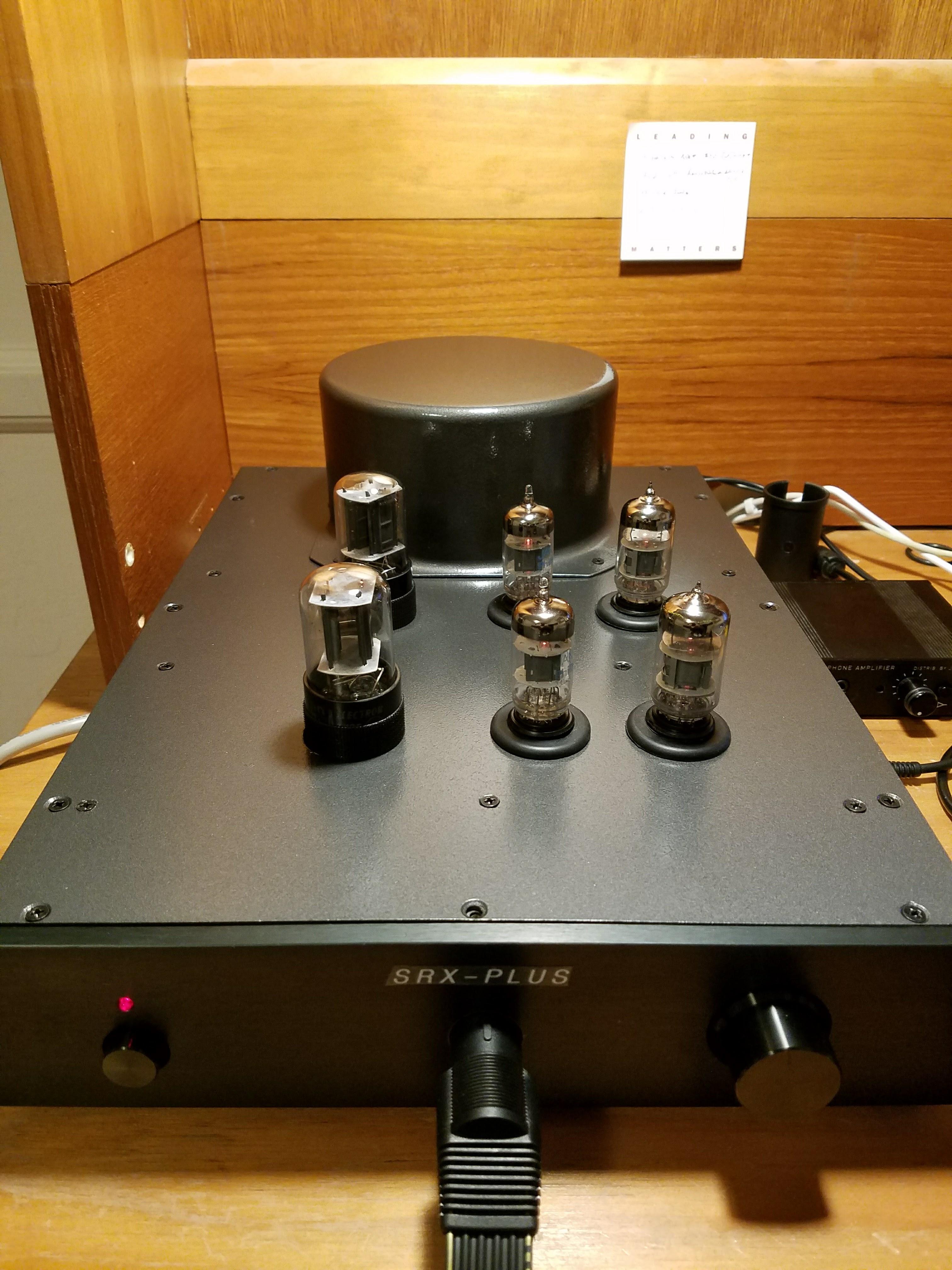
I thought I would provide an update on the sound of my 2 SRX-Plus amps. I used new Penta Labs quad 12at7s that were balanced and matched in both builds. I used some existing NOS 12AT7s I had laying around and could not balance the amp correctly. With new balanced and matched Penta Labs, it was a breeze to get the amp dialed in. Then for one amp, I used new Tung Sol 6SN7GTBs, and in the other, NOS GTA Sylvanias. The Sylvanias sounded better out of the gate. cleaner and crisper sound. Tung Sols seemed a bit muddier. I have been primarily listening to the Tung Sol amp for the past week, and it appears that over time, the amp has become more clear and defined; less muddy. I am not sure I believe everything I read about break in periods for headphones, speakers, tubes, etc. Much of the break in talk is not supported by objective measurements so I am skeptical. However, it sure seems that something has changed in the Tung Sol amp over time. And I don't think it is just my ears because I have been using an HD650 Sennheiser as reference for comparison. Both driven from the same O2 DAC/AMP source, with line out of the O2 DAC going into both the O2 Amp (for HD650s) and the SRX-Plus (for SR-507s). Of course, the SRX/507 combo always won, but at first, the HD650s just seemed cleaner less muddy. There was and is a surprising amount of bass coming from the SRX/507 combo, but the bass seemed too muddy and was somewhat fatiguing. Now, that muddiness in the SRX/507 seems mostly gone. Still not perfect, but better. Not sure if this is a combination of the amp settling in, the Tung Sols breaking in, the Penta Labs breaking in, my final dialing in of the amp outputs (my offset was about 70V or so before I did all the tuning to get it to essentially 0V after warm up), or maybe my ears getting more used to the sound. But the SRX seems to sound a bit better every day. I have about 30 hours of listening time on it so far. I will report back when I cross 100 hours. I did notice that when I put the NOS Sylvania SN7s in my amp instead of the Tung Sols, it does sound noticeably cleaner and clearer. Perfect, really. No trace of muddiness at all. And that is without retuning the amp for these tubes. So perhaps there is something to be said for either the quality of those old tubes, or the fact that new tubes need an extended break in period? Why do I continue to use the Tung Sols, you ask? Well, because my son's ears are much better than mine, so he gets the good Sylvania tubes! For someone coming from Dynamics or even Stax driven by SRD-7, I would rate the sound as SRX-Plus/507 >>> SRD-7/507 >>>>>>>>>> O2Amp/HD650 So I would strongly recommend the SRX-Plus build. Just be aware of the importance of good tubes both in dialing in the amplifier and in quality of sounds. And if using new tubes, given them time to break in.
-
Ah. I thought maybe Stax of Mass Destruction. But yours makes more sense....
-
SMD? Don't know that TLA.
-
After completing the 2 SRX-Plus builds, my mind is already wandering to what is next. I am leaning towards a solid state amp just to have something on the other side of the spectrum from the wonderful SRX-Plus. If anyone has any spare boards they can part with, let me know!!! Otherwise, I will keep my eyes out for the next group buy. I have caught the Stax bug in the best possible way.....
-
Thanks, guys. On my new amp (above post) , I was not too far off in terms of output offset or balance. But on my older SRX-Plus, which is what I have been listening to most, the output offset voltage was over -120V on all outputs. Way off. So I did the same adjustments as I outlined above, and WOW!! The amp had a much better tone. Broader soundstage and more clarity. I wish I had done these adjustments before! I thought they were mostly for tube life, etc. But unless I am mistaken, it does have a very noticeable impact on sound. Enjoying my finely tuned SRX-Plus right now as I type. I just cannot turn this thing off.
-
mwl168 or others, With everyone's help, I was able to get my second SRX-Plus so stable that I went total OCD and decided to balance everything within an inch of its life. I ended up adjusting the 100R output CCS trim pots to get balance between + and - of each channel to be equal, and used the 20R pot to get offset to 0VDC. So after about an hour of warm up, all 4 outputs read less than 1VDC (measuring from GND to each of L+, L-, R+, R- outputs). I then adjusted the 500R pot to get upper plate voltage back to exactly 1/2 of B+. Fine tuned the 5K pot to keep plate voltages equal. So from these measurements, I think I have it dialed in about as good as I can. However, this setup leaves me with about 3.3ma of 'extra' current sink between output current sink and source rather than the target 3.0ma . I assume that is OK, right? Here are my final measurements across the test resistors: Output current loads: R+: 6.83ma R-: 7.00ma L+: 6.50ma L-: 7.01ma Output current sink: Right: 17.18ma Left: 16.78ma Input current sink (340V B+ rail, 300K plate resistors): Right: 1.07ma Left: 1.06ma Does this all look OK given that the outputs are now balanced and offset to 0, and upper plates are equal and 1/2 B+?
-
Damn it, JimL. Must you always be right? First, you intuitively guess a bad DN2540 on the input tail CCS and were right. Then you intuitively guess 12AT7 issue and, again, were right. I put in all of the known good tubes from my prior amp, and the new amp is now acting and adjusting perfectly. Rock solid and steady, even with SE config (cold input tied to ground). And even with the filaments still elevated. I did not think at first to try that because I had already put all those good tubes in the new amp and it did not help. But that was when I still had a bad DN2540. JimL, you absolutely rock the STAX world!! mwl168, jose and mypasswordis, thank you too for your help. I very much appreciate this wonderful community.
-
Will do. The amazing thing about this very simple yet elegant SRX-Plus design is that even with it being way out of spec for plate voltages, the damn thing still sounds INCREDIBLE! It might not last long in this condition but I cannot help but be amazed at the quality of sound compared to the SRD-7 I was used to.
-
They are essentially the opposite, right? Floating means there is no reference DC voltage applied and the filaments will float to whatever makes them happy. Elevated means I have tied them to a known reference DC voltage, such as +60V for the 12AT7s. Is that right?
-
I do have both filaments elevated. 12AT7s are at 60V (voltage divider off B+ rail) , and 6SN7s are at -340V (tied directly to B- rail). I did this to eliminate hum. I do of course have have 2 separate 6.3V windings (I modified my board to use 6.3V for 12AT7s) so they each are elevated to their own levels. But this duplicates what I did on my first amp, and on that amp I found elevating the filaments actually made balancing the amp much easier. But let me try removing the elevation and see what that does. I did check all the DB2540s on the board. All show about 11 ohms across Drain to Source. They should be showing about 17 ohm according to the spec sheet, and indeed the new one I put in (to replace the one that showed open circuit across D to S) does read 16 ohms when installed. All are from the same mouser order. I will put -10V across gate to see if they are working correctly just to be sure. Right now, I am pulling all the tubes from the known good amp and putting them in the new amp in the same positions just to rule out tube issues, as JimL suggested.
-
OK, then I must have another problem. Because I can balance the amp with inputs are open/floating, but as soon as I tie either cold input to ground, I cannot even come close to balancing the 2 plates. same on both left and right channel. But you are right, because I was able to balance the first amp I built just fine with cold tied to ground. I wonder if I have more bad DN2540? I did a quick and dirty test on them, and aside from the one that showed open circuit between Drain and Sink, all the others show the expected 10-17 ohm resistance. Very odd.
-
Oh, and jose also brings up a good point. I am now able to balance the amplifier perfectly and the voltages are now stable (I could not get it stable with the bad DN2540). But as soon as I tie COLD INPUT to GND, I am back to delta between plates being around 90V. I assume this is normal? Because everything seems just fine when COLD INPUT is left floating. I assume settings should be done with nothing attached to inputs or outputs? In any case, JimL, thanks for the lead on the DN2540. Amp is now stable and sounds GRRRRRRRRRREAT. Apologies to Tony the tiger.
-
BINGO!! One of the DN2540s was indeed bad. I had not tested those as well as I had tested the 10m90s because I had it in my mind the 10m90s were the place to start. JimL, you saved me many hours of replacing all the silicon which was going to be my next step. LIFESAVER!!!! Thanks!
-
Thanks for the quick reply, Jim. I did exchange the tubes to ruled that out. I am using 300K plate resistors and they test right. So I will replace the DN2540s. Should I focus on just the 2 per channel on the input tail CCS (the 2 near the 500 ohm POT)? I was not sure if you meant to also replace any of the DN2540s that are associated with the 10m90s. Thanks! mwl168, the plate reference to grounds starts at 360V on power up (which is my B+ rail), and then goes all over the place. Of the 4, one goes steady to 90V (I think this is the only one acting correctly), and the other 3 sort of go all over the place and never seem to settle down, often at 220V or so.
-
jose, yes I have both cold channels tried to ground. No volume control on it right now.
-
I need some advice/help on tuning my latest SRX-Plus amp build. I tried to duplicate what I did on the first amp I built which I was able to adjust per the settings in mwl168's post earlier in this thread. I have the 7ma adjusted on the output current loads and 17ma on the output current sink. I then try to do step 6, which is When I do this, the voltage difference between the two plates swing wildly, eventually settling on a 120V delta between them!! When I power on, it shows about 8V delta for 10 seconds. Then when the tubes kick in, the voltage goes from about 100V to 0 to -120V delta over a period of about 30 to 45 seconds. On my first amp, it will swing briefly, but will always settle down on a value less then 10V delta. Of course, the 1K pots cannot come close to resolving that big of a delta. I replaced all the tubes with known good ones from my other amp and get exactly the same result. I also ran the same test with the other channel, and get exactly the same result!! So if I made an error, I made it perfectly across both sides! Any idea what could be causing this? Interestingly, the amp sounds just fine when listening to it with my 507's. But having such a huge plate voltage delta is a concern to me. One possible cause could be that when doing a low voltage test (1/5 power with a variac) I realized I have reversed the B+/- rails. I corrected that before the full power up. Could that have fried the silicon and be causing this issue?
-
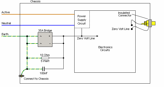
Thanks again, jose. I just wanted to document here the ground loop breaker circuit that I think you were referring to. It seems to have worked well for me.

-
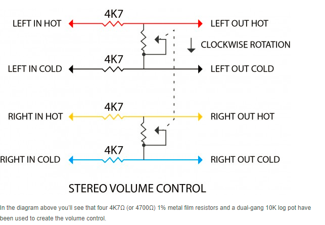
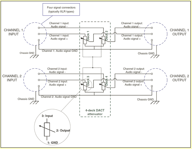
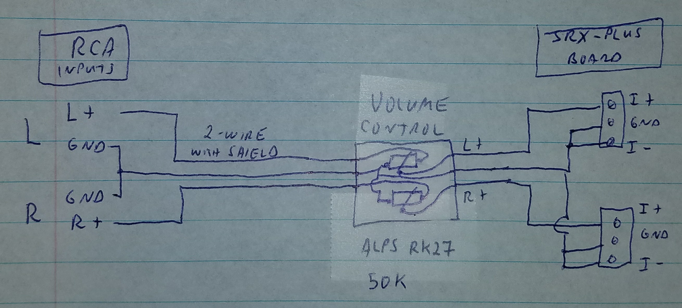
I found this drawing by Rob Squire of AudioTechnology, which shows how to do 2 channel balanced volume with a regular dual gang volume control. This will attenuate the signal by about 6db, but I think this is acceptable for most sources. The issue for me would be using unbalanced input by shorting cold to ground. In that case, since colds are tied together with ground, there will be a linkage between left and right through the 2 10K pot resistors: 20k between left and right when full volume, even less when volume is lowered. As you near lowest volume, left and right will be almost 100% connected!! That leakage probably kills this idea, right? Thoughts? This is the wiring recommended by DACT using quad volume control:
-
So I have decided to build another SRX-Plus amplifier but keep to XLR balanced inputs rather than RCA. But that brings up new issues with volume control. Do I need a quad potentiometer? I am pretty sure I will need to reduce the volume equally on both the + and - signals for each channel, so 4 pots (quad)??
-
Well, my son and I just completed the build for our second SRX-Plus. Went more quickly and more smoothly than the first build using what we had learned already. I am finding that getting good tubes is essential. With the right tubes, it is a breeze to get everything dialed in per the specs. With questionable tubes, is can be impossible. Oddly though, I cannot tell the difference in sounds when the amp is not dailed in per spec with the trim pots. For example, I had a upper input plate to plate voltage difference of 120V using some poor tubes!!! But it still sounded just fine. With a different set of tubes, I was able to dial it down to 0V delta, but again, no real difference in sound. Just perhaps a bit less hum. So by my counting, there are at least 9 SRX-Plus amps that are built and running: JimL congo5 MLA Sorrodje mwl168 luca jose blueman2 (my amp) Juggernaut1101 (my son's amp) I am sure there are others, but I went by who posted pictures or said they completed the build on this forum. I find the SRX-Plus to be the perfect mate for SR-407 (my son's) or SR-507 (mine). I would love to see how it sounds with SR-007 or -009, but don't feel the need for that $$$ upgrade yet given how great my SR-507s sound with the SRX-Plus!
-
Thanks, Pars. I double checked how the wiring is done on the volume control. I am using a pre-made board to mount the volume control with plug in connectors for Input and Output. It matches exactly what you describe in terms of pins. I tried different locations for grounding. Grounded just as the RCA comes into the case to the case or to the star ground. Tried only connected to ground at the balanced input connector on the amp (tied to I- pin). Still the same hum when pot is set mid way in range. None of my input wires are anywhere near AC or transformers. What is odd is the the hum entirely goes away when the volume control is at 100%. I do have the RCA inputs connected to a source (O2 DAC, turned on, but no music playing). Hum is equal in both channels.
-
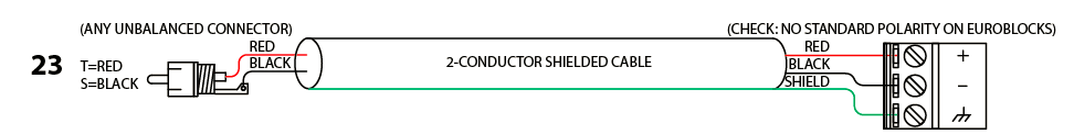
I am having the same problem as gepardcv, but with a slight twist. My amp is dead silent when volume control is fully off or on. But starting around 11:00, up to about 4:00, there is a definite hum that sounds like a grounding issue. So far, I just leave the volume at 100% and set volume level using my input device. But I would like to somehow solve this last remaining issue with my otherwise wonderful SRX-Plus build. I am using RCA connectors on my SRX-Plus amp, but the amp itself of course is balanced inputs. Here is the way I have it connected now: Here is how I have seen it recommended, but does not show volume control. This also does not address the issue of my volume control having a common ground/return for L and R, as well as my source having a common ground/return for L and R. Also, unless I tie I- to Gnd on the terminal block, I get massive hum and weirdness, whereas the recommended method below shows not tieing I- to GND. . Anyone have experience hooking RCA input to a balanced amp using a 3 terminal per channel volume control?
-
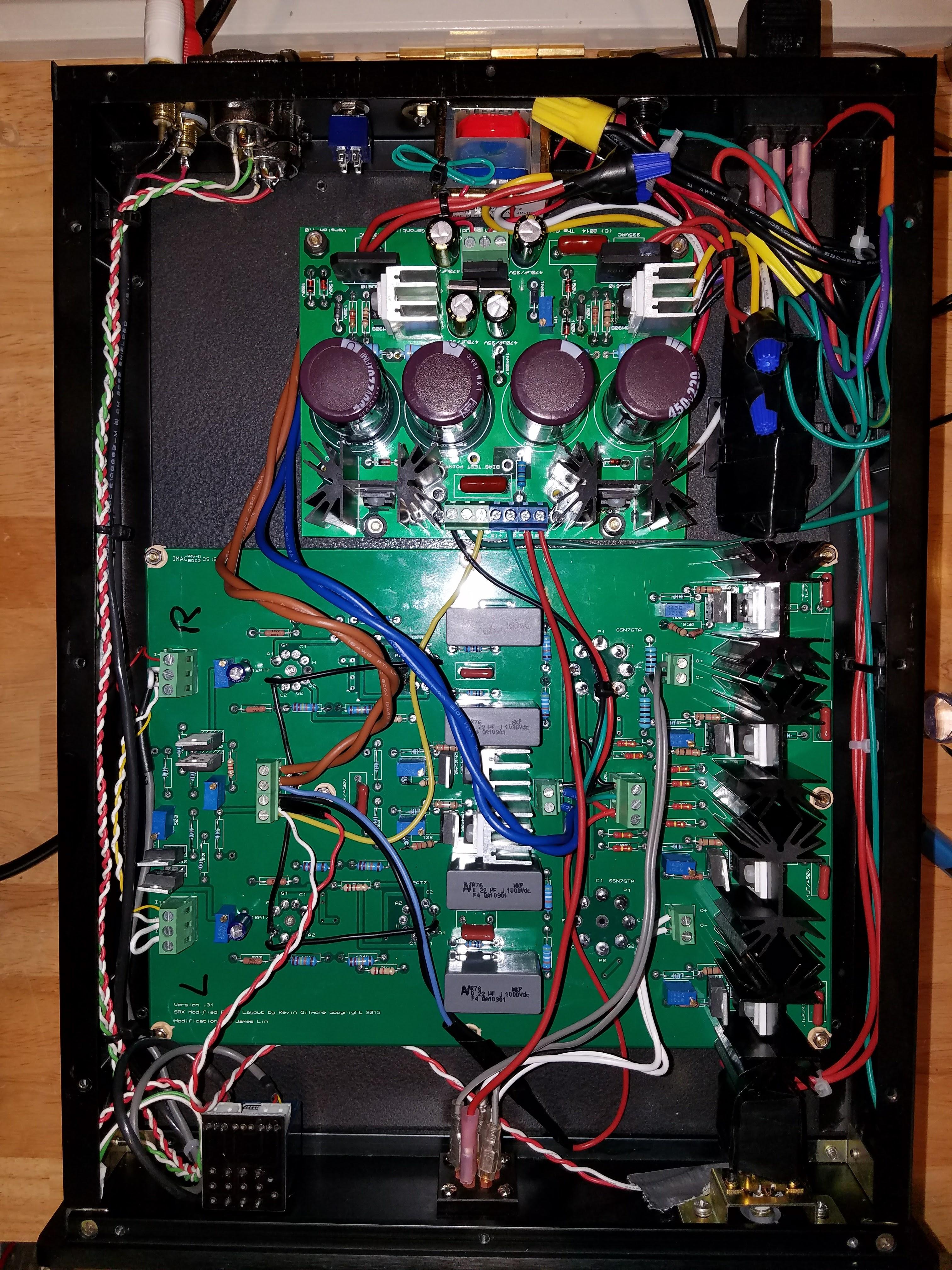
After swapping out the tubes with better ones (Penta Labs for 12AT7s and Tung-Sol for the 6sn7s, not pictured below) I was able to wipe every single bit of hum. There is still an issue when the volume control is in the 11:00 to 3:00 position where hum comes in, but for now I am just leaving volume at 100% and adjusting from the source. But I now consider this a successful build! The sound is a big leap up from the SRD-7 I was using. Thanks to everyone in the community who helped on this. James Lin for the design, the great article on AudioXpress, and overall thought leadership Kevin Gilmore for the board layout and guidance gepardcv for providing KGBH PSU boards and being so patient as I resolved the exploding zener diode issue! I owe you, man! mwl168 for doing the group buy and for providing endless guidance. congo5 for doing the early prototype build and showing just how good this design is. jose for doing one of the early builds and giving me guidance and most of all, to my son who came up with this project and did most of the soldering after my exploding zener experience!
-
Thanks, mwl168! I just took all the input wiring out and re-did it using info from your link and other posts, and magically it works!! Volume is smooth and quiet. Yes!!
-
Makes sense. And I agree, I do not get any pops or harmful signals coming from the headphones. I do like the idea of the filaments heating up before the HV kicks in. Jose, would it be better to put a relay on the HV lines from the transformer to the PSU, which are AC rather than the DC from PSU to amp? I tend to dislike switching DC due to arcing. Another issue I continue to have is the volume control. I have a ALPS RK27 50KA Audio Taper Potentiometer. I mounted it to a PCB that was supplied that gives a 3-wire in and out. The 3 lines are L,R,Ground. I am using unbalanced RCA inputs. I tied the 2 RCA grounds together and run shielded 3-wire cable from RCA to volume control. Then another shielding 3-wire cable from volume control to inputs. On the board, I have tied GND to I- for both channels. I connect the ground from the volume control to both channels (Ground and I-) and connect the hot wires to I+ of each channel. The result is a lot of noise and rhythmic clicking. Any idea what I am doing wrong? When I bypass this setup and connect the headphone jack of my phone (again, 3 wires with R+, L+ and GND) to the I+ of each channel and common ground to both inputs (each tied to I- on the board), it works just fine. BTW, I ran the amp for 6 hours yesterday. After 15 minutes it was dead silent with no hum. Temperature of the case maxed out at 38C, which I feel is reasonable. Sound quality seems to reach maximum level at about 15 minutes and does not vary after that. Really sweet sound compared to the SRD-7 I have been using for the past 2 years.