Blueman2
-
Posts
289 -
Joined
-
Last visited
Content Type
Profiles
Forums
Events
Everything posted by Blueman2
-
I have been hearing nothing but good things about true (beam tetrode) 6CA7s. Might have to give them a try sometime. I like the Tung Sol EL34Bs (pentode I think) I am using, however.
-
I agree that the servo on the BH is probably not necessary. It is fine after about 10-15 minutes warm up. But I love a challenge, and getting a servo installed on my BH sounds like as good a challenge as any. JoaMat is kindly giving me some advice and direction, and I will report back when I have a pair of servo daughter boards created and working for the BH (fingers crossed). Back on the topic of the BH BJT itself, it really is an amazingly pleasant amplifier. Yet I can't say what it is about the amp that is so good. A/B testing with my Carbon and SRX don't really tell me anything. I honestly cannot tell a big difference. Yet listening to the BH for an hour or two leaves me feeling so good, whereas the Carbon is a bit more fatiguing. Not saying the Carbon is not great, I just find it less suitable for listening to for a couple hours while doing other work. I find I am using the BH for my 'ambient' amp, where I want to listen to music for hours at a time while doing other tasks. I tend to use the Carbon for my 'critical listening' amp where I want to really focus on the music without other distractions, at perhaps a bit higher volume level. My SRX is a great amp for both use cases.
-
Correct. Right is Positive with Bias voltage supply, Left is Negative with low voltage supply.
-
You are correct! The sws adds an extra position for the SiC chip mounting hole which helps. So the sws version is the one to use. Files attached below... kgsshvpssicfetsinglenewleftfatsws.zip kgsshvpssicfetsinglenewrightfatsws.zip
-
I am getting quite a drift in offset for my BH BJT. To get it to zero out at full warm up (about 50 minutes), I have to start it at -45V on one side and -35 on the other. Balance stays good on both sides, starting around 3-4V but always getting to less than 0.5V at full warm up. In a discussion with JoaMat regarding Servo1 vs. Servo2 for Carbon, he mentioned it would be possible to do a daughterboard for the BH and tie it in to tame the offset drift. Looking at the schematics, the BH BJT and the Carbon (and for that matter all of the KG designed ES amps I have seen) share a very similar architecture, so transferring the Servo design should be doable. I think JoaMat did this successfully. Has anyone else done this? I was going to try to come up with a schematic for the daughterboard and how to tie it in to an existing BH, but wanted to see if I could leverage off the work of others first. BTW, if I am wasting my time worrying about the offset on the BH, please tell me. Or if there is another way to attack offset, I would be curious. I moved tubes around and that did not seem to make much difference. Big thanks to JoaMat who gave me nice background and tutorial on the Servos.
-
Actually, I meant the split boards. The FAT version is still the 2 separate right/left boards, but is the fatter version as compared to the skinny version that is made to mount vertically onto the heatsink. I prefer working with the FAT versions. The attached files are I think the right ones??? But we need to confirm. There are also versions of this board that have an extra 's' at the end, and I am not sure what that extra 's' means. And I am not positive this is the most recent version of the GRHV. Perhaps Dr. Gilmore can let us know. kgsshvpssicfetsinglenewrightfatsw.zip kgsshvpssicfetsinglenewleftfatsw.zip
-
I am referring to the HV PSU boards. I don't think the Unbal-to-bal board would use 400V would it?
-
Thanks. Sorry for my confusion on the OpAmp. But is there any advantage to engaging Servo2 rather than Servo1? As I recall, only one should be enabled at a time.
-
I currently have the Op27a based servo (Servo 1) in use on my Carbon. Works great. I just got hold of a couple 4N25's for the Optocoupler (Servo 2) and was going to plug them into the board. Is there any advantage to the optocoupler servo over the op-amp servo? Just curious why both were put on the board. For now, I am leaving Servo 1 enabled and Servo 2 disabled.
-
If you are able to get enough people for the GRHV, I prefer the individual Fat boards with opto switch (e.g. kgsshvpssicfetsinglenewleftfatsw and kgsshvpssicfetsinglenewrightfatsw).
-
So which boards are you considering in this group buy? All that are listed in the spreadsheet, or just some of them?
-
Not sure if any members have extra SRX-Plus boards, but you can have one made, try to start another group buy, or just do point to point wiring. Attached are the board files. Group buy was SRX6 version, as I recall. Check the thread to see what the rev2 changed. srx6.zip srx6rev2.zip
-
OR.....

-
Yea, that must explain it. I had been warned that the BH BJT runs really hot, so was expecting more heat from it. So far, it is maxing out at 39 °C on the heat sinks, and 45-48°C on hottest silicon. Carbon is running 3-5 degrees hotter. Of course, both cases have pretty large heatsinks due to single PSU/AMP case design, which probably helps. <FEAR> Nooooooooooooooooooooooooooo! </FEAR> Must resist even reading Megatron thread. Must repeat to myself: I do not need another amp. I do not need another amp. I do not need another amp......
-
In case anyone should want to know, I measured the power usage for the Carbon, Blue Hawaii and SRX-Plus. SRX-Plus (using BHUltraMini PSU @ 350V) = 53 Watts Carbon (using GRHV PSU @ 400V) = 92 Watts Blue Hawaii (using GRHV PSU @ 375V) = 140 Watts
-
I am not good at putting words to what I hear, but let me give it a try. This is on my SR-007 with blu-tak mod. The Carbon is more crisp, but more 'in my head' in terms of sound stage. The Blue Hawaii has more body and a noticeably wider sound stage. While the Carbon appears to highlight higher frequencies, I find that cymbals and the metallic 'sizzle' sound of a snare sound better on the BH than the Carbon. Backward from what I expected. The reason I tend to really like the BH is that it excels at warm and full, but does not sacrifice high frequencies and fast transients in any way. Its ability to do both so well is what struck me the most as I started to get used to it. I can make the BH sounds more like the Carbon and vice-versa by using frequency equalization in foobar player. So it appears much of the difference I hear is related to which frequencies each amp peaks on. It is also interesting that I was expecting the Blue Hawaii to sound more like the SRX-Plus since they are both tube amps. But I find the SRX is just as different from the BH as the BH is from the Carbon. 3 very different amps. With flat equalization, I tend to like the BH best right now. I listened to the BH for 1 hour, then the Carbon for 1 hr. Not scientific, but I just enjoyed the BH better. As JimL has said, it is always the new girl who gets the most attention, and perhaps that is what is going on here. After building the Carbon, I felt it was better than the SRX, but after a few weeks I found myself using both pretty much equally. I am very happy with these 3 amps and am indebted to this community for all the help in choosing and building them. I am also glad I have all 3 because they are all different and great in their own way. EDIT: FYI, my source is a Gungnir Multibit ('Gumby') using balanced out into both the Carbon and the BH. Now on to more listening.....
-
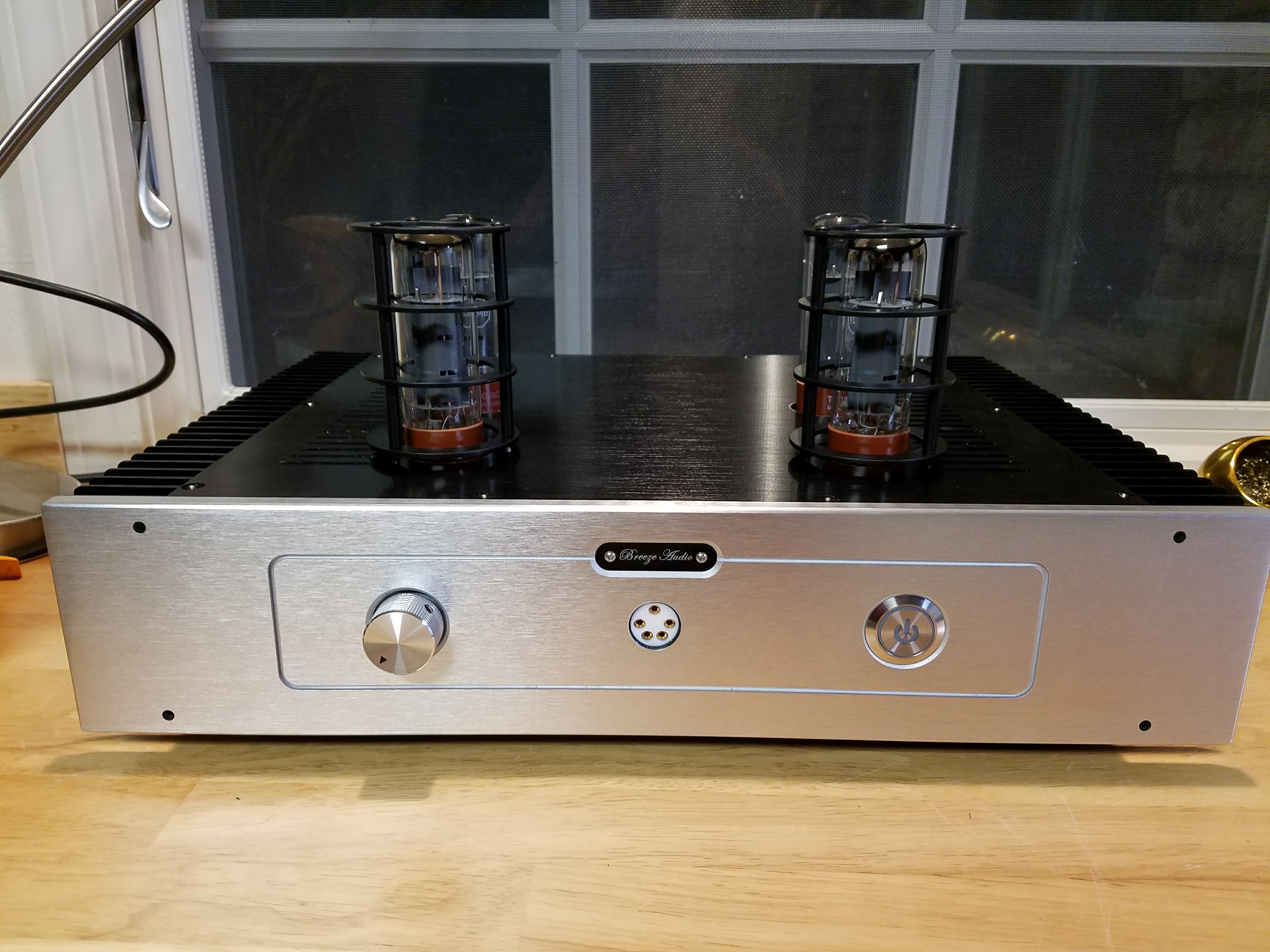
The case is available in several configurations from several sellers on eBay. Search on "BZ4309" or just "4309 aluminum chassis". Mine was a great price: $110 including shipping and arrived from China in 4 days! Seems like the price jumped to $150 or more now, so I was lucky. The holes are for rack mount front handles. I did not like the look and plan to tap holes and put aluminum screws in the front to cover the holes.
-
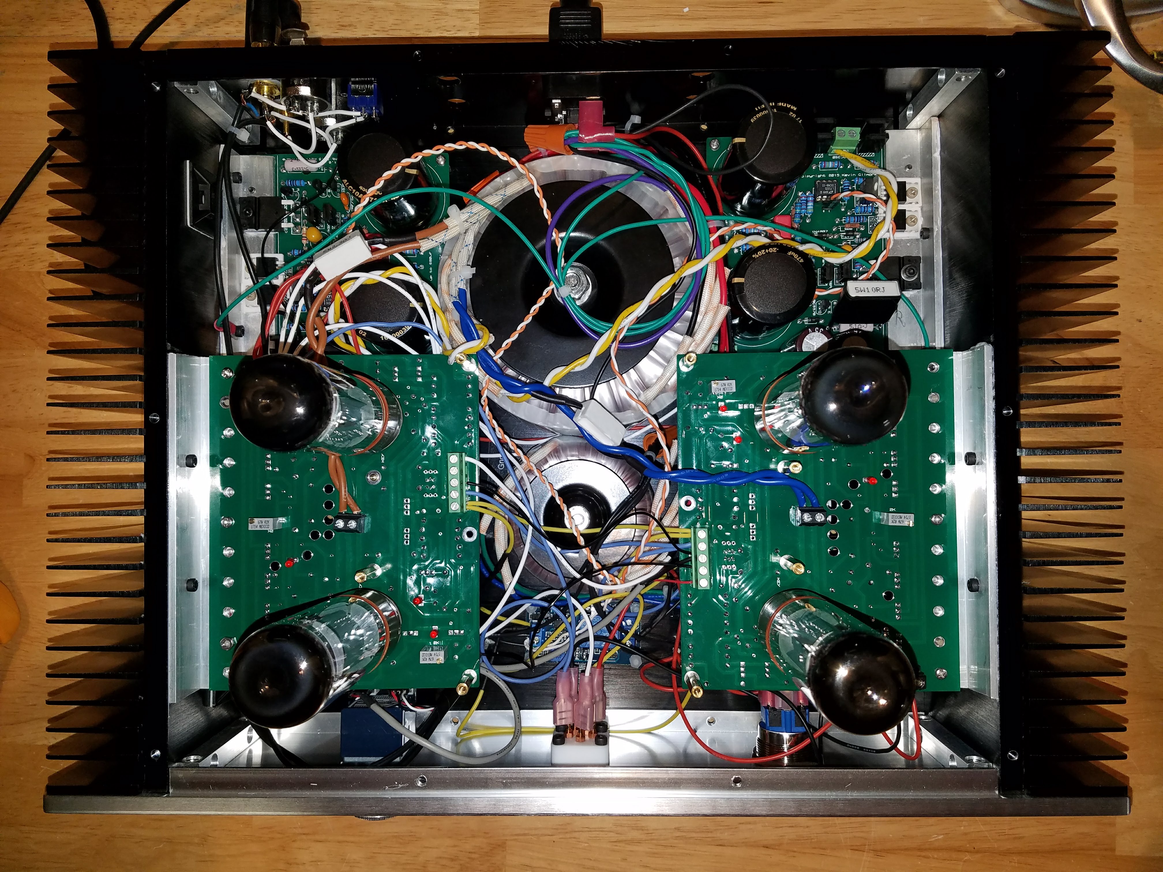
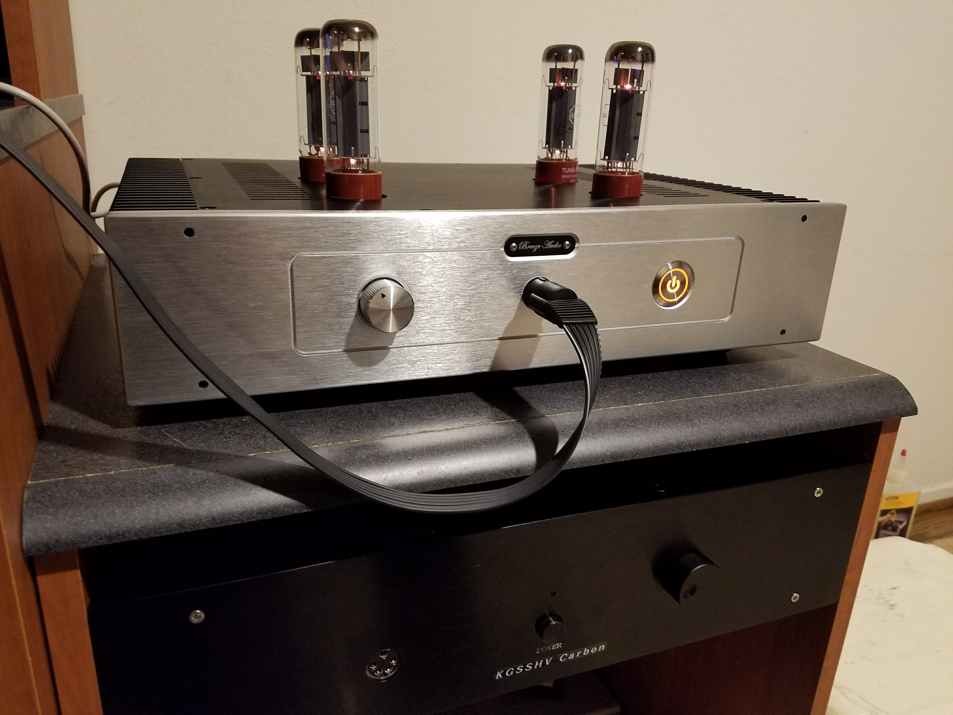
Got the filaments down to exactly 6.0VAC using 0.3R 5W resistors. B+ and B- are both solid now as well. +375V and -378V. About 0.2 drift over 30 minutes of warm up then stays fixed after that. Still comparing to my SRX and Carbon, but the sound is certainly glorious! I know, pics or it didn't happen. So.... Above, you can see that in order to make this fit in a 300mm deep case, I had to create 2 layers of boards. PSUs on bottom, Amps on top, with about 30-40mm of overlap. There was actually plenty of clearance and I could have moved them to overlap even more if needed. I was able to leave enough room in front for the power switch and future quad pot when it arrives. Please don't give me too much crap for the messy wiring. I plan to take it apart next week to add the quad pot and clean up the internal build a bit. I just wanted to prove to myself that it would fit! Also, notice that I am using the 755-SCT2H12NZGC11 as a replacement for the C2M1000170D for the PSUs. It appears to work just fine and runs cool. So we do appear to have a backup device for when the C2M1000170D SiC is out of stock. Also, in the front middle (under the mess of wires) is a timer delay for the CPC1117 HV delay turn on, as referenced earlier in this thread. I have it set for 60 seconds. Above with the tube cages. I have not install yet, but just wanted to see how they will look. That will be next week... And finally, sharing some room with my Carbon. Not pictured are my SRX builds (one mine, one my son's). BTW, so far, the BH runs cooler (both case temp and silicon temps) than my Carbon. Both running at 20ma.
- 242 replies
-
- 10
-

-
Running like a dream now! Thanks mwl168 and sorenb for the fixes. I reduced the amp to +375v and -378v by overlaying 4M7 resistor in parallel to the 390K ones, and it is holding rock solid. Loaded or unloaded, same numbers. And with the 2R6 on the B- current limiter, it is handling the 135ma on that rail without issue. I did not have to change the B+ side current limiter. Frankly, I would never have solved the current limiter issue without your guidance, mwl168. Just spent about 10 minutes on the BH using some older Lambda Pro's that I use to test amps (if they get fried, I will not cry). Now to plug my 007's in and lose a couple hours of time....
-
Thanks. Is there much of an issue running a BH BJT at only 375V? Either that or I will get a 350V rated trafo. Just not sure the larger trafo will fit into this case. Things are really, really tight in there right now.
-
Details are: Raw AC from trfo: 2x 315V @ 330ma each Unregulated DC: 436V Regulated B+: +404 no load, +392 load Regulated B-: -410 no load, -383 load SiC drain is 8.3V under load. will measure other in a bit... Thanks sorenb.
-
I am moving the discussion from Carbon thread to here since it is more related to Blue Hawaii. Here is the prior discussion: I did not realize that the BH demands more current than the standard GRHV is set for. There is a 5R1 resistor in the GRHV that needs to be changed to allow it to provide enough current for the BH BJT. I am measuring current of 83ma on the B+ and 134ma on the B- on my build. B+ rail is fine, but I had to reduce the current limiting resistor in B- from 5R1 to to 3R in order to get enough current to drive the BH. Moving discussion here so that others can learn from my error.
-
Ah, I was not understanding how the current limiting resistor works. Looking at the schematic, does it give a reference voltage for the 2n3904 and that feeds back to the C2M? Doh! Sorry, mwl168, I was being dense. Now I understand the importance of that resistor!! Out of curiosity, how do I calculate the current limit imposed by the R11 (the current limiting resistor) in the circuit? What limit does the existing 5R1 impose? EDIT: Partial success!! I changed the current limiting resistors to 2R5 (paralleled 2 5R1s as mwl168 mentioned) and things did get better. Voltages no longer drop off over time. But bad news is they are still both around 390V, and fluxuate a bit as household devices such as refrigerators turn on/off. But stays in a range of about 390 +/-3v. Enough to allow me to get offsets down to under a volt and confirm the outputs to 20ma. As for the low voltage, I think I will now replace the trafo with one I have in one of SRX builds and see if that helps. Thanks mwl168 and mypasswordis!!!! Both for your guidance and your patience as I learn along the way.... EDIT2: Oh, and I could not resist giving it a try.......WE HAVE MUSIC!!! And sorry for polluting the Carbon thread with what turns out to be Blue Hawaii BJT issues. There was more discussion on the GRHV boards here, which is where I was guessing my issues where. I am moving the discussion back to the Blue Hawaii BJT build thread. EDIT3: Just for future reference, it appears that the SCT2H12NZGC11 does indeed work as a replacement for the C2M1000170D, so we appear to now have a backup when those go out of stock as they seem to do pretty often.
-
BTW, I am measuring 0.68V across my B- 5R1 resistor. So about 133ma, about what you predicted for B- rail. The voltage then drops slowly over time across both the current limiting resistor and the B- output itself. I am still of the mind that either the trafo is not keeping up or the SiC chip I am using is not working in the same manner that the original C2M was designed. And given the dropping unregulated voltage, I am thinking trafo issue. (see below; current limiting resistor is more likely cause, or at least, a contributing factor)
-
I am using the 5W 5R1 resistors. But not sure that explains the drop in unregulated voltage I am seeing. For the 5R1, is it the wattage or the value that needs adjusting?