Blueman2
Returning Member
-
Joined
-
Last visited
Everything posted by Blueman2
-
Holy cow!! That is a gorgeous build!!! Freaking gorgeous!!! Congratulations. I had not seen a build with quick disconnects for the tubes before. Very cool. Why did you go that route vs building the boards into the top directly? Just curious as I embark on my very first build.
-
Fixed.
-
What is their typical turn around time? My 507's just arrived today and I can't wait to start the build!!!
-
mwl168, How is the progress going on getting funds collected and boards ordered? Let me know if there is anything I can do to help. Especially if someone drops out, I am willing to take up the slack until a buyer comes in down the road.
-
I added a Bill of Materials to the first post for the SRX-Plus amp. Anyone else who is looking to build, please let me know if you see any errors or omissions. I will keep the first post updated with the correct BOM.
-
pongo5, do you have any more pictures of your build you can share? I would like to see it along with the other components, and how you mounted them into a case. And what case you used! Thanks. Blueman2
-
-
OK, just to show how much of a noob I am, I did not know that the tubes were mounted opposite to the components! Is that to allow the tubes to fully penetrate a case top? Or to prevent the heat of the tubes from impacting nearby components? Or both? I will need to rethink my strategy for the case for this system. I was going to repurpose another case I already had, but this might change things. I will need to hunt around for pictures of how others have done this. Maybe mount this onto the TOP of my case rather than the bottom, and use a bit of extra wire to the inputs, outputs, and power supply to allow for the top to be removed. I need to research on how others have done this.
-
Sent. BTW, did you mean $6.10 for shipping costs? That is what I sent, but wanted to confirm.
-
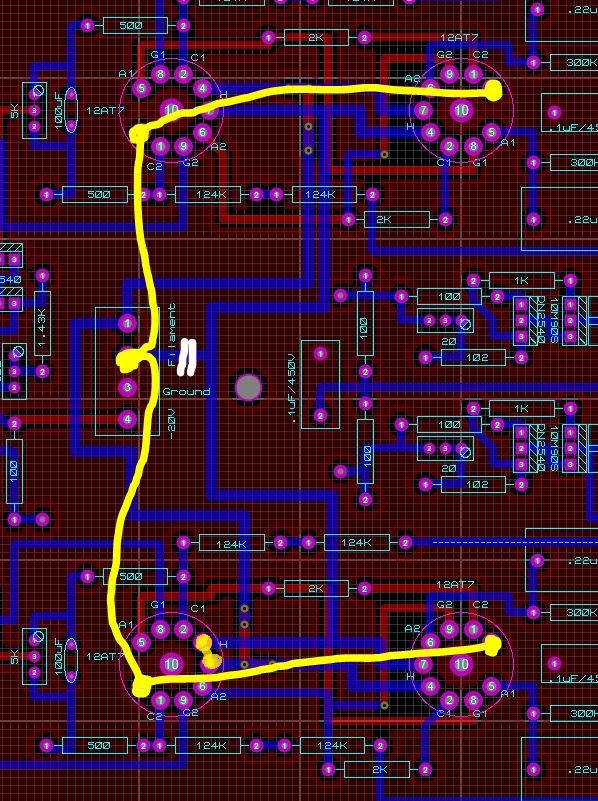
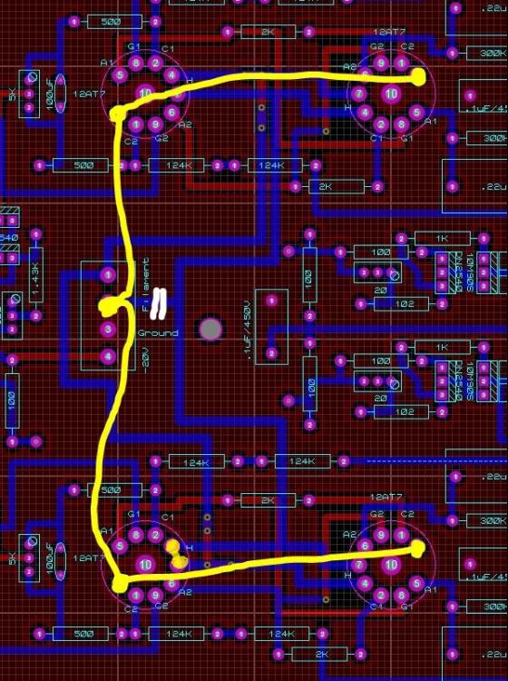
Just to make sure I have this right, I was planning to CUT the trace going to connector 2 labeled "Filament" on the SRX6 board. Then run a wire from each pin 9 of the 12AT7s, and run that to connector 2. Then I would also have to short one of the 4-5 pins of one of the tubes so that all tubes would have 4 and 5 shorted together (in the diagram below, I shorted 4/5 on the lower left tube). So pin 9 gets one side of the 6.3V, and pins 4/5 both go to the other side. That right? Note: for the 12AT7s, I am using the normal tube numbering for the pins, so ignore the numbering in the SRX6 layout below. Not sure why they are different. So pin 1 is A1, then clockwise from there.
-
Thanks again. I was wondering why 9 was not connected to anything. I think I will do some soldering on the board to add a connection to Pin 9, and just use my other 6.3V winding. Now I am back down to just 1 transformer. Yeah! Any recommendations for the Volume Control that I assume goes before the inputs? I know one can drop a lot of cash on these attenuators, so just looking for something that is in line with the cost of this overall build. Is something like this acceptable?? Stepped Attenuator Log 100K
-
Cool. Thanks Jim. I was going to put probes on this anyway to reconfirm what is necessary for the 20V, but will start with 150K off the -350 rail. Yes, I was going to use the 300K plate resistors per the KG board. And what is the advantage of not letting the filaments float in your design? Just curious to learn. BTW, you mentioned that you somehow used a 6.3VAC winding to drive the 12AT7 tubes in your original design. How is that possible? They need at least 12V don't they? Or did you uplift the voltage somehow using diodes? Just curious to see if I can still use my 2x 6.3VAC windings to drive everything, or if I will just bite the bullet and get a 12.6V transformer too.
-
OK, I have assembled all the parts for a KGBH PSU build to go with one of the SRX-Plus AMPs. I plan to build 1 AMP with KGBH PSU and 1 AMP with JimL's shunt PSU. Just to see the difference (If I can tell any difference!). One will stay with me, one will go to my son. I was asking questions about build in the SRX-Plus thread but decided they belonged better here so as not to pollute the SRX-Plus design thread. Sorry JimL for taking you down a rabbit hole in that thread! Soooo. I am using the kgbhultraminipsv4 PCB for my KGBH PSU. There are 2 things I am having to deal with using this PSU for the SRX-Plus. B+/B- output. The kgbhultraminipsv4 PSU board says on the silk screen 350V. But it has zener diodes listed as 100,150,150 on each rail. That adds to 400V. Is that a mistake on this board? I could not find any threads specific to this board talking about this issue. Also, KG's SRX6 board lists rail input of 340V. Is 350 close enough or should I add a 90V zener in place of one of the 100V. -20V output. The SRX-Plus requires -20V for the input stage tail constant current sources. In JimL's design, he used resistor(s) from the -325V rail, calculated based on the current draw of both the channels, to get to -20V. My KGBH PSU does not have that and, as mentioned above, will be at -350V on that rail. I guess my options are: add a resistor (I think 143K ohms would do) from the -350V rail to create the needed -20V input on the SRX6 board. JimL, how sensitive is the CCS to exactly 20V? Or is +/- 10% OK?? I could use the unneeded +/-15VDC curcuit on the kgbhultraminipsv4 PSU board, replace the 7915 with a 7918 (there is no 7920 that I can find!) and use the -18V output. I think -18V is close enough to -20V (??). The advantage of using the 143K resistor off -350V rail is it saves a transformer and some devices (7918), so I will probably go that route. I plan to still use a 7905 or 7912 for +5 or +12V in order to drive power LED and a fan for my case.
-
It just hit me that I am asking a lot of build specific questions in a thread that is more about the SRX-Plus design. Sorry about that. Mods, maybe move these to the Plan to build SRX. Where to find BOM, Boards? thread? I will continue my questions over there.
-
OK, I made a mistake then. I should have seen that the 12AT7s needed 12.6V and the 6SN7GTA needed 6.3. But in my mind, I had thought both were driven by 6.3. So the 2x 6.3V transformer I bought will not be enough. I cannot just combine the 2x 6.3 for the 12.6V, right? (Since one leg of the 6.3 is driving the output stage). So I will need to buy another 12.6V transformer to drive the input stages(?) Would a single 25.2VCT transformer be OK to drive the 12.6V input stage filaments as well as providing 25.2V for the -20V supply? I was not sure if there would be any issues with one winding of the transformer being used for the 12AT7 filament and the -20V supply at the same time.
-
I see in your article on AudioXpress, Figure 3, that you only had one such circuit for both input stages. But the srx6 board layout has separate circuits for each channel. Is that something Kevin added for balancing reasons? (EDIT: Doh! I misread the schematic. Nevermind). If do go with B+/B- of 350V, specifically which resistors should I change? Alternatively, I can just put in different zener diodes and drop my KHBH PSU to +/- 325V. Which would you do? I already found a nice toroid transformer that can drive up to 400V if needed (it is 2x 350V), so that is not an issue.
-
mwl168, If we end up being below 20 boards on either the AMP or the PSU, I will agree to buy the amount needed to get us up to 20 boards. Otherwise, I confirm my commitment for 2 of each board.
-
JimL, I have spent a few days reading, and am learning a lot! I see on your board design you have separate Filament inputs for 6SN7GTA and 12AT7. One labeled "F F" (for the 6SN7GTA tubes) and other labeled "Filament" (for the 12AT7 tubes). I assume each gets 6.3VAC from separate windings on the transformer, as you alluded to above, right? Also, with respect to using the KGBH PSU (kgbhultraminipsv4 design) with your AMP. Sounds like I can keep the default +/- 350V outputs. But I see near the "Filament" input for the 12AT7s a -20V input and GND. What is the -20V for? Is that simply to drive the test points? The KGBH PSU does output -15V. Will that work? Or should I replace the 7915 in the KGBH PSU with a 7920 and use that output? Also, do I even need the +15V for anything in that case? Maybe I could use a 7805 and get +5v for led or other usage?
-
mwl168, Any chance of going forward with the GB for just the amp? I think some people (like myself) might go with another power supply for now. I got hold of a BH PSU board and plan to start building that very soon. It would be great to the the SRX-plus boards so I can start that as well. Thanks again for be willing to lead the board buy. Blueman2
-
Does anyone know a good source for female 5-pin pro-Stax connectors?
-
Agreed. I am still torn between the StaxPlus PSU and the KGBH PSU. I prefer to go with whatever is smaller and easier to build/buy parts for. But I will absolutely commit to 2 sets of whatever boards are in the GB.
-
Thanks once again Jim. You are very generous with your time and advice. I appreciate it.
-
Jim, is this for the Amp or the PSU?
-
Thanks Jim! Especially for pointing out the need for 2 6.3v windings. Most transformers have that, but one I was going to buy did not, so you saved me from wasting time/money on that one. And to confirm, a 1000vct is OK, right? Just gives more headroom for brownouts (which we sometimes get).
-
JimL, Thanks again for sharing this and for the great article in AudioXpress (I subscribed for a year just for your series of 2 articles!). I had a couple questions as I started to bring parts together. - For the transformer, is the 5v tap needed? I can more easily find 800vct and 6.3v taps, but more rarely do they also include 5v. - Is a larger cvt OK? I found a very nice 950vct 140ma transformer with a single 6.3v 2A tap. Would that work OK? - in your image above, I see a LOT of big iron in that thing! Big grey box to left certainly looks like a transformer. What about the darker grey smaller box and the 2 beige boxes to the right of those? and the black box to far right? Finally, Jim, is there a simpler power supply I can build for your SRX-plus amp? Something perhaps smaller and solid state only? Just curious what my options are for power supplies. Thanks for helping a newbie come up to speed. Blueman2