Blueman2
Returning Member
-
Joined
-
Last visited
Everything posted by Blueman2
-
TLDR Update: The replacement part does indeed work just fine! I have it running in the power supplies of my Blue Hawaii without issue. Comments below were before I figured out some other issues I as having. Well, things did not blow up, but I have run into a problem using the part. I tested both PSUs and they tested fine unloaded. +404 and -410. I then loaded with 15K 20W resistor on each supply, and the voltages held perfectly. I then hooked up to a new Blue Hawaii BJT I am building, and each side of the BH worked, though voltages did drop a bit from the +404 and -410. The B- was the most impacted, dropping to -400 but still working. I then hooked up both sides of the Blue Hawaii and voltages on both B+ and B- dropped by several hundred volts. My conclusion is that the new part is for some reason not able to keep the current levels I need. What surprises me is that PSUs could drive the 15K resistor without any issues at all. I guess the Blue Hawaii BJT demands a heck of a lot more power than the 10 Watts demanded by the 15K resistors. I will try loading both resistors on B- rail (so 7500 ohms) to give that rail a 20W test. But at this point, it appears my gamble did not pay off in using the alternative part. (This was a wrong assumption. Apparently the part is just fine. Read about 6 posts down) Was worth a try I guess!! EDIT: Loading the 15K power resistors in parallel (doubling the draw to 20W) did drop the voltage down about 2 volts on each rail (to +402 and -408). So that should not happen, right? I do not have any lower value high wattage resistors to test with, but clearly something is wrong with both PSUs, and probably the part I used SiC. Only other possible issue could be the transformer. I will double check unregulated voltage to see if that is staying stable.... EDIT2: Well, maybe it is the trafo?? Trafo is giving 312 VAC on each side. Unregulated (after rectifier), I am measuring 436 VDC on both sides. When loaded, the Positive side unregulated voltage drops to 395 for a second then recovers to 407. The Negative side unregulated (which takes the most drain when using a Blue Hawaii) drops to 390V then recovers to 393V, and then slowly drops from there. Clearly, the trafo is not keeping up. It is a brand new one from Antek. I measured about 50VA HV load from side of the Blue Hawaii. The trafo is rated for 100VA per side, so I do not appear to be exceeding the trafo rating. I think I will pull a trafo from one of my SRX-Plus builds to see if I can confirm the issue. Maybe I was too quick to blame the replacement SiC?
-
Thanks guys! Just ordered a 10 pack of 0.3Ω 5W resistors and will get that voltage down to 6.0V - 6.3V range. You see any harm leaving at 6.8V for now until I get the parts? As mwl68 says, that is still within 10%. Just barely. EDIT: I did find the spec sheet on the Tung Sol EL34Bs I am using. It gives Filament range of 5.5-7.0. So I guess I should be OK with limited use until my resistors arrive.... el34b-tungsol.pdf
-
Hmm. Then more like a 0.3Ω resistor is called for. Or, if I am willing to live with a bit shorter tube life, is 6.7 to 6.8 VAC something I can live with without reducing? This makes me realize that my 2 SRX-Plus amps are probably also being driven too high for filament voltage.
-
I got the BH BJT up and running today. Everything seems great and I was able to dial all the voltages and currents in just right. One issue I am seeing is filament voltage. My Antek PSU is giving me 6.8V under load for the EL34s. Our voltage here is always around 125V, and the PSU was rated for 115, thus the higher value for the 6.3 feeds. I put a pair of 5W 1Ω resistors in parallel to create a 0.5Ω resistor for each amp board filament supply. That got the voltage down to 5.5VAC. Is that too low or should I go out and buy another 1Ω resistor to add in parallel?
-
-
Not sure I would want to run this when the LV is not working correctly. I would wait to get that nailed before even powering the Carbon boards. For the LV trafo, it is a 2x16, right? For me, it DID matter which wires you put together for the CT connection on the board. If it is right, the other 2 will measure 35V or so. If it is wrong, they will measure only 17. Try that. I will say I like the Molex connectors. Never seen that before and it has some real advantages. EDIT: Yes, I just checked my amp, and I had Color1 to one 15V, Color2 to other 15V, and Color1/2 together on CT. It looks like you have it different?
-
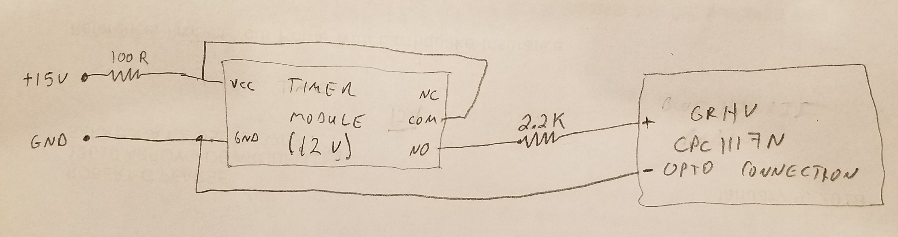
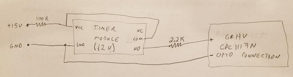
For the delay start of HV on the GRHV boards, what value resistor should I use for driving the CPC1117N Opto using 15V? The spec sheet was unclear on this, but I was assuming I should add a 3K or so resistor (?). EDIT: Well, to answer my own question, I was able to find the forward voltage drop of the diode in the CPC1117N using my meter. It is 1.2V. So with 15V supply, that leaves voltage of 13.8V to get rid of. The turn on amps for the 1117N is 1ma min to 50ma max. Assuming 10ma as a safe target, I get R=13.8V/.010A=1.38K resistor. Since 2.2K is a common value, I will go with that which will provide about 6ma current to trigger the opto relay. EDIT2: Yes, these values worked fine. Here is a crude drawing of the circuit. I am measuring about 5ma to the CPC1117N input, which is about what I wanted. A 3K resistor would probably work just fine as well and would lower the current even more to the CPC diode. I am using THIS device, 12V version, from eBay as the timer. It works great for this application and is cheap. I have it set for delay on of 60s. You can also put jumper on S5 on the device and it will provide the VCC without the additional wire from Vcc to relay COM.
-
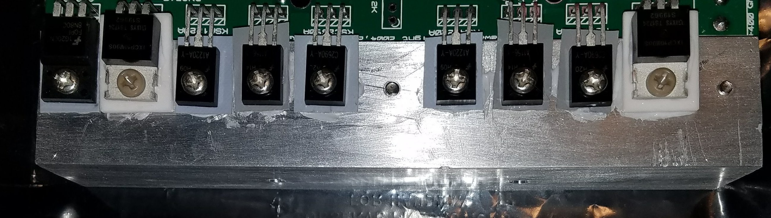
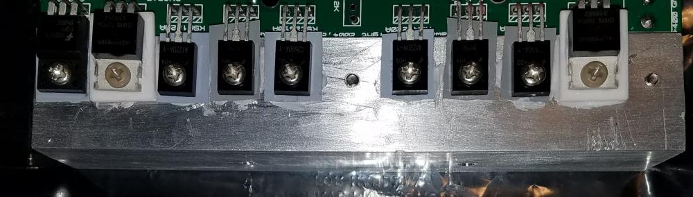
For the silicon that connects to the offboard heatsinks, are the 10M90S's the only ones that require aluminum oxide pads and non-metallic peek screws? Everything else appears to be fully encased. The 8N80C even appears encased and might not need the aluminum oxide pad and peek screws (?). I wanted to confirm before I soldered those on..... EDIT: Here is what I have done for pads. Al oxide for the 10m90s and silicone rubber for the rest.
-
Birgir, I saw this on your home page! Just came here to ask if you have any thoughts of producing a few for sale? EDIT: nvrmnd. I see you are indeed selling these. Turning a friend onto this one.....
-
No fixed resistor; just the trim pot. Good to hear the 2K is still running for you. Since I will be a bit higher than you in my KSA1156 emitter resistors (200R vs your 150R), thus lower in current to the 3rd stage, I should be OK. I will report back once I have this powered up, in about a week I think.
-
Thanks. Since I can only go with 1K or 2K trim pots (no other ratings available on this package) I will leave the 2K in, measure the voltage across it, derate it given it's resistance %, and see if it is OK. Assuming 500R setting on the 2K trimpot, that gives derated power of 1/8W (1/2W full rating * 500/2K). That means I can have max of 8V across the trimpot if my math is correct. At 750R setting, I can have about 11.8V for max ratings. We shall see!
-
I plan to use 200R resistor and see how that plays out. Since I am using pretty large heatsinks (90mmx300mm, 50mm long fins) I think I should be able to handle 10-15ma no problems. To measure current to the 3rd stage, do I just measure the voltage across the 200R resistor I will be using and divide by 200? I will measure the voltage across the offset pot to determine current flow and power (my pot is rated at 1/2W power and 100ma across the slider).
-
Very cool! Congratulations on the build. And the Mechanical Engineer in me loves seeing that dainty little circuit in that massive bench clamp.
-
Ah, I had my terminology wrong then. So soft start refers more to limiting the current going into the filaments (or others parts if desired?) to lengthen tube life? Whereas the delayed HV is another separate option in order to avoid the offset spike?
-
Thanks sorenb! I will just stick with soft on and adjust to 60 seconds. And since my mains run about 125V here (vs 115 spec for my trafo) I will add a power resistor to the 6.3V to get that down to 6V. ??
-
Sorry for the number of questions here, but I was researching soft on for the BH and wanted to confirm my understanding. I plan to use a 45 second delay between the time the 6.3V filament and +/-15V LV start to the time the +/-400V starts. Based on my experience with the SRX-Plus, this seems reasonable time to allow the voltages to settle a bit. But I also notice on the SRX that the offset spikes to around 300V when turning off as well. Not a problem since the spike is equal across O+ and O-, but still it is a spike. I was considering a soft-off option, which the CPC1117N opto relay should allow. I had 2 questions about that: 1) Is it necessary or common to have soft stop on the BH? I am hoping I do not need this. 2) How the heck to implement it, if needed? Soft on is easy. But soft off will require an always on LV power supply so that when I press a momentary switch (I think momenary would be the way to go), it triggers the right action on relays. Anyone done this? I prefer not to have a soft off if not needed, but just was not sure. 3) I also suppose if needed, I could drop the timer device and just have a 3 position rotary switch, with Off/WarmUp/On and just manually do the warm up and cool down cycle. Thanks for everyone's patience with my learning curve. Bob
-
Thanks, sorenb! I also noticed 2 part value changes. Older board without the relay used D1 zener of 10V, whereas new board is 12V. Also, old board used R6 value of 30K, whereas new board uses 50K. I am guessing I am fine using the 12V zener and 50K resistor on the old board? Since nothing else changed, I assume it was just some tweaking done during board revs. Oh, and brilliant idea using D1 legs to mount the tiny board on the main board. I am going to do just that! Plenty of vertical room since the Caps are so high.
-
I need some advice on modifying a GRHV board that does not have the delay circuit (no CPC1117N). I want to add the delay circuit to it for use with the BH BJT I am building. It appears from looking at the attached diagram (for the board with the CPC1117N) that the delay circuit effectively puts a 600R resistor across the 12V (or 10V on my older board) zener D1 to shut down high voltage output. Is that all that is needed to shut the board down? I plan to make an off board circuit using a 600R resistor on the output of a CPC1117N, and tie that output across the D1 using about 6" of 20awg wire. The CPC will be driven by a timer circuit I got off of eBay. It seems pretty straightforward, but I wanted to see if my thinking was valid. goldenreferencehvsic.PDF
-
-
So is this BH to be run at 20ma, so that the R50 test resistor will read 1V? Assuming I have really good heat sinks, of course.
-
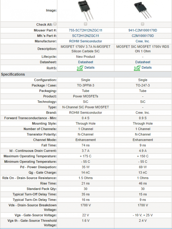
Pinouts match, and TO-3P appears to have same pin spacing as TO-247. I am going to be a guinea pig and give it a try. What could possibly go wrong? EDIT: Well, sorenb was correct! The part did work just fine and is now powering my Blue Hawaii BJT build. It appears to operate just like the C2M1000170D. Does not get very warm at all, either. The packaging is a bit different in that the hole is not are far down from the top as the C2M. This means that it can go into the same hole spacing as a normal TO220, rather than the hole that is lower down for the C2M (notice the boards have 2 holes that almost overlap).
-
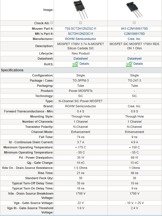
<Despair> noooooooooooooooooooooooooooooooooooooooooooo! </Despair>. Wait many days and many hours to build my 4th amplifier, of which I only really need one? Clearly you have overestimated my maturity and patience. Seriously though. For the PSU, I wonder if the 755-SCT2H12NZGC11 would be an acceptable substitute. Just not sure how much of an issue the lower current rating (3.7A vs 4.9A) and slower fall time will be. It figure it is always nice to have a backup source part for when the primary part goes OOS. Here is the parts comparison: EDIT (Aug 4, 2018): now running this amp for over 6 months using the 755-SCT2H12NZGC11. Working fine for me as a direct replacement for the C2M1000170D.
-
Thanks, joehpj! Only issue with 5W zener is that the leads to not fit in the board I had. I could have drilled it, but decided path of least resistance was to use a 1.3W version I had on hand. One can never have enough zener diodes!!
-
I was about to pull the trigger on another set of GRHV boards for another project, but see that the C2M1000170D SIC MOSFETs are out of stock at Mouser and Digikey. Would this part work as a replacement? 755-SCT2H12NZGC11. Biggest difference is the much slower fall time (74ns vs the 9ns for the Cree). Thoughts? Alternatively, I have a couple FQFP8N80C's on hand as well if those would work. Again, this is for the GRHV PSU, not for the amp itself.
-
Thanks, everyone! I put in 1/2W for the 470R and will test the temperature once I get it running. And I have handfuls of the 1.3W 100V zener, so glad that will work! All I need to do is order another couple R2k trimpots. mwl168, earlier in your build notes, you mentioned: Does the 3ma vs 10ma have much sonic impact? I am going to be driving a set of -007s and they tend to want <JeremyClarkson>More Power!</JeremyClarkson>. Just curious if this makes any real difference beyond heating up the room more.