

penmarker
-
Posts
138 -
Joined
-
Last visited
Content Type
Profiles
Forums
Events
Posts posted by penmarker
-
-
Nope nope guys shit. Sorry I feel so dumb. My biasing technique was wrong. The offset is fine. It goes below 40mV easily and the servo lowers it down to 0mV and maybe fluctuates a bit between 4 to -4mV
-
10 hours ago, hy2a3 said:
Head-Case.org amazes me. Just added to my religious lexicon.
Anyway, Is Dr. Kevin Gilmore's KSA5 Gerber file locked away in a vault? Can't seem to locate the gerber zip to build a single board to myself. Will cost $$$, but I need to do this right avoiding the Chinese clone temptation. Help anyone, if the zip is still open to private use (not commericial).
There ya go
https://drive.google.com/drive/folders/0B_iJFfZStuVhSE5nOHBVdTByR1k?usp=sharing
-
18 minutes ago, Pars said:
Doubtful that you fired any devices unless you connected the power backwards.
- When you say you replaced resistors with 340R, these were the 500R resistors?
- And those clear LEDs, have you verified their forward voltage as 1.7V with a meter?
- No PNPs where an NPN should be and vice versa?
- All resistors ohm out as their marked value?
Thanks a lot for the checklist pars.
1. Yes
2. Didn't verify by meter but their spec is 1.7V. http://my.element14.com/webapp/wcs/stores/servlet/ProductDisplay?catalogId=15001&langId=83&urlRequestType=Base&partNumber=2062468&storeId=10188
3. Yes.
4. I didn't verify by meter one by one but their packaging and color bands check out. 1% so won't stray too far.
-
5 hours ago, Pars said:
The PNP and NPN should not show low resistance (i.e., short) to each other. They will probably show some resistance, but I would assume it would be in the K ohm or higher range. None of the tabs should show a short to the L bracket. I couldn't tell in your pic what was under there or whether you had the shoulder insulating washers (such as Mouser 532-7721-7PPS). If the N and P were shorted together, you probably wouldn't be seeing approximately correct V+/V- (assuming the PSU was connected to the amp boards when you took your measurements), as they would be connected to one another via the shorted collectors.
Just a shot from looking at the pics.
EDIT: and I think Jose was asking if you had decreased the bias. Personally, IMHO, this amp is designed to run at 750mV/75mA bias, so that is what you should be running, and it shouldn't effect offset (i.e., you should be able to get the offset down into the sub 5mV range at that bias).
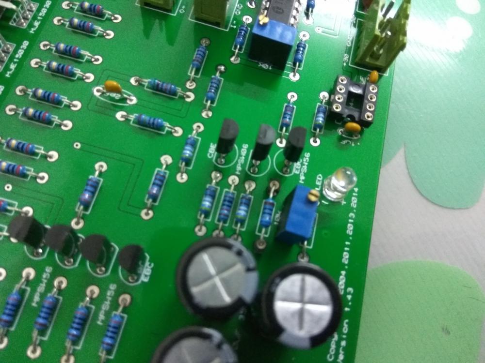
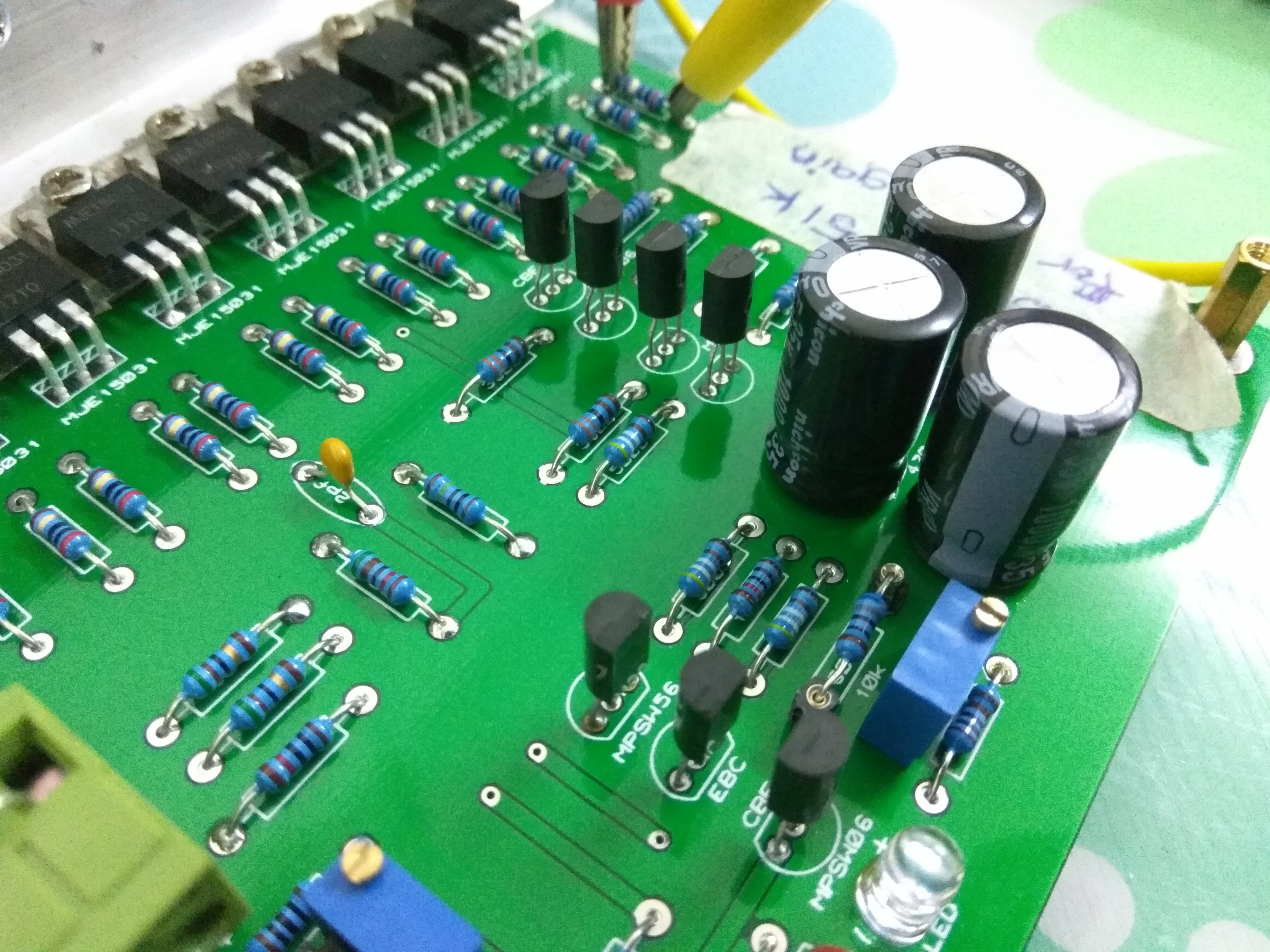
I'll test that when I have the time. Here's a closeup pic. You can see (just barely) there's an insulator and a washer to insulate MJE devices from the L bracket.

For sanity check I've double/triple checked pin orientation with respect to the silkscreen and all components correspond to the silkscreen orientation (had this problem with a NAP200 build where one of the transistors are backwards).
32 minutes ago, jose said:Have you tried to change the THAT340 for other?
I only have 2 units and both boards are exhibiting same behaviour. I tested one of the THAT340 prior to installation, it measures fine and matched within respective P-N channel.
So the MJE are rated up to 150V while the MPSW are rated up to 80V. How likely have I fried the devices on my board? Or is it current that fries them and not voltage?
There's no smoke, no smell. -
11 hours ago, Pars said:
What does V+ and V- look like? Also, with the amp off, set your meter to ohms and check continuity from each output device tab (tab, not the screw) to the heatsink. Also, check from a tab on one of the first 4 devices on the left to the tab of one of the 4 devices on the right side.
V+ and V- look okay, 29.5V and -29.87V.
I've checked continuity when I mount the devices to the L bracket heatsinks. Yes there's mica insulators with plastic washers but I cut down the mica heatsinks to size because they're too wide or else they won't stay flat and stack up. That could be the point of failure there.
I check continuity on the tab after every 4 devices mounted. I didn't check cross continuity between the devices on the right and left however, I checked continuity on random output device against the heatsink because I assumed if one has continuity then all of them will have continuity.
The first 4 devices on the left to the tab of one of the 4 devices on the right side should NOT have any continuity correct?
6 hours ago, jose said:Have you tried to download the BIAS?
I don't understand you.
-
Jeeybus, I'm fucked. I can't lower the O+/gnd O-/gnd 3.3V offset at all.
-
On 11/5/2016 at 8:52 AM, Pars said:
This is a balanced Dynahi? That is one measurement (offset of O+ to O-). First, you should set DC offset for O+ to gnd and O- to gnd. Get these both as close as possible; should be able to get each to within 5mV without the servo. If you can't, get them as close as possible. Then check O+ to O-. Not sure what these boards have for pots on them. By going back and forth, you should be able to get them all pretty close.
EDIT: and have the inputs either grounded or turn the volume pot all the way down.
So I am measuring the offset for my balanced build and the O+/O- has near 0mV offset, but the O+/gnd and O-/gnd has 3.3V offset. Is this correct? Won't this destroy single ended headphones since their ground is tied?
-
The heatsinks are pretty hot with 750mV, plus I'm using a Sigma22 for both boards and their regs are heatsinked to the amp floor panel. The PSU floor is hot too with one board at 750mV so I've lowered it to only 450mV for now.
I haven't tried it out yet as my balanced 10k pot it still in the mail. I was wondering will there be any adverse effects if I use my balanced DAC (Matrix Mini-i) as pre out to the dynahi without the 10k pot? Can't really find the output impedance for the Mini-i XLR at the back, but the headphone out is 12 ohms.
-
Correct, they're red and rated at 1.7V.
Replaced them with 360Ω and now can go to 750mV

-
 2
2
-
-
Oops, I have to echo some of the alternative findings here. The bias goes down instead when I replaced the 500Ω to 680Ω. Got them on sip sockets to change quickly
I'm gonna go out and get some lower resistors now.
-
Thanks that's very helpful.
-
I'm using a 160VA 2x30V, so that means 160÷2÷30=2.67A?
-
How much current will the amp pull in total?
I want to get a proper rated fuse for it and check whether my Schurter IEC inlet is the proper one. I bought this 2A version way back then without checking first.
http://my.element14.com/schurter/3-101-141/iec-inlet-c14-c18-with-filter/dp/2671668 -
3 hours ago, catscratch said:
**snip
It's too bad, we need more quality electrostatics on the market and preferably not very expensive ones, but we don't need con jobs masquerading as legitimate products.
I agree but I'm conflicted; on one hand affordable stats would be great and I might be able to try one. On the other hand there are several hundred volts on either side of my head and a low price might indicate someone somewhere is cutting corners.
I know, its pretty dumb, "Just because it costs more doesn't mean its built better." but what can you do. Impressions matter.
-
Alright for safe measure I've ordered a strip of sip sockets as well as a bunch off different value resistors. I'll try and see if I need to increase or decrease the 500 Ohm resistors and will report back maybe in a few days or so.
-
That sounds peculiar but I can't argue with results. What about R23/R34? Did you need to increase that from 50Ω?
-
2 minutes ago, rumina said:
i used some sip sockets for the 500 ohm resistors near the 10k pot, makes the change easy. the value of the 500 ohm resistor depends on the vf voltage of the leds you are using, i ended up with some 374 ohm resistors vor 620 mv bias (due the relative small case).
I guess it's my fault because I ordered the LEDs off element14 along with the other parts and they were rated at 1.7V Vf. I didn't check and populated the board with the LEDs.
So since you lowered the resistor to 374 ohm, does that mean you can't get a low bias voltage with the stock 500 ohm?
-
Thanks a lot Pars, at least I have a direction about where to poke and prod. I've contacted someone who had built using this board too, hope all is well.
-
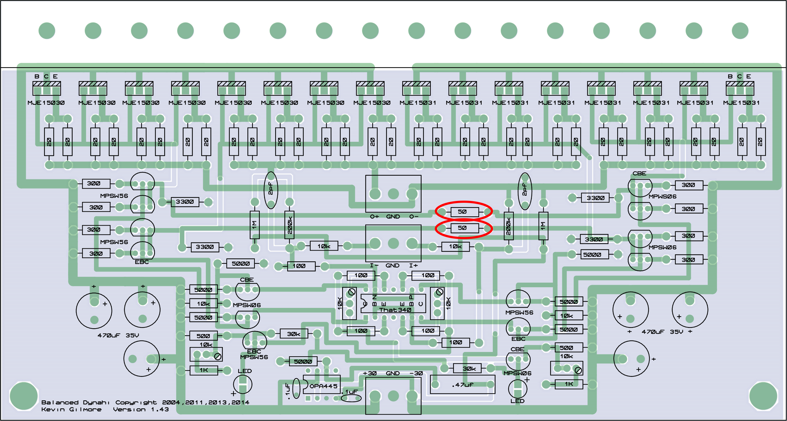
I'm positive R23/R34 are 50 Ohm resistors on my board.
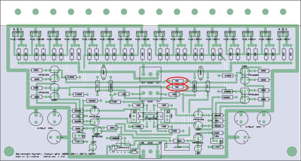
50 Ohm is only 10% of what most people use. Should I increase this to 500 Ohm like other people along with replacing R1/R4 from 500 Ohm to 680 Ohm?
-
6 hours ago, Pars said:
Had to refresh my memory on the original dynalo/dynahi. Yes, you should replace those resistors with the 620/680R to give yourself adjustment range. What do you have in for the bias resistors (R23/R34)? The schematic I have shows 100R, but I think most use 500R?
5 hours ago, jose said:Yes, you can change r500 (next to Trimpot) for other from 620 Ohm to 1K.
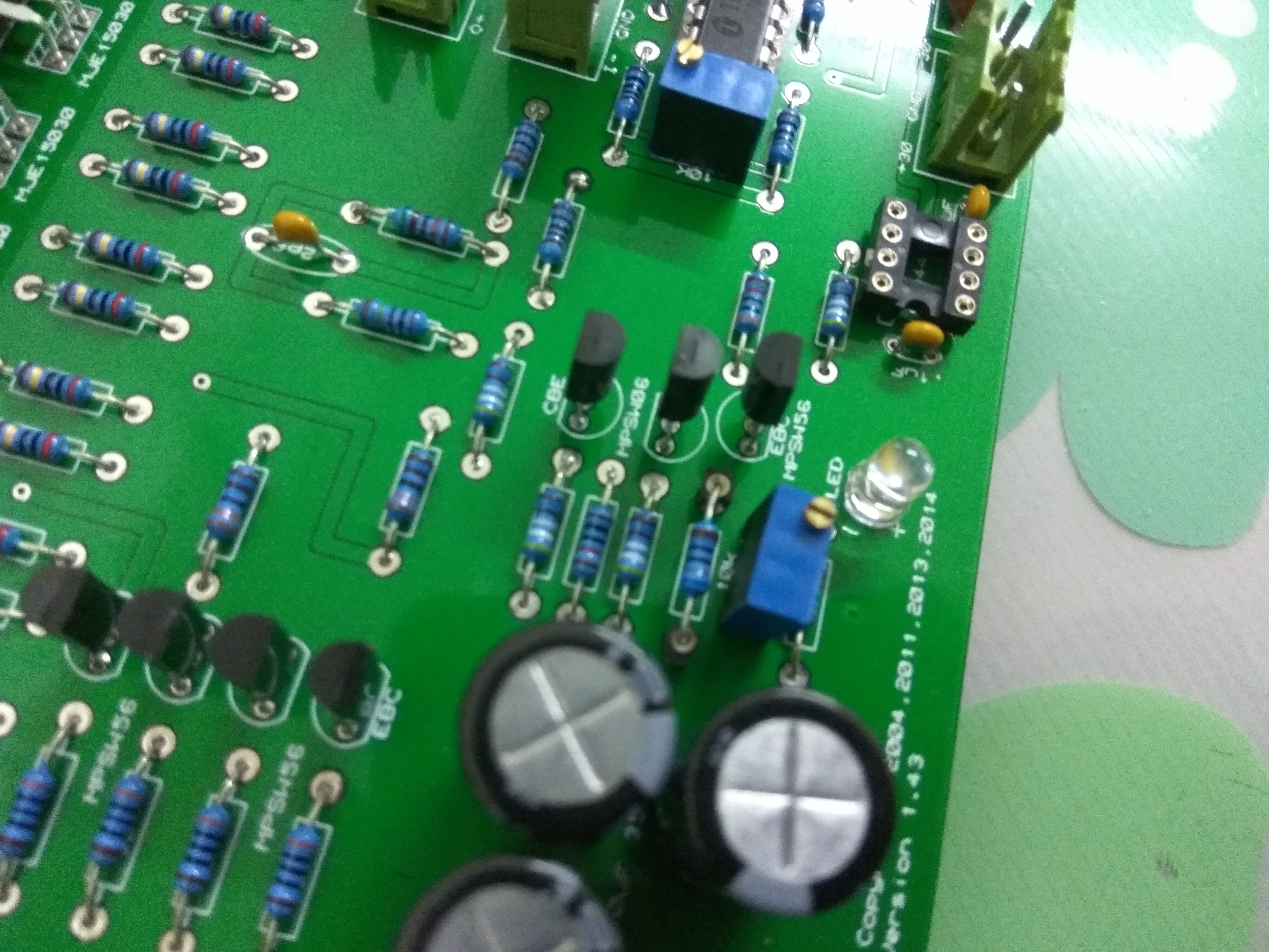
Thank you both so much. @Pars are the R23/34 the resistors next to the trimpots? If so I have them at 500 Ohm according to the board. I have the board with this layout, which is the dynahibal9.zip in the staxpcbs Google Drive folder.
Regarding my other points in my previous posts, why did the output offset suddenly shot up to 5V? That amount was insane.
I've carefully set the trimmers flanking the THAT340 in their mid point with my DMM before soldering them in and haven't touched them yet. The moment the offset shot up I switched it off and scrutinised all solder and tried smelling all devices but nothing looked or smelt burnt.
I turned the lower left/right trimmers all the way down again and turned it back on, and the offset was only 1mV. Then I tried biasing them back up to 270mV and the bias stayed low. I switched it off, and then after a few minutes switched it on again and the offset shot back up to around 3-4V and drifted down to several hundred mV. I repeated this with min 140mV bias, switching off/on, working all the way up to 200mV where the offset stayed low without displaying the erratic behaviour.
Both L/R trimmers are turned up in half turn increments at the same time while watching both the bias voltage and offset voltage.
Inserting OPA445 makes the offset drift more than without. Probably because my devices are matched well?
-
Shit. at 270mV bias the offset was less than 5mV suddenly shot up to 8.5VSo after lowering back both trimmers the offset went back down below 50mV. What could this be caused from? My Hfe measurements are
MPSW56 = 201 for one board and 256 for another
MPSW06 = 293 for both boards (bought on tape reels so they're pretty uniform)I found out when I increase the bias the offset stays low. Then if I turn it off, and then turn it on again the offset shoots up to several volts.
***edit
This post by amb suggests to change the 500Ω resistors with something higher like 620Ω or 680Ωso I'm going to try that in a bit.
https://www.head-fi.org/threads/dynahi-dc-offset-adjustment.165788/#post-19607042. Now biasing at 200mV, before putting in OPA445 offset is 1mV. After inserting OPA445 the offset jumps up to several hundred mV on startup, drifts within a few dozen mV, and settles down now at 10-14mV. Now it is dropping again to 7mV, I presume after the parts have started heating up to their operating temperature. Is this normal? With the OPA445 off, the offset does not jump upon startup but drifts around 20mV, goes down to 10-15mV, and starts settling down at 1-3mV
-
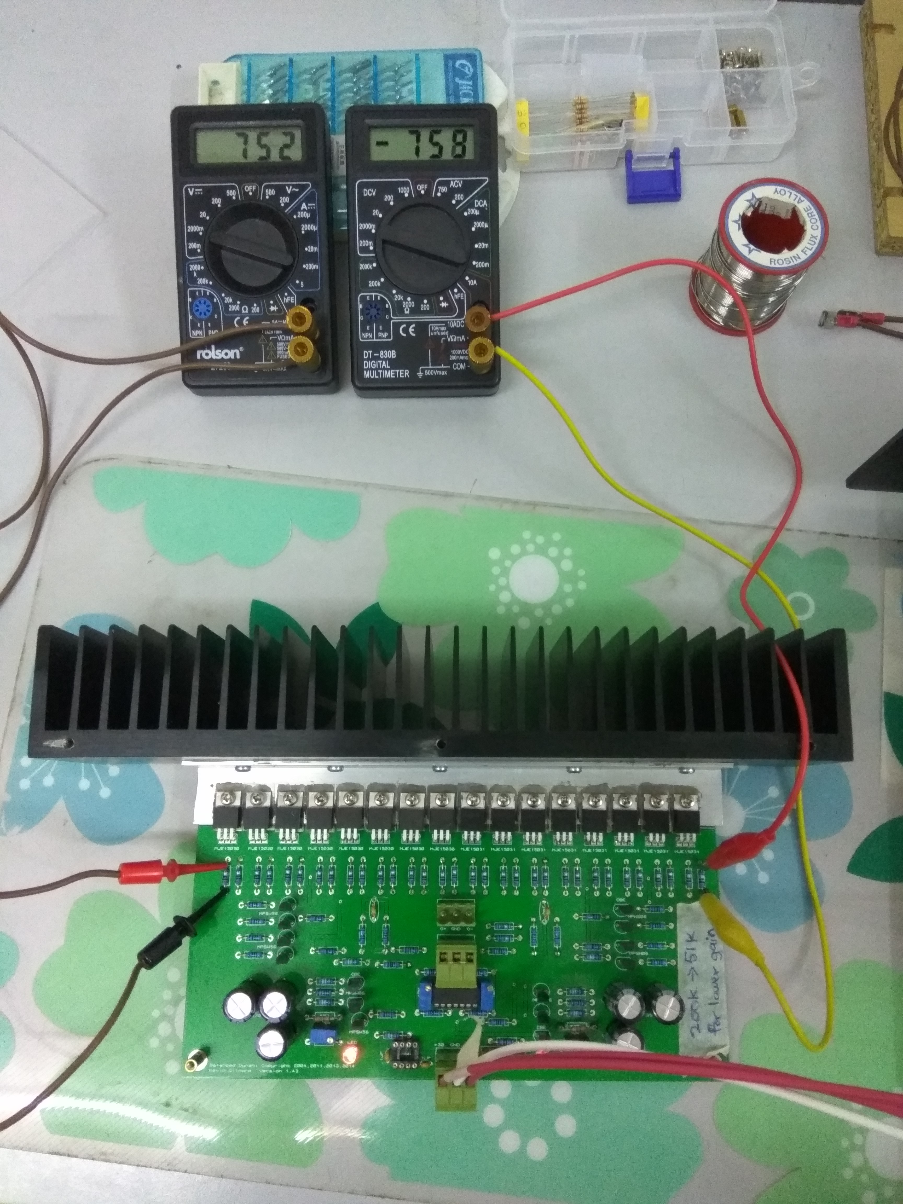
I'm having some problems with biasing my board. I can't get it to bias higher than 320mV± on both rails. At first I had a light bulb limiter and thought it might be lowering the bias but after removing it it's still the same.
I'm using 51k for the feedback resistors. Could it be the reason why?
The image is showing around 484+-mV but I cannot get a low offset with it and 270mV is the highest I can get with low output offset.
-
-
10 hours ago, Whitigir said:
Wow, taobao is a dangerous place if they use other builder pictures for advertisement on building KG T2. Who knows what they build it out to be....I hope it won’t bring KG T2 any negatives, or somebody need to pull some strings
I doubt people will base a proper product with the China fake counterpart. From Taobao especially.
Though I do have a friend who keeps buying Aliexpress opamps and raving how good they sound compared to the stock opamp in his class D amp. Only time I go to Taobao is for their chassis, can easily cost less than half or a third of eBay prices.
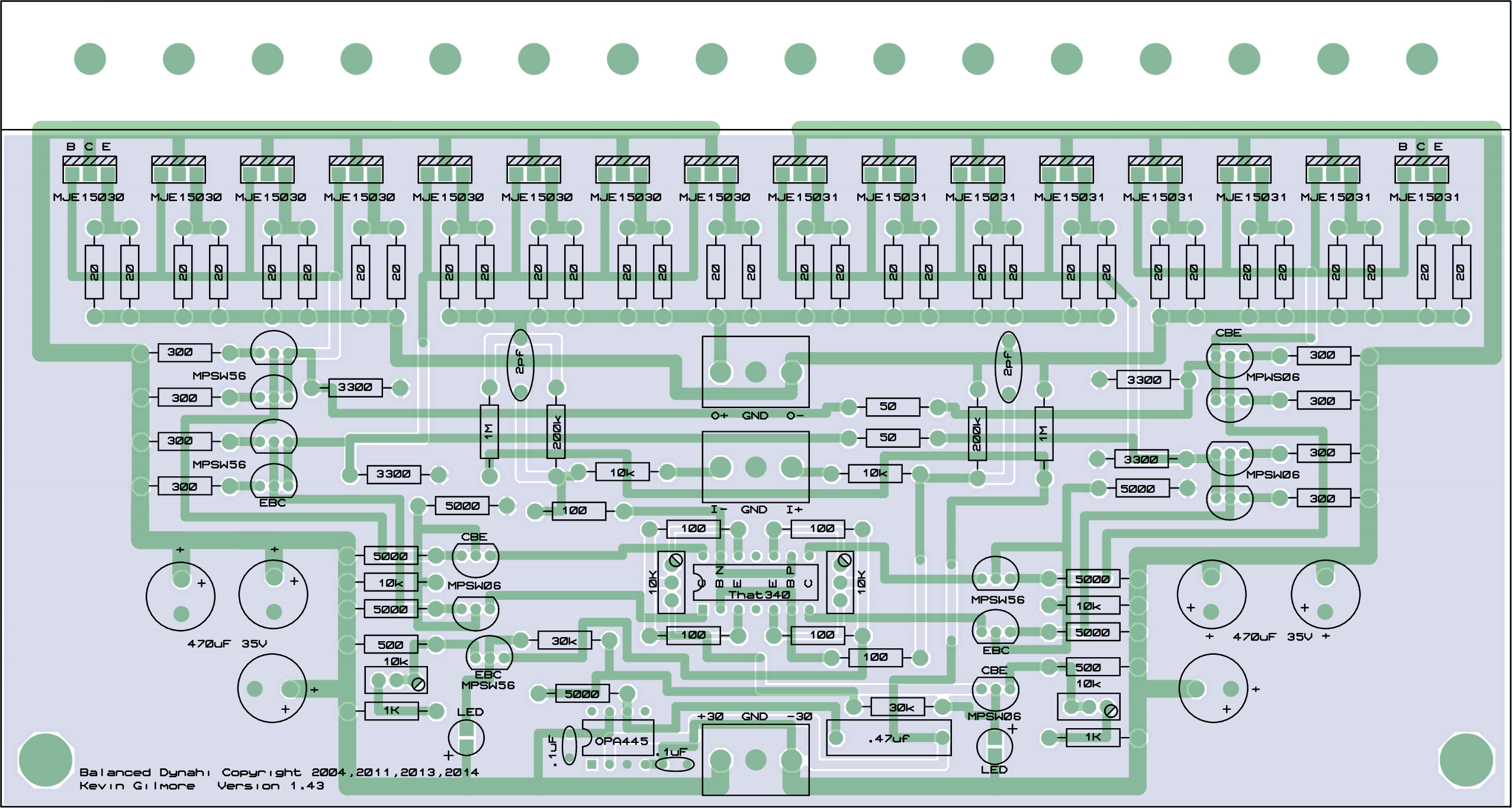


KG Balanced Dynahi build discussion thread
in Do It Yourself
Posted
What I did was I turned up the two pots beside the 500R together without looking at the offset properly. So it just kept going up while I was trying to focus counting to match both pots' rotation. To correct the offset I had to turn the other one less or more and that fixed the offset right up.
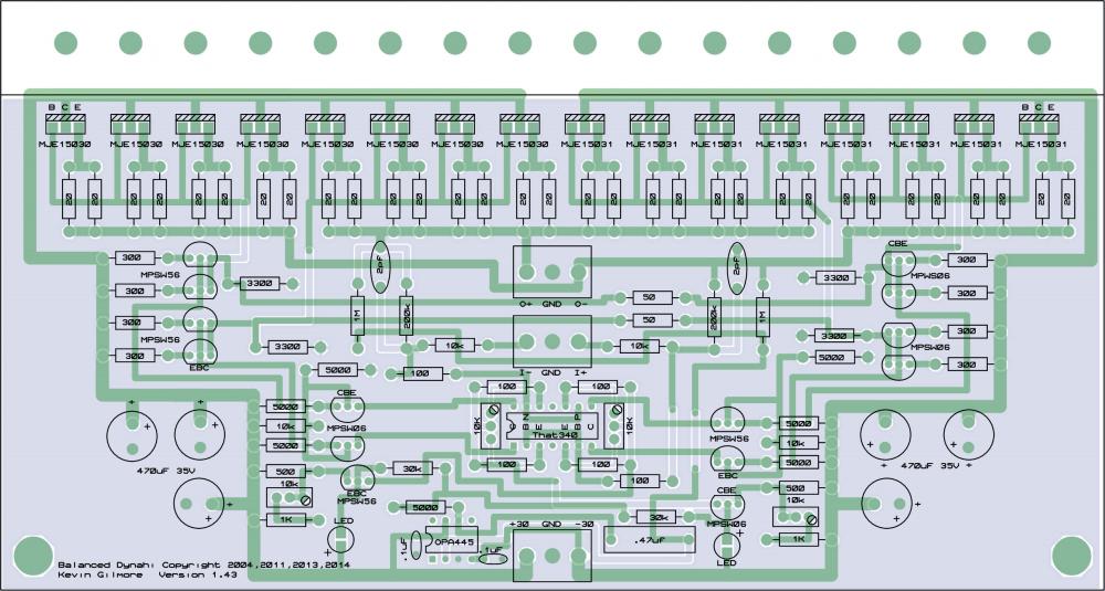
Resistors are different now; 50R are now 100R and 500R now are 680R.