penmarker
-
Posts
138 -
Joined
-
Last visited
1 Follower

penmarker's Achievements
Limited Edition Bronze Participant (4/6)
19
Reputation
-

unbalanced/balanced to balanced tube input
penmarker replied to kevin gilmore's topic in Do It Yourself
Ha, the mica insulation for the 100V section made me nervous. Its great that I shouldn't worry about it. -
unbalanced/balanced to balanced tube input
penmarker replied to kevin gilmore's topic in Do It Yourself
On a scale of 1-10, how ok is it to use mica insulators instead of ceramic for the HV section? -
This thing is comparable to one of those OBD throttle controller that you plug into your car so you'll only need to press half the pedal to get full throttle and tell your friends you got 20+hp.
-
goldenreference low voltage power supply
penmarker replied to kevin gilmore's topic in Do It Yourself
Sounds all good then. My GRLV runs probably around 40-45°C but the case for PSU only has vents at the top panel and no bottom panel holes (hard to convect heat if there's no air inlet at the bottom). It's not as hot as Dynahi heatsinks. -
goldenreference low voltage power supply
penmarker replied to kevin gilmore's topic in Do It Yourself
What's the normal temperature for the transformer and PSU of a pair of GRLV powering Dynahi? -
I've replaced all MPSW56/06 with matched using circuit from here. I've also replaced my LEDs with matched LEDs. Previously the LEDs were correct at 1.7Vf but they were rated 20mA while the new ones are only 2mA. The amp still has that intermittent rustling noise when warming up but volume was quite low. I've also realised the high pitched turn off sound is not normal after reading back like this guy. Since I'm not in a rush I spent a few days tinkering with the biasing and offset. With lower offsets between -O/+O to ground, there's no turn off high pitched noise on se output. With lower offset between -O and +O, there's no turn off high pitched noise on bal output. Lower offsets during turn on mitigates turn on thumps but it will affect readings when the amp has warmed up to temp (also the high pitched turn off noise returns on either se or bal out). All 4 VR pots on the board will affect every reading that needs to be checked. Finally settled with a setting that has soft turn on thump, no high pitched turn off noise, lowest rustling warm up noise on my very sensitive Final Audio Pandora Hope VI with 16ohm impedance and 105dB sensitivity. On HD650 and HD525 there's no noise floor. My throwaway portable Oneodio Pro-50 has a medium noise floor and very low warm up noise. The only downside about this is the +ve and -ve biasing voltages are different 750mV and -740mV. Being only 1.33% difference, I don't think I'm too worried. All in all such a great project. Maybe my next Dynahi SuSy I'll just use MPSA and see how it runs.

-
The ground for SE output goes to one of the output ground. All the grounds on the board are on the same plane. For SE in you'll need to tie the L- and R- to their respective grounds.
-
Thanks. I’m currently using MPSW parts from eBay. My assumption is they’re genuine but it’s been years ago so I can’t check anymore. Bought as a lot for 06 and another lot for 56. I matched them by HFE with a diy transistor tester.
-
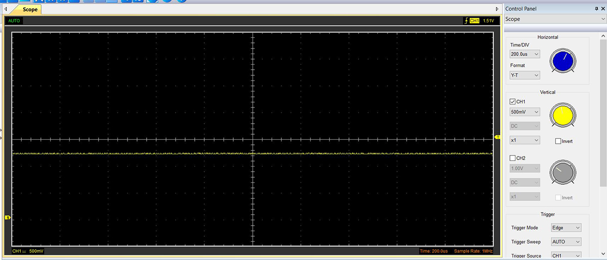
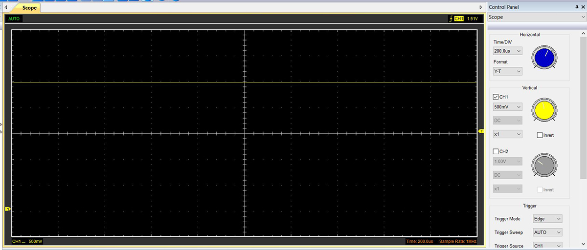
After replacing the input devices with K170/J74 I'm still hearing noise from the single ended out (with sensitive headphones). It sounds sort of like a frying sound that comes and goes. I probed the amp with my USB scope. The signal from FET devices and the first transistor is very clean (Q4, Q5). I found the noise came from the transistor pairs before the power transistors. Not sure what causes this. Is it because they're not closely matched? Is it dirty power?
-
Yup, I'm using Mill Max sockets for the THAT340 so swapping them out was quick. I was thinking about coupling them together so each pairs will be same temperature. Left it on for a while and touched the jfets but it seems they stayed cool. Is their current draw way lower than what we would find in speaker amps?
-
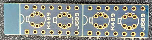
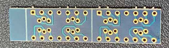
Just found these k849/j689 adapter boards with incompatible traces from last time's group buy. I could probably adjust these instead to make them pin compatible with back to back J74/k170
-
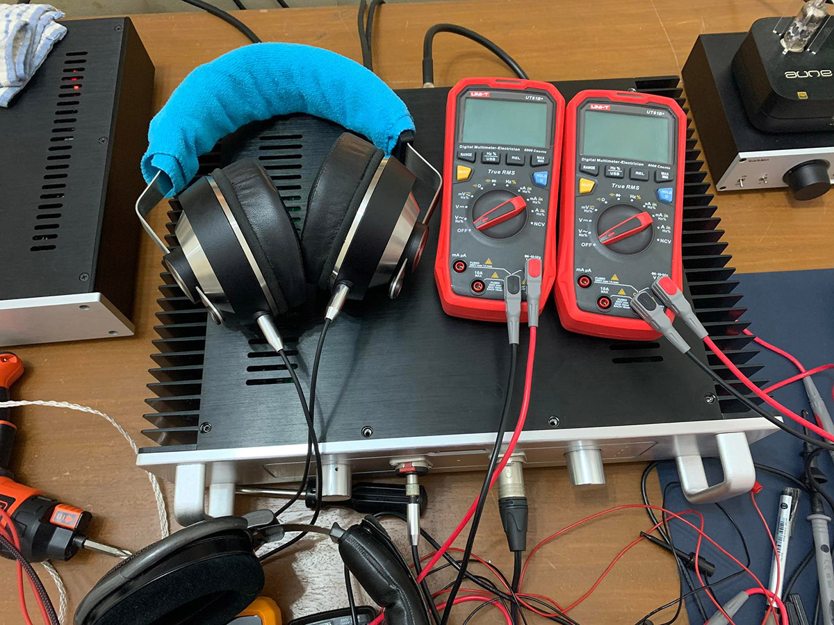
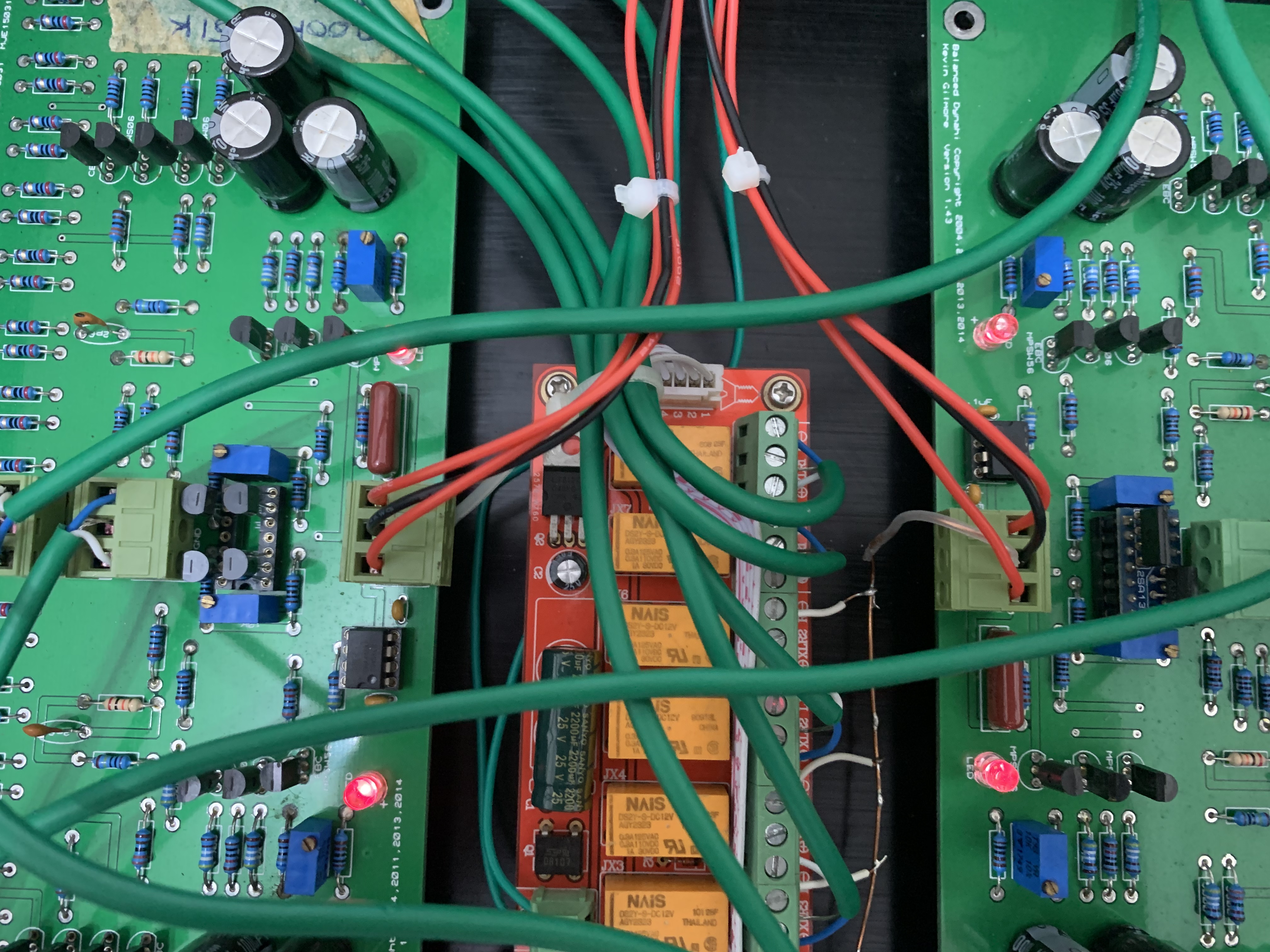
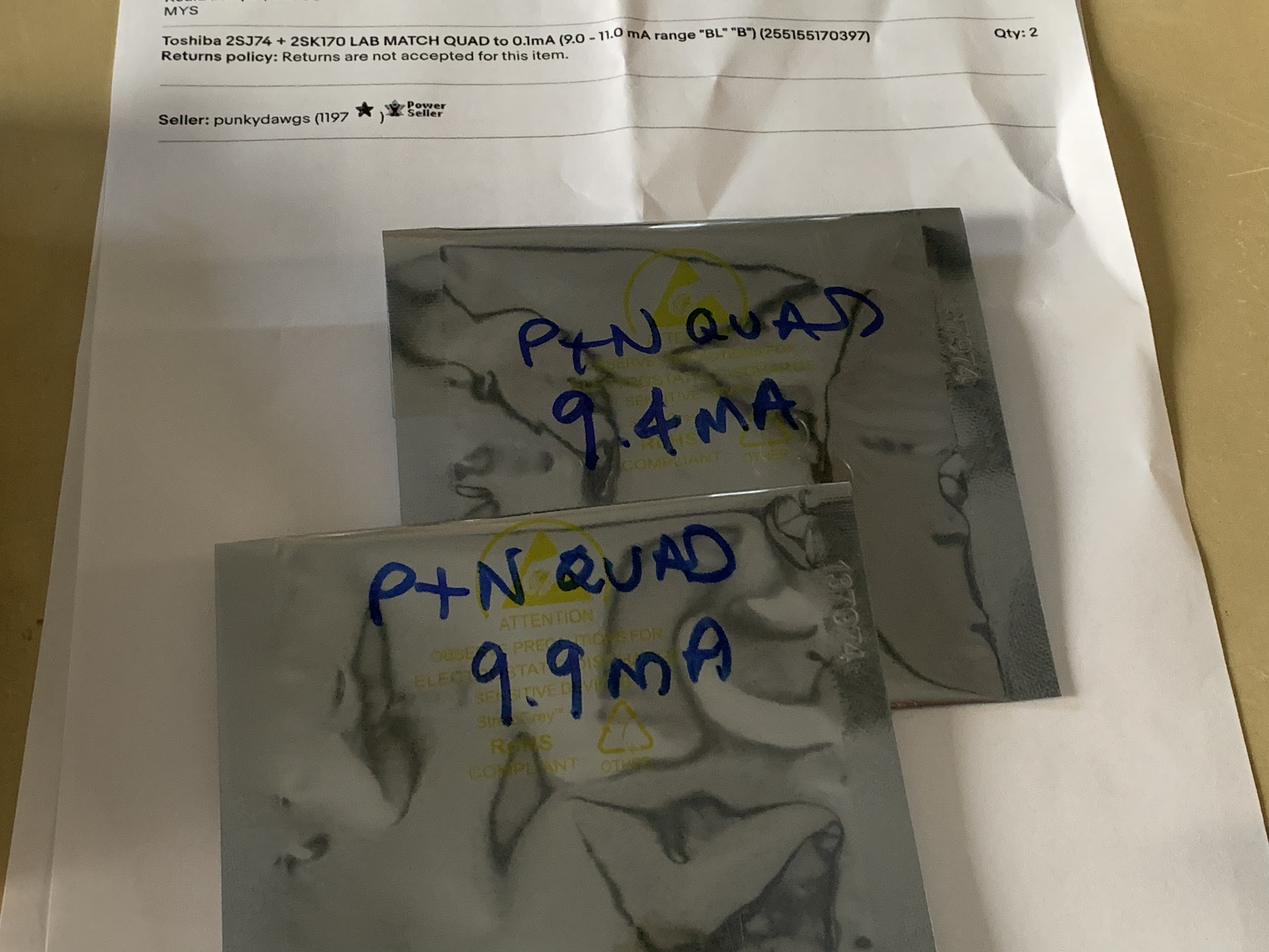
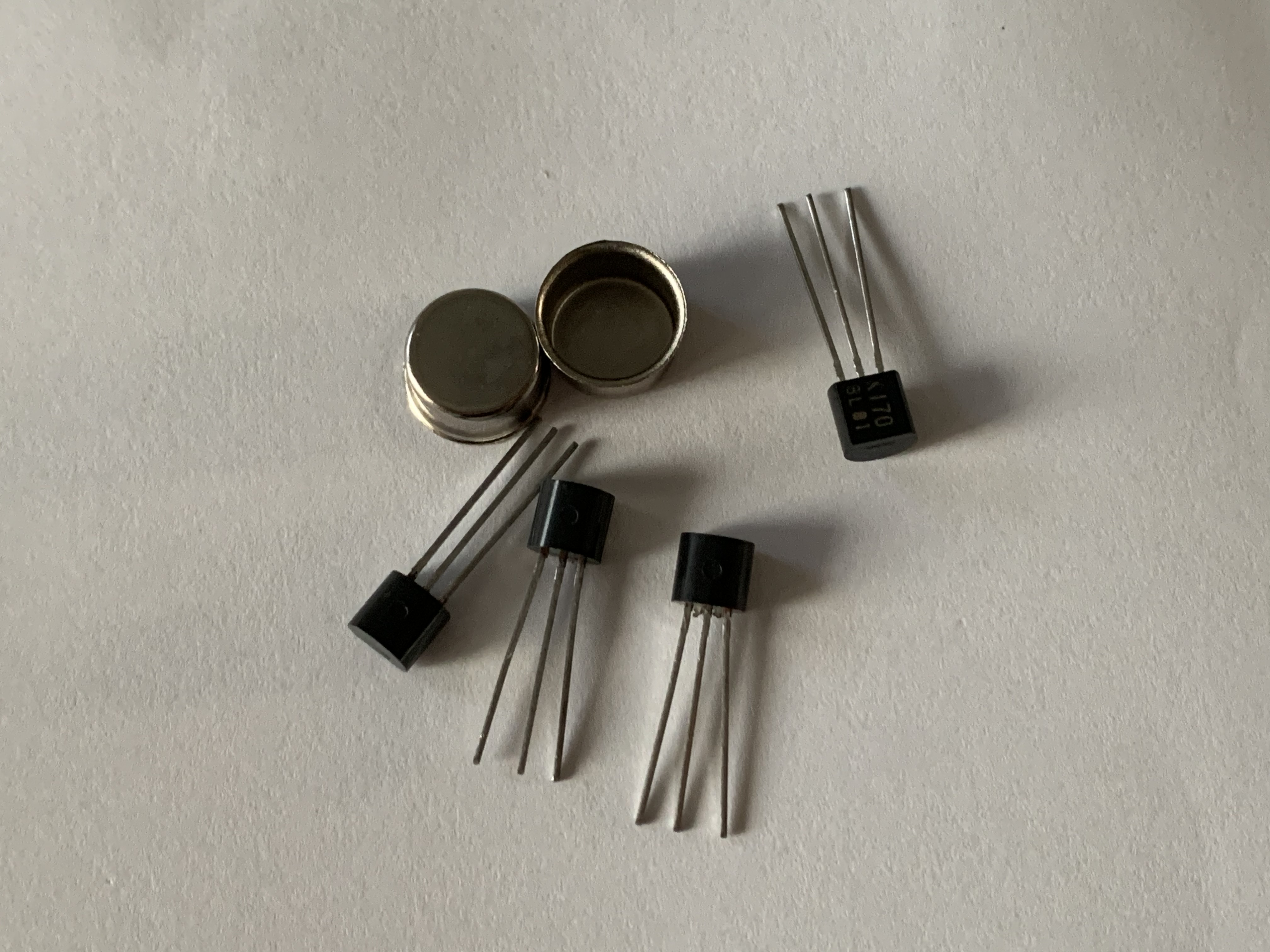
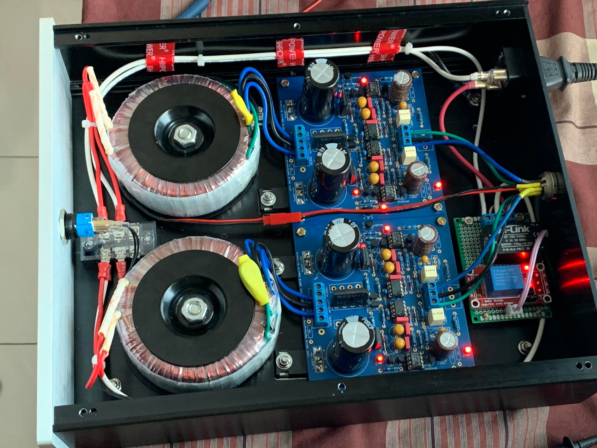
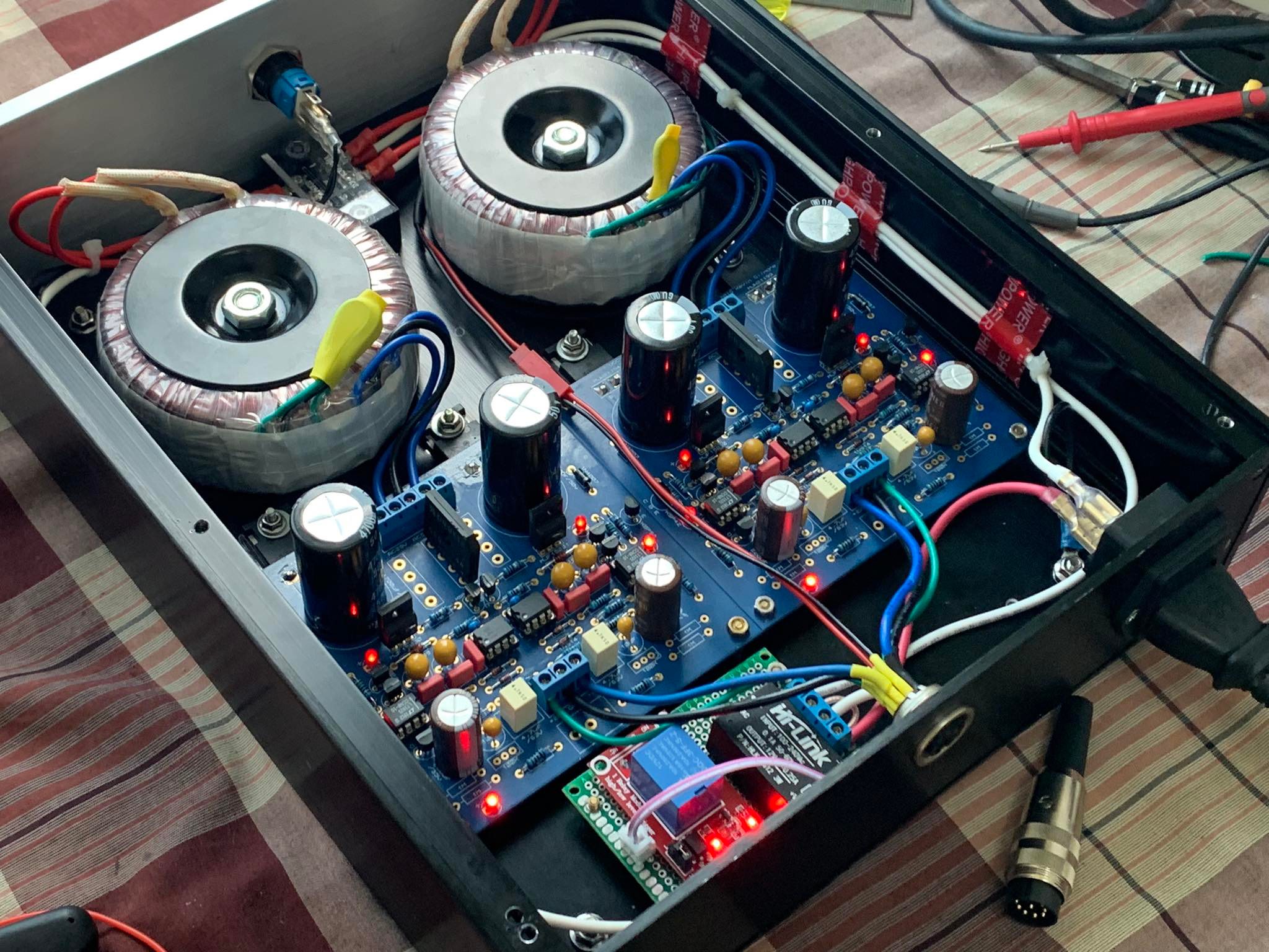
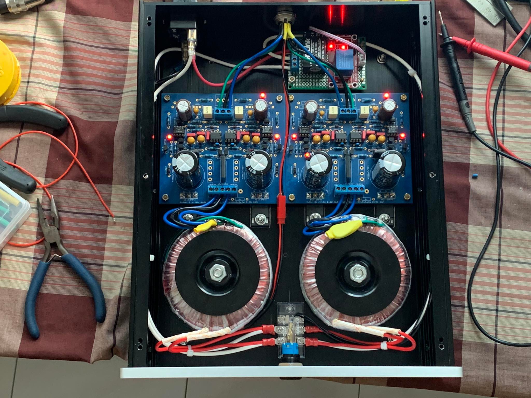
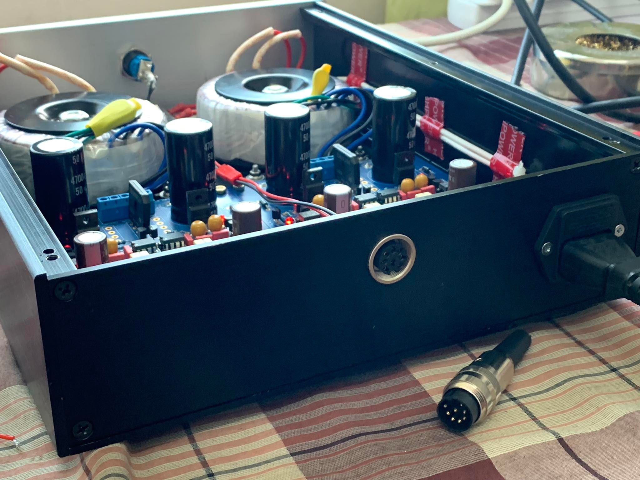
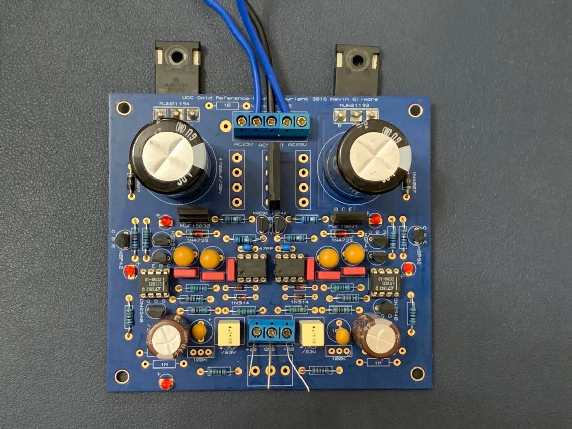
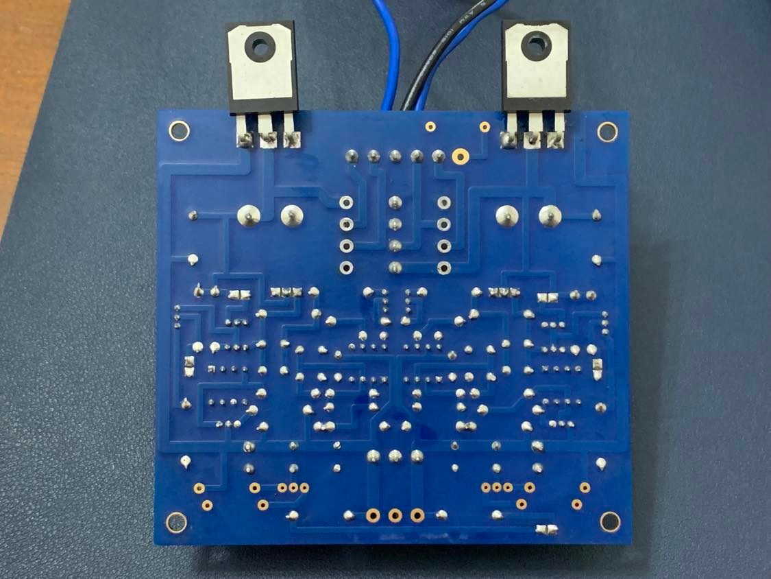
Received my j74/k170 from punkydawgs the other day. He even included some metal cans to thermocouple the packages. Installed in my Dynahi today (left channel shown) and did some bias checks. All look good. The difference between left and right is just a bit perceptible I’ll fabricate some adapter board with protoboard if feasible so I can heatshrink the packages back to back. If can’t I’ll just use the included metal cans with some thermal paste.
-
goldenreference low voltage power supply
penmarker replied to kevin gilmore's topic in Do It Yourself
Glad I got the Lumberg SV80 and KFV80 connectors. Smooth like butter and low profile. 329587661_5880443992073835_6229699499347506353_n.mp4
-
goldenreference low voltage power supply
penmarker replied to kevin gilmore's topic in Do It Yourself
***Edit 2: Seems that the BR was faulty, it works fine now. Can someone suggest me where I can start troubleshooting? I have a GRLV set for 30V that worked previously with a dual transformer. I got myself a center tapped transformer and adjusted the bridge rectifier accordingly - only one in the middle. Wiring in is correct for a center tap. The GRLV blows a 1A fast blow fuse every time turned one. Left side +30V has time to reach +30V before the fuse trips while the right side -30V will not light up in time. Transformer is 100VA 30V - 0 - 30V The bridge rectifier is reused from the same board **Edit Here are my findings If I connect only the center and right terminals, the whole board works fine. + and - 30V on the outputs If I connect only the center and left terminals, the board reads wrong and the bridge rectifier heats up. I think the BR is toast from desoldering. I'll try taking it out and testing
-
We can weaponise it and make people think god is speaking directly to them.