navigator
Members
-
Joined
-
Last visited
Everything posted by navigator
-
..hmmmm... Interesting. It is really this problematic. I thought there are just replacements what I can order from big ones like RS, but I realize it is far more complex and now I understand why we can buy these pairs on ebay. :-( Thanks for your help!
-
Hi, I just about to finish a Dynalo Mini and strugglig with the input fets. I did read a lot back this thread and I see what is obsolete etc., but I can not find what I can order. I know on ebay there are unknown sellers selling these, but if you guys have a suggestion I can get from Mouser / Farnell / similar, that would be great. I've looked these so far: 2SC3381 2SA1349 2SK389 2SJ109 LSK489 LSJ689 2SK170 2SJ74 Thanks a lot!!
-
jose, Pars, I appreciate your posts. It is important for me because my first impression from reading the threads was that CFP is clearly above, now, I see the picture is not that simple (as always :-). One more thing, jose, what headphone you use? Thanks!
-
I'm reading backwards and from the 50 page I'm at page 30, not bad I think :-) , but I continue I also admit I'm not very good in understanding transistor circuits, even I built a lot, but I thought grounding the negative input will virtually ground the negative output and that is not what I was looking for. If that is not the case, the positive signal is inverted and gets into the negative input, that is great. I see the feedback is crossed, so the positive output gets fed back to the negative input and same on the other side, but to fully understand how that works is above me. The best schematic I found so far are the SSDynalo-v1-5-PS.jpg, SSDynalo-v1-5-Channel.jpg, SSDynalo-v1-5-Amp.jpg in pictures. Do you know a pdf version? Thanks, I started from the back because at the front the schematic links do not work. I know why, but I thought I should find in the recent posts. In general I was familiar with the Dynalo, but now I read the beginning also and see posts saying it is symmetric or assymetric in and symmetric out. I guess than it means there is signal out on the negative output, not virtual ground. Thanks,
-
Hello, What are you guys using to feed it with assymetric input signal, to get output symmetric? I am searching for the most up to date schematic, but as I see from assimetric signal it will run only one half and assymetric output. There is no phase invert or such to feed the negative inputs. Do you maybe has experience with this and some interstage transformers? Thanks!
-
Hello, I would have still the same question. I was reading the thread and I found a few bits of evaluations, but I would also appreciate if you guys would comment on how it really compares with ss dynalo. What are the positive and negative aspects with what source, what music and what headphone? How is it pairs with typical sennheisers "treble rich" sound? Is it emphasize it or compensate it? Neutral? Thanks!
-
Reading the other threads in the last weeks, may I still add a Dynalo Mini + TKD pot? I did not touched the chart, may I add it? Thanks!
-
I have updated the GRLV and the CFP2 BOM, based on the layout, if you guys have any interest to that. I can not upload it, I can not attach here either, out of quota :-( https://mega.nz/#!8kYl3YoQ!3t851N3SOzj_pxxcOZtUznVPTXJw4jBhG7tySlaWgUI https://mega.nz/#!B4YhmBRD!Zk4EP4vQCHMur2VUzOVsliOkhzwgmH7TpERhRc5fDB4 It is important to mention that I did not built yet these, I have used the assumptions as I described before at the amp, at the psu it was pretty straight forward, there are only an an antiparallel diodes on the opamp input and some small caps on the output and some at the opamp power rails what was missing from the schematics.
-
Hi All, I'm sorry for the long text, but it might be interesting for you. I have reconciled the schematics <> BOM <> layout and found the following differences: Q27, Q28 are BC556, BC546 at schematic, but PZTA56, PZTA06 on layout and BOM. I guess just for the SM packaging. Q22, Q23 are BC556B ? and Q24, Q25 are BC546B ? These are missing from the BOM. Since layout says PNP=BC556B, NPN=BC546B, I guess yes, it is the same type. Trimmer is RV1 on the schematics, TR1 in the BOM. It is just a minor designator change I guess. C2 is 100uF on the schematics, 47u in the BOM. I guess value is changed. C5 is 4uF on the schematics, 100uF in the BOM. As I see C5 designator is changed, I see 4u7 in the DC servo loop and C5, C6 just added to the power rails. R23 is missing from the BOM and layout. I guess it is cancelled. 2 x 100nF (on +- power of the opamp to ground), 1x 100nF parallel (?), 1x 22pF missing from the schematics, no designator in the BOM. I guess those are added later, but the two 100nF close and parallel is interesting. U4 on schematics is IC1 in the BOM. No other IC so it is surely just a designator change. R10 is 50k on schematics, 10 ohm in the BOM. R9 is 10 ohm on schematics, does not exist in the BOM. R9 vs. I guess R10 is a mistake in the BOM. Should be R9. R12 is 200ohm on the schematics, but 2 x 110 ohm on the layout and in the BOM. I guess it is just rearranged. R17 10k on schematics and BOM (but a 20k is inserted also with no designator), 20k on the layout. I guess that is changed to 20k. There is a 1k on the layout, series with the input, missing from both schematics and layout. I guess it is added later. Is it added always or only in case of oscillation problems? R14 and R32 are both 34k on schematics, instead R14 built as 68k on layout and in the BOM. R8 is missing from the BOM. R16, R29 is missing from the BOM. The diodes are missing from the BOM. I guess all 1N4148 now. Are you guys sure there is not a more recent schematics than the cfa2cmirror.pdf? I have updated the BOM, but would need confirmations on the above before this update can be valid. Thanks a lot!
-
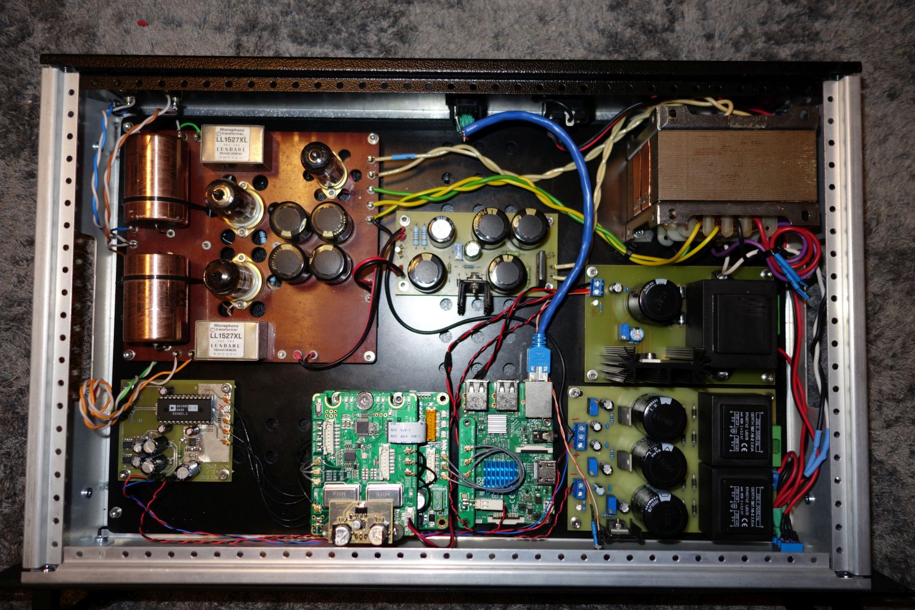
A DAC, including an RPI as player. Input is ethernet. DAC chip is my favorite, AD1865. From the RPI it fed through an I2S buffer and reclock, than an I2S to PCM converter. That is not my design. The DAC board is my design, at the end, there is no low pass filter, the interstage transformer acts like that. Than, the triode amp and buffer circuit is designed by a friend, I built it on cnc milled plate and point to point wiring. Several modifications made, first I did not like it. It was too dry and sterile. That time the end stage was based on ECC83s. It is redesigned and made with 5687s. Now, it is pretty good. Once I "finish", I will design and get cut and bent a copper case. But now, I'm in a stage that I need a decent headphone amp, tho be able to listen to music when the kids are sleeping in the other room.

-
Thank You! So, for layout drawing, I can create from the gerbers. As I see the GRLV is the goldenreference6d.zip, the CFA2 is the cfp2hmt.zip linked earlier here. I did read through the "And now for something completely different" thread, but the base doc links are pointing to http://gilmore.chem.northwestern.edu/*** I thought the cfa2cmirror.pdf is used for simulation of the CFA 2. Is that accurate to create the BOM based on that? Is that the schematic used to create the layout? On the schematic of the GRLV, I assume it is the latest : goldenreferenceboard.pdf, can I use that to create the BOM and start ordering components? Thanks a lot!
-
Thank You for the group buy! I'm excited to try the GRLV + CFA 2. May I ask someone links the GRLV and the CFA 2 build docs, like schematics and layout, which transistors should be matched etc? I did found some jpg schematic, but not 100% sure it is the version on the GB. The links from Kevin does not work for me for a few days now. Also, how do you guys match transistors? With a simple low current beta meter or you make a simple circuit and simulate the current in the application? Thanks a lot!
-
Noise is just one parameter. Internal resistance, reaction time etc. is another - which is less important with class A amp, but still, I do not think that only noise counts. ... and, it is not straight forward that a better measured would sound better. I'm almost sure I will stay with the GRLV, but I'm still curious. Long time ago, with preamps I did like the battery supply. That was NiCd.
-
Hi All, What do you think on running this amp on 4 SLA battery? I know, not very practical, need decent batteries for hours of listening. I'm really excited to build CFA 2 and supplied from GRLV, but I'm just thinking about battery also. Probably I would not stay with batteries, but I'm curious if you have tested. ? Before, I had more effect from one PSU to another sometime than one amp to another. I have used to start the amps and do initial tests with a HP6624 PSU and strange, but I was never able to build one as good as this monster rack PSU. .... but, not listened to the GRLV .... yet. Thanks!