


jamesmking
-
Posts
408 -
Joined
-
Last visited
-
Days Won
1
Content Type
Profiles
Forums
Events
Posts posted by jamesmking
-
-
7 hours ago, JoaMat said:
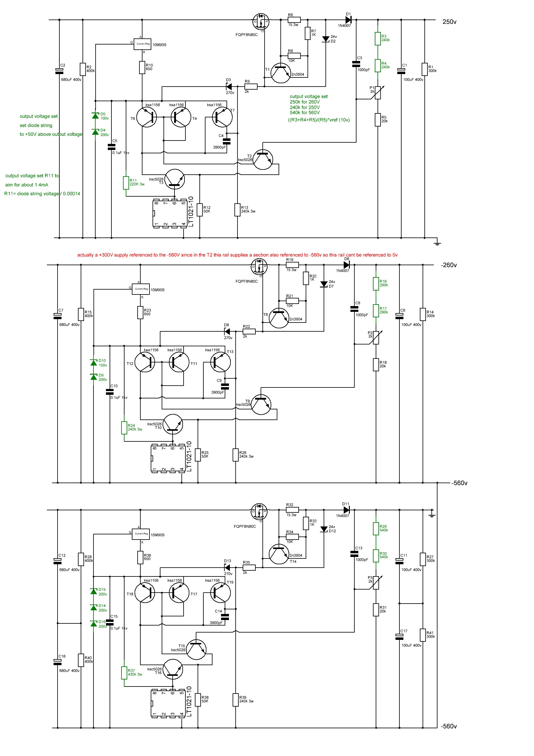
R11 determines the current through LT1021-10 which needs 1.1 mA at 25 degree C. Choose R11 value accordingly.
For +/-500V sections; R11 = 400K gives 1.4mA and 0.8W.
The original published gerbers has All the rails running at around 1.8mA through the R11 resistor except the +-500V rails at almost 2.3mA! The original published gerbers has:
+250V rail (300V zenner string) using 160K so 1.875mA, 0.56W
-260V rail (actually a +300V supply (with 350V zenner string) ) using 200K so 1.75mA, 0.61W
-560V rail (600V zenner string) using 330K at 1.82mA, 1,09W
+-500V rails (550V zenner string) using 240K almost double the required current at 2.29mA... and around 90C+ temperature with the lid off dissipating 1.26W...
so if we set a target of around 1.4mA to provide a little headroom and go for values in the vishay PR03 resistor range available at mouser or radio spares:
+250V rail 220K (available mouser and radio spares) for 1.36mA 0.41W
-260V rail 240K (available mouser) for 1.46mA 0.51W or 270K (available radio spares) for 1.3mA 0.45W
-560V rail 430K (available mouser) for 1.395mA 0.84W or 470K (available radio spares) for 1.28mA 0.77W
+-500V rails 390K (available mouser and radio spares) for 1.41mA 0.78W... that's half a watt reduction in dissipation 🙂 compared to the original published gerbers.
These lower dissipations might even allow the use of Vishay PR02 2W resistors instead of the 3W... time to update the gerbers and schematic again. I will update my gerbers and schematic post.
-
 1
1
-
-
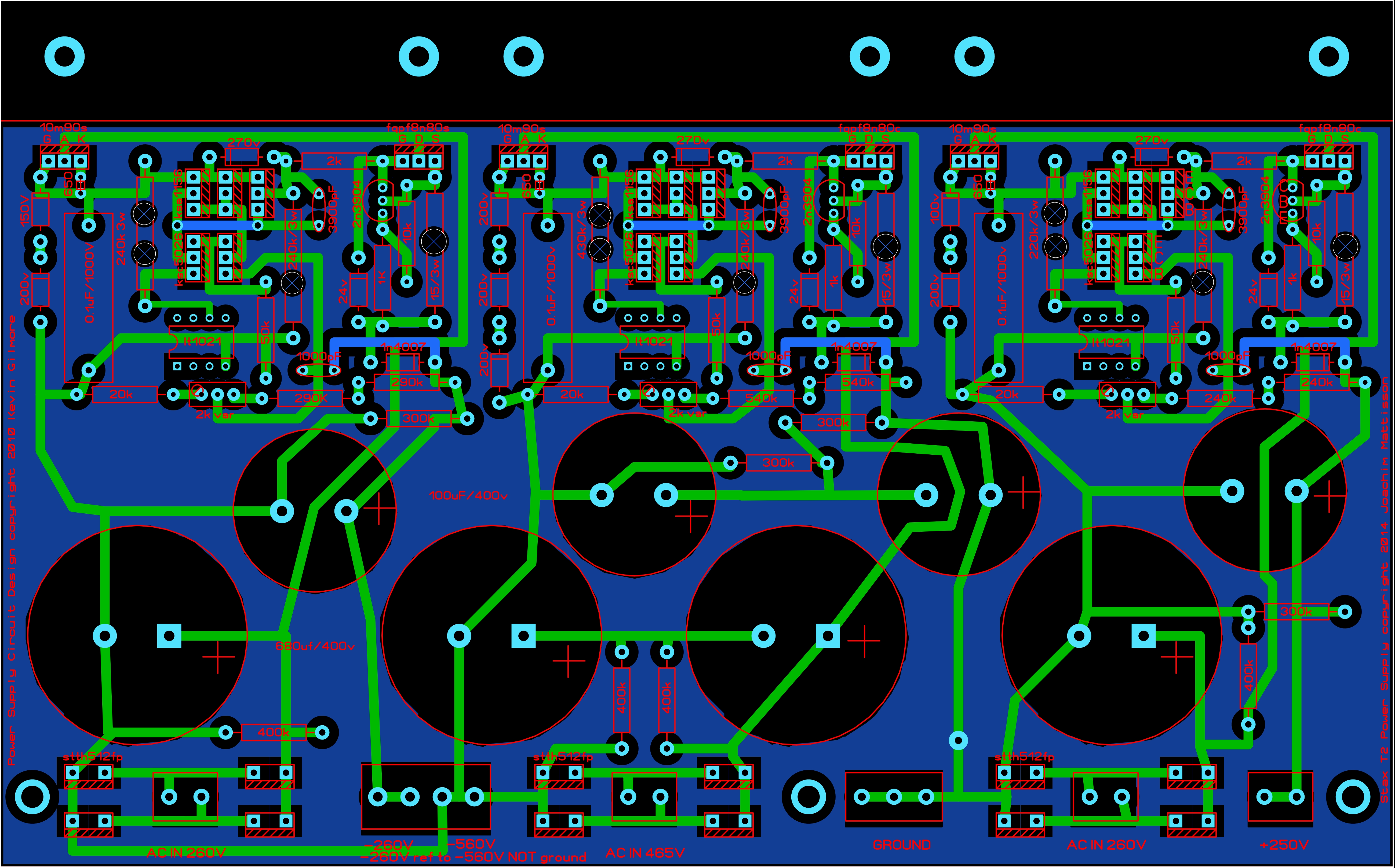
Here the latest T2 psus, I have modified the layout to provide more space around the rather hot R11 3W resistor and added vent holes to the pcb. The pcbs, transformers etc still fit inside a 400mm deep case without issue.
I noticed that the R11 equivalent resistor on the + and - 500V rails runs considerably hotter than the equivalent resistor on the other rails (which also run quite hot).... doing some quick maths, R11 is approximately 1000ohms * the value of the zener serial train /1.818 on all the psus rails except for the +and -500V... Using this formula gives 300Kohms for the + and - 500V rails but in the original gerbers I worked from only have 240K there. This results in higher current flow through the resistor and more power dissipation and hence the higher temperature.
EDIT: thank you Joamat for suggesting the current through R11 should be 1.1mA or more. The R11 values here on all rails are based around 1.4mA with values available in the PR03 Vishay range or 3W resistors. Resulting in lower power dissipation on all rails and especially the +-500V
The gerbers with the vents have been used to make functioning psus and can be considered tested.
This pcb is 220mm wide by 137mm deep and contains the -260V, -560V and +250V rails

t2 kgsshv 250v -260v -560v corrected.zip
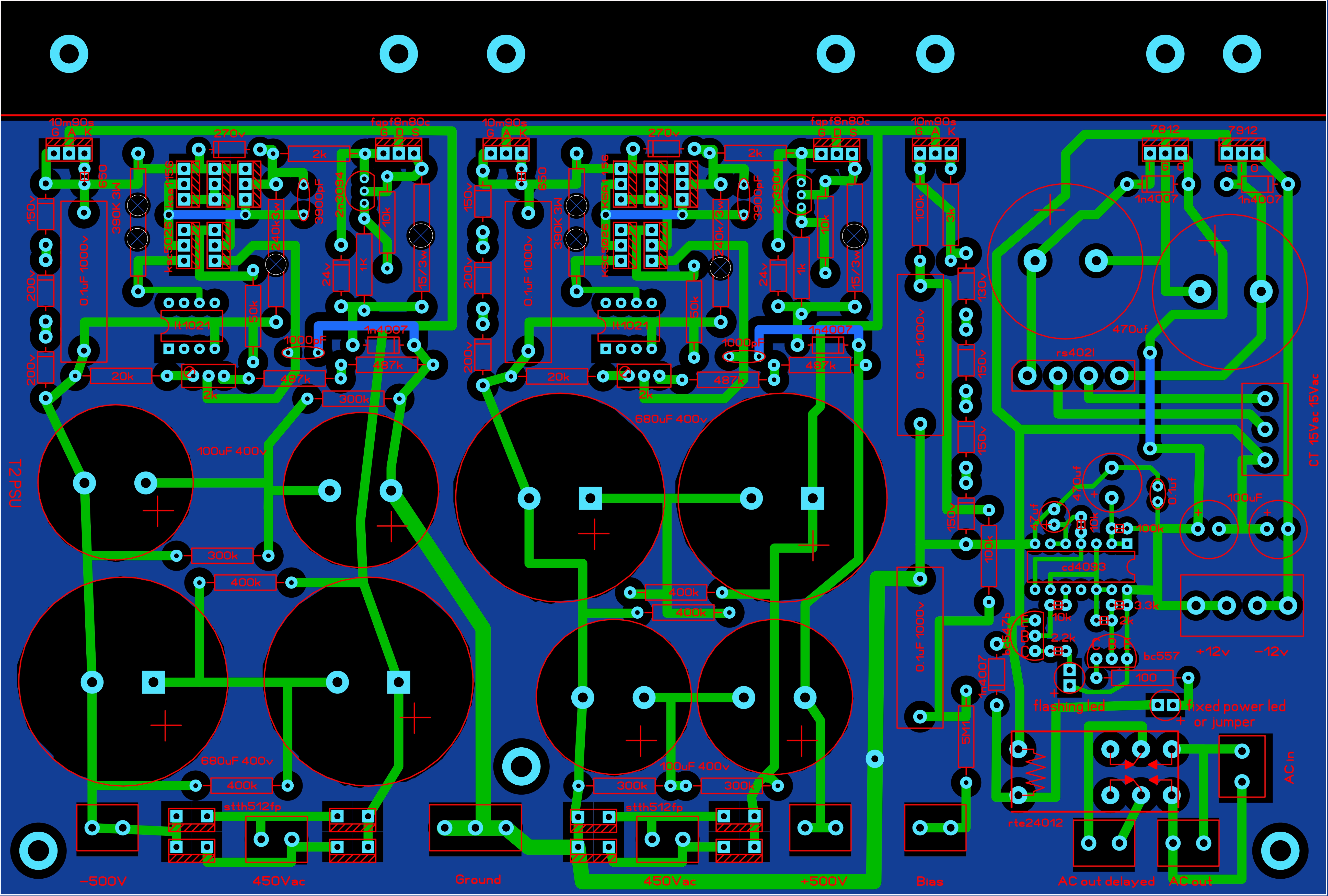
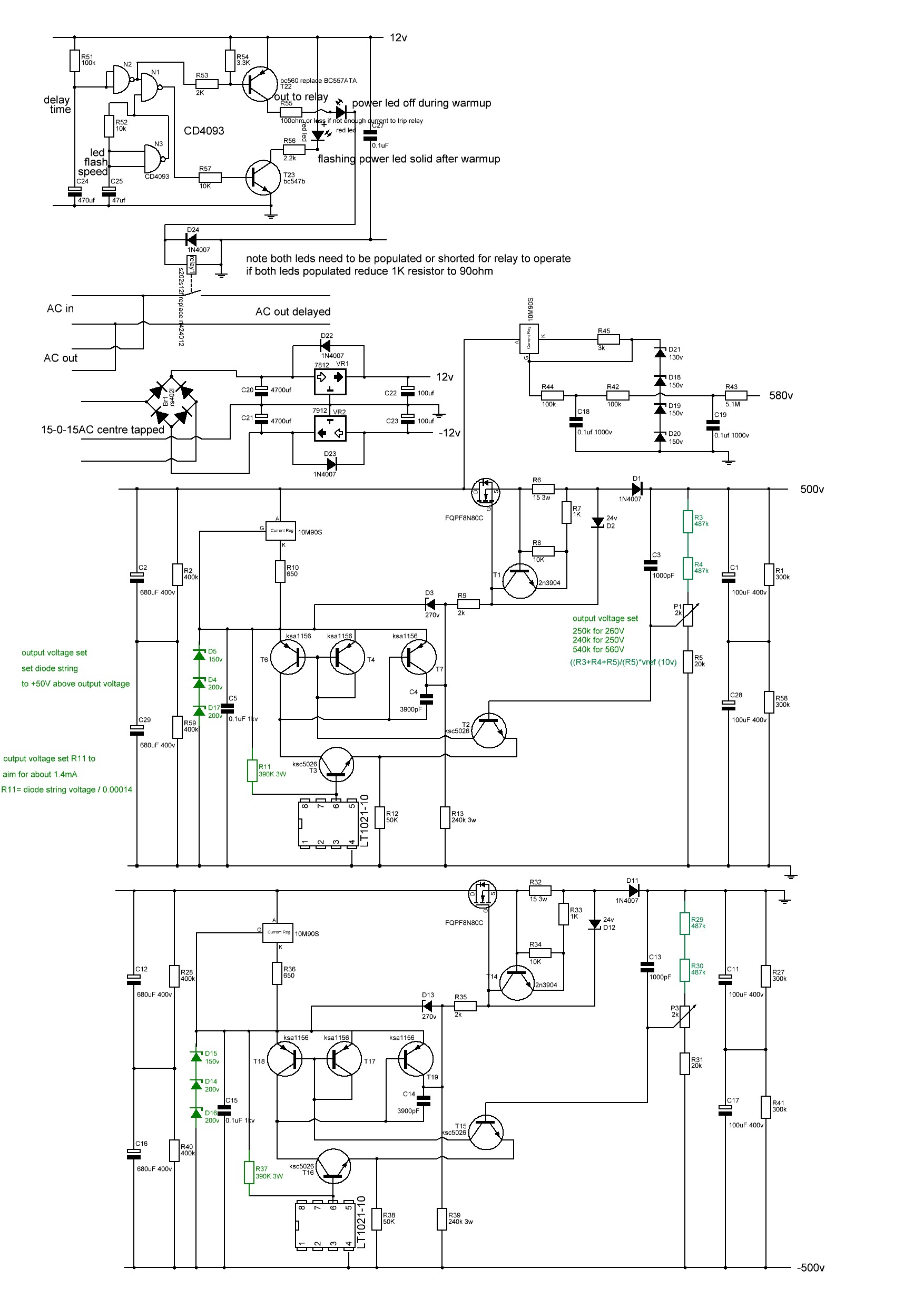
----------------------------------------------------------------------------------------------------------------
This pcb is 220mm wide by 148.5mm deep and contains the low voltage rails, delay and the +-500V rails with the adjusted 3W resistor
t2 kgsshv +-500v, lv, bias and delay corrected.zip
-
3
-
-
3 hours ago, audioguru1 said:
So I built a set and they work! I am however not seeing any adjustment with the 100k trim pots. Same for two boards and the positive and negative side of each. I've checked my work (and orientation), and all seems ok. I could just leave them (they run stable at +/-20v as expected) but i'd like to understand why i'm not seeing any adjustment. Looking at the circuit it seems pretty simple... I know I am probably missing something obvious.
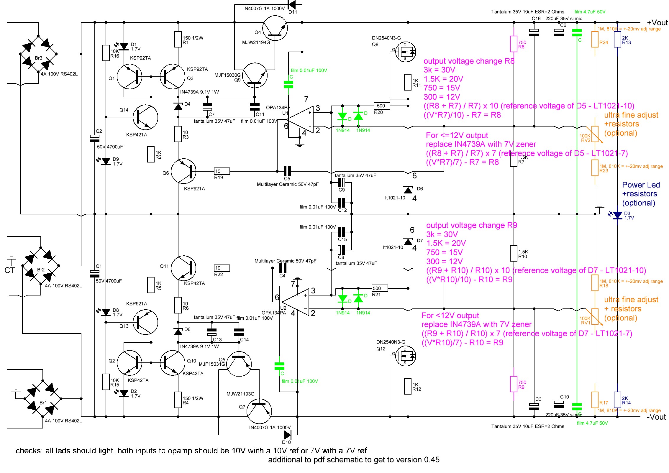
The output voltage is set by two resistors R8/R7 and R10/R9 (see schematic below).
the trim pots make only very small adjustments - a few mV for those who want spot on voltages - there is a trade-off between adjustment range and temperature stability.
If you want more adjustment range decrease the value of R24,R23,R18,R17. 810K instead of 1M for each gives about + and - 20mV adjustment range.
If you want reasonably accurate voltages AND lower temperature drift you can use 0.1% resistors for R8,R7,R10 and R9 with low temperature coefficients (stock resistors are usually about 100ppm, 0.1% are usually around 25ppm) and omit the 1M ohm resistors and trim pot.
-
22 hours ago, micon21 said:
Sorry, but how does the signal get to pin8. I see that the cathode feeds transistor Q8, no signal comes to Base Q8 through R11.
Simplified explanation:
There are multiple methods for changing how a transistor or valve conducts. You can vary the voltage on valve grid or current on the transistor base. Another way is to vary the current supply to the transistor emitter, collector or valve anode or cathode, another way is to vary the voltage at the valve cathode.
.. Just because the valve grid or transistor base does not have audio directly applied does not mean that there is no audio passing through the device....
- Q1 is constant current. Since its emitter has a constant load and voltage applied and so has a constant current available and the base also has a fixed resistor and fixed voltage. Rv1 can adjust slightly the overall emitter resistance and therefore available current to each half of Q1 so some current balancing can be done to compensate for mismatches in the halves of V1 and V2 etc.
- The Q1 current is shared between the second 6922 (V2) (the one which does not have its grids connected to the audio input) and Q4/Q5.
- If second 6922 (V2) pulls more current then less current must be available to Q4 and Q5 since the total current available is constant and visa versa is true if the 6922 pulls less current.
- So the current through Q4/Q5 is effected by the current pull from second 6922 (V2) whos current draw is effected by the audio on the grid 1 of the input 6922 (V1) . Since the second 6922 (V2) supplies the anode current to the input 6922 (V1).
- if Q4/Q5 are effected by input 6922, Q11 and Q12 must also be since they get their current directly from Q4/Q5 and the base of Q11 and Q12 is held constant by the resistor string .. R36, R49,50,60
- If Q11/Q12 have current draw effected by the audio input 6922 then the voltage drop across R11 and R12 and current through R11/12 must also be based on the audio input... since the current through R11 and R12 is directly controlled by the current through Q11 and Q12
- The current through R11 and R12 control the current at the base of Q8 and Q9 and therefore control the current through Q8 and Q9. Q8 and Q9 control the voltage at the EL34 cathode and that's how the audio gets into the EL34s and that's the AC audio voltage than can be measured with an multimeter at the cathode of the EL34s.
-
 1
1
-
On 12/31/2022 at 11:52 AM, micon21 said:
?
Maybe I'm wrong, but I understood it this way: the signal goes only to the first lamp 2pin. output from 3pin.
through the second lamp 6922 signal does not pass, it has a different purpose, and you can use cheaper brands.
EL34 also does not receive a signal, the signal goes through R43, 44
the audio signal goes into the cathode of the EL34 and is amplified by each EL34 by about 9 times. (5.17Vrms into the cathode and 46.7Vrms out of the anode)
-
1
-
-
On 12/30/2022 at 4:23 AM, micon21 said:
Tester measurements are as follows:
lamp one, 1 pin - 74v.
3pin - 2v
The second top lamp: 6pin-200v. 7pin- 61v
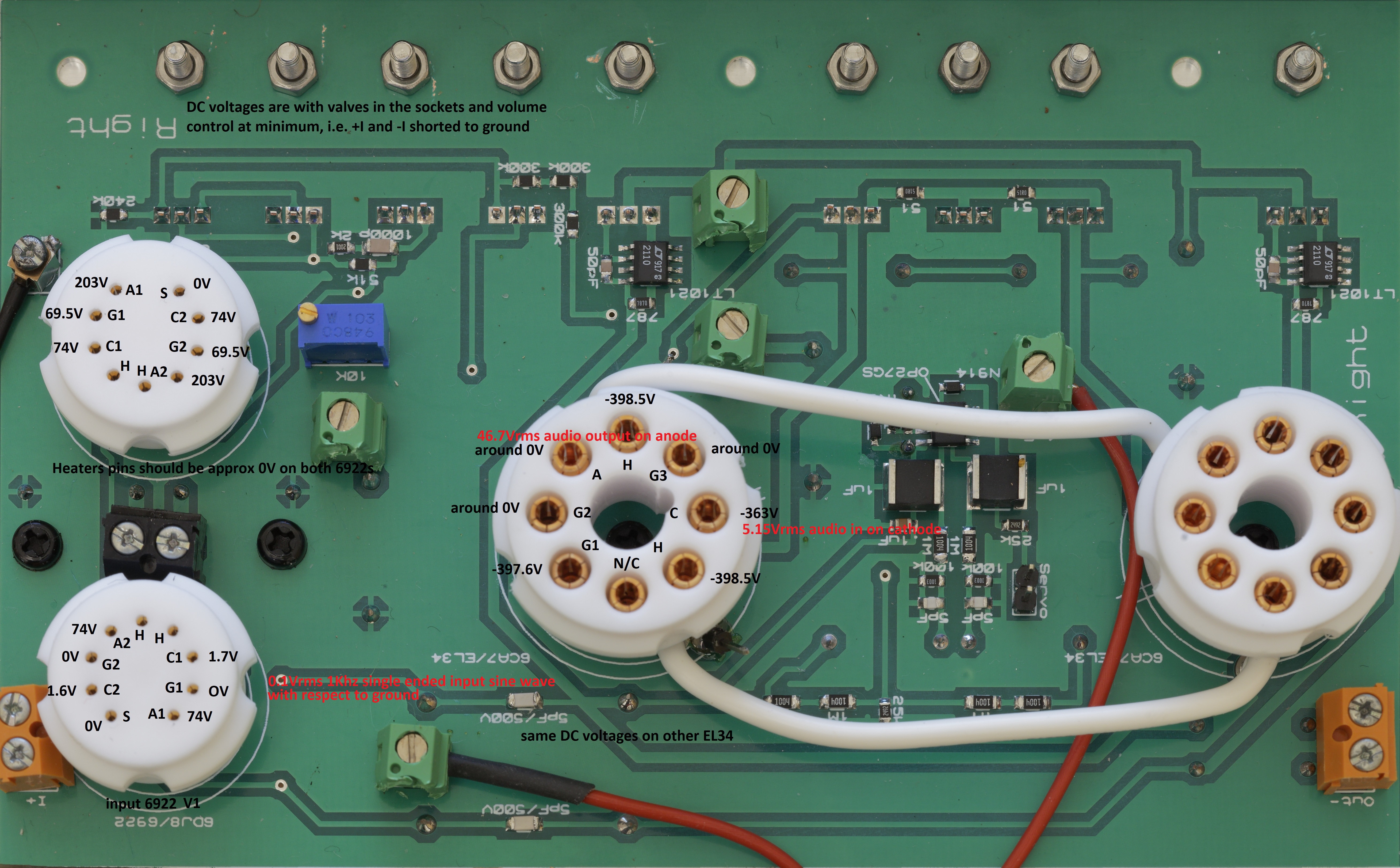
el34, 8 pin - minus 365vTo help people with troubleshooting here are the valve DC operating points measured with respect to ground on a known good stock mini T2. Inputs are shorted to ground. No load on output. All components stock values and DC PSU voltage rails within 1% of schematic when under load. Obviously the two el34s should have identical DC operating points and so should each half of a 6922, the other channel should also match. Exact measured values are going to vary a bit depending upon the valves, exact PSU voltages component, tolerances etc etc.
NOTE the EL34 heaters sit at approximately -400VDC. The 6922 heaters are approximately at 0VDC
I get a signal gain of approximately 940x with a single ended 1Khz sine wave 0.1Vrms input and an output of 94Vrms between the + and - output pins into a 10Mohm (multimeter) load.
Audio enters the EL34s on the cathode and for 0.1Vrms 1khz input I get approximately 5.17Vrms of audio on the cathode, the EL34 amplifies this by about 9 times and gives 46.7Vrms on the anode with respect to ground. The other EL34 operates similarly but opposite phase.
-
1
-
1
-
-
1 hour ago, micon21 said:
?
Maybe I'm wrong, but I understood it this way: the signal goes only to the first lamp 2pin. output from 3pin.
through the second lamp 6922 signal does not pass, it has a different purpose, and you can use cheaper brands.
EL34 also does not receive a signal, the signal goes through R43, 44
you need to consider the current flow....
audio goes into the grid of the input 6922 and the audio effects how much current the valve allows to flow from its anode to its cathode. The input valves anode current supply comes from the second 6922 cathode... therefore the current flow through the input 6922 effects the current flow through the second 6922...
I guarantee to you (in a properly working min T2) the audio goes through the el34s... think about it.. how do we get 500Vrms audio output from a single 6922? A single 6922 can't do that kind of voltage swing.
-
14 hours ago, micon21 said:
Thank you for trying to help me.
I got a good undistorted sinusoid, with a large sweep of more than 110v at the output, with an input signal of 1.2v.
after adjusting the resistors R43, R44, R7, R8.
In the end I replaced 100k with 270k and 100 ohms with 2k.now also on the third leg of the first lamp, I see a nice not crooked sine wave.
This change did not change the voltages on all legs of both 6922 lamps.
i'm glad you are making progress. As originally designed the mini t2 should be able to output about 500Vrms with around 0.02% distortion with about a 0.5Vrms input. At 100Vrms output distortion should be about 0.004%.I think this is what you should be aiming for.
I would also strongly advise that you build the golden reference HV power supply for the amp. Its an extremely high performance power supply and is the core of most of the headphones amps designs here. Its also all through hole and easy to build. It will also provide the 580VDC bias needed for the stax headphones.
-
1
-
-
12 minutes ago, micon21 said:
I understand that it is very important that all resistors match the ratings. I strictly adhered to the specified values.
I used one 197 and one 356, as JoaMat recommendedhow about the transistors, op amps and voltage references are they also the same as the schematic?
-
1
-
-
13 hours ago, micon21 said:
OK, and I'll take care of the power supplies, make them adjustable, what to do 400, 460
I had microcircuits to make +12 and -12.
I assumed that if I feed 12 instead of 15, it won't make much difference. or am I wrong?have you built the amp board using the components and values recommended in the schematic? or have you also used different values or components?
-
29 minutes ago, micon21 said:
Before connecting to the board, I set the necessary voltages on the stabilizers. When I turned on the board, all the high voltages dropped, +368, -408, 208. Since they dropped evenly, I believe that this is not the reason for the very small output swing.
the psu clearly has poor voltage regulation. The voltages have not all decreased by the same percentage but I don't think this is why you have almost no voltage amplification.
if you connect the test signal to the + input and ground the - input do you get a similar output on both out + and out -?
if you connect the test signal to the - input and ground the + input do you get a similar output on both out + and out -?
how are the + and - 15V dc rails under load? (the -15v also acts as the input 6922 anode current sink)
and what frequency is the oscillation when both + and - input are grounded?
-
3 hours ago, micon21 said:
Thank you for helping.
I have to use the translator, it doesn't give me a full understanding of what you wrote, alas.
sorry. It is not at all clear what you mean >I assume you scope is set for 10M input and NOT 50ohm... also I assume you scope probes are set to x10 so you don't overload the front end of your scope.some (usually expensive) scopes have the option of setting their input impedance to 50ohms or 1Mohm. stax headphones are high impedance and draw very little current from the amplifier and so the scope should be set to high impedance. Setting the scope to 50ohm input impedance would draw far too much current and risk damaging the scope. If your scope does not have switchable input impedance then it probably has high impedance inputs by default.
Stax amplifiers are can output 100V or more of audio. Most scopes with 1:1 probes will overload and can get damaged with that level of input. X10 probes reduce the voltage by 10 times providing more protection for the scope as well as raising the input impedance from 1Mohm to 10Mohm (usually).
3 hours ago, micon21 said:There is no regulator on the input of the amplifier. I connect the signal directly from the player. I look on the first leg of the first 6922 +67v, on the third leg 0.6v
on EL34 8pin -334v// signal 1v, on 1pin signal 3.4 von the second lamp, 1 and 6 pin +183v
on pins 2 and 7 +57vApparently, the first tube does not amplify the signal
-
7 hours ago, micon21 said:
I understand correctly, the signal goes like this?
no thats just the feedback loop from the output to the input valve. the actual audio signal path is far more complicated.
the output is provided by the el34 valves. Powered from constant current devices connected to their anodes/plates.
-
1
-
-
3 hours ago, micon21 said:
after full power on, on the output, tweaking 10k, makes it possible to make a minimum of +3.5v and -4.1v. then fed the signal 1000Hz 1v - on the output received a very small signal amplification, no more than 5 volts...
have you designed the amp side as single ended i.e. rca input or balanced i.e. xlr input?
if you are running single ended then the - input side needs connecting to ground.
assuming that is ok next check the input (i.e. grids) on the 6922s that connect to the inptut and check you actually have a signal on both.
next check the input i.e. grid of the other 6922s to check you have an input to them
next check the grids of the el34s to check they have an input
this should give you an indication of where your signal is disappearing.
I assume you scope is set for 10M input and NOT 50ohm... also I assume you scope probes are set to x10 so you don't overload the front end of your scope
I also assume you have checked all the dc voltage inputs to the amp board and they are correct.
have you got a volume pot on the input or are you feeding 1Vrms directly into the amp?
if i remember correctly the min t2 is about x1000 gain
-
1
-
-
5 hours ago, micon21 said:
The circuit I showed as an example. for mini Т2 voltages are different. I made three of these, of course first adjusted the necessary voltages.
I have an oscilloscope, it will tell me if the board is working or not.
there is a jumper on the board, SERVO ENABLE, should it be shorted the first time it is turned on? if it is not connected, what happens?
I understand correctly, the signal goes like this?
the automatic servo is limited in the range it can compensate for. So removing the jumper allows you to manually adjust so the servo does not need to do much work then you can add the jumper to activate the automatic servo.
-
1
-
-
3 hours ago, micon21 said:
Hello everyone.
I finally had the opportunity to do a mini t2. to begin with soldered only one board, that is, one channel.
iMaybe someone made a record of the voltages at different points on the board.
normally I would be happy to help, but I am at my parents and don't have access to a mini T2 to measure until I return to my home.
im not sure of your level of experience, so my apologies if some of this is obvious
0. be aware working on a powered amp exposes you to the risk of electric shock and you should only be doing this if you know how to be safe and have a good quality multimeter.
1. I would build and check the psu is working without it connected to the amp. I assume you have build golden reference high voltage supplies. Advice on these can be found on the thread for the gr hv.
2. before i would think about powering the amp board I would carefully inspect the solder joints looking for bad joints and solder bridges with a handheld magnifier or better a microscope.
3. I would verify as far as possible the component placement, orientation vales are correct. If you have a set of very fine spring loaded probes like those sold by probe master you can check for continuity/shorts between components referencing the schematic.
4. i would strongly suggest that testing is initially done on using variac and slowly bringing up voltages to their normally working levels, measuring psu rails and looking out for smoke, bad noises etc.
5. i would strongly suggest using cheap valves for initial power ons until you are confident the amp is stable and working correctly.
6. I would monitor the dc offset (dc voltage between + audio output and ground) and dc balance (dc voltage between - audio output and + audio output)
7. I would not think about connecting expensive headphones until I have put in some audio test signals and looked at the output on a oscilloscope and had the amp running for at least a few hours.
8. if you have a temperature probe, its also worth measuring the transistor case temperatures and the temps of any high wattage resistors..
if you still need specific voltages I should be able to help after jan 9th
good luck
-
2
-
-
pray to the deity of semiconductor manufacturing (in a reverential voice tinged with grief)....
🙏
oh Nosemi please hear our plea for our DIY hobby....
in the name of silicon
please bless us with some manufacturing
and fill up our inventories
In the name of NPN and PNP
blessed are the mosfets, depletion or enhancement
for the DIYers shall inherit 10M90S
and it was good
Let not the ebay scammers rebrand and re-etch
for they will be accountable to silicon
and burn in the foundries of ixys
for all eternity
Let it be known Toshiba and NEC will escape Renesas
Sanyo and Fairchild will rise again
and return to us all
for now and for evermore
Ahmen.
(The DIY hymn book chapter 11 covid 19 to recession 2008 verses 1-4)
-
6
-
-
2 hours ago, bbest said:
Mouser has changed delivery date for IXCP10M90S on 08-Aug-2023. So where to buy it?
about the only hope is from a forum member or take chances with fakes on ebay 😞
-
2 hours ago, Grahame said:
wow AI is even more useful than I thought..
-
28 minutes ago, audiostar said:
Ok, right-click and then "save as" works, but then the file needs to be renamed to .pdf in order to be able to open it. Chrome saves it on macos as undefined. Must be something with the formatting thats wrong.
on windows chrome saves with correct extension....
-
1 minute ago, RudeWolf said:
What did you load the Dynalo with? I find that 30/300 Ohm loads work nice and you need to come up with a voltage target that's relevant for headphones.
P.S. Am I the only one who can't download these reports? My browser just loads for a little bit and then nothing, the download doesn't start.
Im using windows and chrome. I right click on the download, select open in new window and then hit enter in the url of that new window to download....
-
1
-
-
3 hours ago, skullguise said:
The Audiophile Society has a free download of WAV files sampler with Chesky & other music and mixed using "3D Mega-Dimensional Sound" techniques.
https://theaudiophilesociety.com/products/the-audiophile-society-welcome-sampler-wav-download
Downloaded but haven't listened yet....
the speaker mixes through headphones sounds absolutely terrible, artificial and very very strange sounding bass, absolutely horrible, imaging is all over the place sounds like someone has strapped the worlds worst setup sub woofer behind you.
Headphones mix sounds ok. But there is nothing pure acoustic and simple, like solo piano or voice to listen to... just sounds too showy. The Strauss trebble end is slightly bright and hard, bottom end of the bass is rather boomy and feels compressed in the middle, completely lacks micro dynamics... sounds like its mastered to be played really loud, apart from the lack of tape hiss I don't find it in any way batter to sympathetically transferred 1960s analogue recordings.
Aayushi Karnik - Solid Ground (headphone mix) the voice is just lost in the mix sounds like the singer is behind a curtain far far behind the main instruments.
Mark Sherman & Joe Magnarelli - Suddenly (headphone mix) piano sounds strange, again bass boom and sounds electronically processed..
Paloma - Ode to Joy (headphone mix) her voice sounds like she's shouting down your ear the peaks in her voice are mildly painful.
EX38 - Ring No. 5 (headphone mix) WTF I cant tell how much is the electronically generated instruments and how much of it is the effect of the recording. Feels like im trapped inside sampled midi instrument hell.
none of the tracks have a sense of natural acoustic, are dry or artificially dried but then warmed up with excessive bass and reverb to simulate an acoustic. I think this is just another example of electronic fuckery like the short lived DG 3D sound processing on a few classical cds... its not about natural sound its about lots of sounds....
-
1
-
2
-
-
mouser currently has ksa1156.
radio spares has STN9360, FJPF2145TU and FQPF8N80C
-
2 hours ago, lupoal said:
Hi,
I'm asking for help because I can't understand ...
so i installed in my 006 two tung-sol 6sn7gtb tubes (American NOS)with about 250 hrs on them (so out burn-in but new), I replaced the adjustment trimmers with multiturns to have more control, I use a ceramic screwdriver, my mains voltage is 220Vac constant, I let the amp warm up for at least an hour (with signal on and volume at about 2) before calibrating, put the volume to zero and select an input with no signal (the 1, which is connected only the 3). .. tester in Vdc...first I adjust the balance or then the offset, then balance again and then offset...then I switch to the other channelnow this happens to me
- between with and without cover the read value varies sometimes even more than 2V, and it varies all the time...it swings back and forth...especially on balance
- even in constant condition, e.g., always without lid, the adjusted voltages never stand still...they constantly fluctuate back and forth...e.g., -0.8 to + 1.4...then it slows down...then it picks up again
- from one day and the next I do not find the same values againquestions:
- am I doing something wrong? should I follow a different procedure?
- what is the target value to reach for balance and offset? (I read of people adjusting to 0.25V...but in my experience it is absolutely impossible)
- what are the acceptable target values without having to continually intervene with calibration?thank you in advance for your help 🙂
Stax headphones are designed to take hundreds of volts of audio signal , a small offset of a few volts are absolutely not an issue.
The offset will change with temperature. ALL amplification devices are somewhat temperature sensitive - including valves and transistors.
you can demonstrate this easily, just blow gently onto the valves and what the offset change... This is why you are getting different results with the cover on and off. So don't worry you are not going to hear any difference or cause any damage to the headphones or shorten their life...


Dynahi Build Resources in 2023?
in Do It Yourself
Posted · Edited by jamesmking
in general there are no build guides unless a forum member explicitly makes one. Here is the link to the forum thread for the amp. I strongly suggest reading through it all... the threads document the evolution, modification and problems builders have.
https://www.head-case.org/forums/topic/9768-kg-balanced-dynahi-build-discussion-thread/#comment-468974
schematics can be found at
https://drive.google.com/drive/folders/0B7egryukiT7_TFlEQlBRejdVdDQ?resourcekey=0-nGWwBYQ_Uivj-ciBLYMeaA
and gerbers to have pcbs made:
https://drive.google.com/drive/folders/1r3g2TAtBUaBdiMorTWX7yYgeJ7maQbYW
Also consider that people post schematics, their own gerbers etc in the thread sometimes.
Also be aware that if you need transistors which are no longer manufactured and only available as new old stock, there are many many sellers on ebay etc selling FAKES, which are look alike transistors with the original markings removed and the markings of the NOS transistor silk screened or laser etched on to them. These fakes of course will fail on first switch on... So if you need NOS components consult the forum before buying from a seller.
Sometimes there are more then one version of an amp, one using NOS and one using modern components, but the speed through hole transistors are being marked as obsolete or end of life by the manufacturers mean that its a constant struggle to have amp designs that only use modern available parts.
There are some forum members with stocks of NOS components who are sometimes willing to sell to members, in general what they don't want to do is to sell to someone who will then just resell the components at higher prices on ebay etc, if they are going to supply they expect the components to go into a build or be held as spares for an existing build since the supply of many genuine NOS components is getting very very low and often there are no modern drop in substitutes. So sometimes you have to be in the forum for a while and post pictures of your builds so you can show you are a genuine DIYer and not a high price reseller scalper.
often builders get the bare pcbs made by Chinese companies like JLCPCB who have a minimum order quantity of 5, so sometimes people have spare pcbs, so its often worth asking in the forum if anyone has a spare. There are also on going parts shortages so sometimes its possible to do a parts swap with another DIYer is they have spare of what you need and you have something they need....
Good luck and welcome.
(P.S. the moderators do a very good job of keeping junk sellers, bots, scammers, advertisers, spammers etc out of the forum. There is a wide range of threads not all DIY related and its generally frowned upon to do politics etc in a build thread.).