plaurids
-
Posts
88 -
Joined
-
Last visited
Content Type
Profiles
Forums
Events
Everything posted by plaurids
-
Hints on maintaining / improving my Stax SRM-T1S
plaurids replied to plaurids's topic in Headphone Amplification
Quite a few things to report: Last Friday I finally mustered the time to increase the CCS current to 6mA/section as planned. The voltage measurements during tube rebiasing behaved as expected - the offset (TVR1) measurements were unchanged by the plate current increase, so only minor adjustments were made, whereas the balance (TVR2) measurements shifted by about 60 volts. After recalibration and the usual tube drift to be dealt with in 4-5 rebiasing sections with one hour in between each other, I proceeded to testing. My initial impression after a few days (with the cans properly charged by the new energizer setup) is that there was an overall improvement in dynamics, instrument separation, imaging and layering as compared to 4.9mA/section. Soundstage depth and width didn't seem to change much with that, though. The 007A now sounds more resolving and less constrained, regardless of the volume level. However, I cannot help but feel that there was a certain harshness and a bit of a loss of timbral refinement as compared to the original 6CG7 tubes, especially the Toshiba / Raytheon ones. I had that feeling already with tube rolling to 6SN7GTB's alone, and increasing the current to 6mA/section didn't seem to change that. Still needs more listening to be sure, but I'm feeling increasing confident that my initial impression in that regard is correct. On the other hand, my memories are still mixed up with the sound from the 007 Mk1 (which hadn't been paired with the 6SN7GTB's before the sound element damage), so that may also account for the difference. Maybe in a couple of months I'll go back to the Raytheon 6CG7's @ 4.9mA/section just to be sure. For the time being, though, I'm evaluating the pros and cons of keeping the current setup. Edifier told me they've contacted Stax in Japan about my 007 Mk1's problem and are awaiting a response from them on how to proceed. Let's see... In the meantime, I've decided to try using the 007 Mk1's earpads on my 007A. I took the newer earpads that were sitting on my 007 Mk1 and returned the older (stock) ones (recall that my 007 Mk1 came with an extra pair of Mk1 earpads). If the 007 Mk1 is sent to repairs, it has no missing original parts as it stands apart from the headband arcs, but I still get to play with how the Mk1 earpads affect the 007A sound by themselves. As such, I decided not to swap the earpad springs or take off the port lids from the 007 Mk1 (to replace the blu-tac stuck into the 007A's ports) - yet. I'll only do so if repairing it turns out to be unfeasible. Aesthetically, there is indeed some color mismatch - the brown Mk1 earpads pair better with the Mk1's champagne finish than with the 007A's silver finish - but I don't care. I expect at least some soundstage, imaging and separation improvements with this mod, based on my Mk1 impressions. Will update here in the near future with how that goes. Ok, time for a quick update on first impressions right after putting Mk1 earpads on my 007A. I simply couldn't wait. It changed the sound more than I expected, and in retrospect I think I understand why. Indeed the soundstage was enlarged, but not to the width and depth of the 009S. However, the most important (and, at first sight, unexpected) change is that the perceived harshness and lack of refinement after tube rolling to the 6SN7GTB's were simply due to the fact that the 007A drivers were then too close to my ears. The extra thickness of the Mk1 earpads mostly solved these problems, to a point that timbral refinement now seems to be about on par with the Raytheon 6CG7's (pending confirmation after a longer listening period). The earpad seal has also improved, but perhaps not up to the degree of the Mk1 - does this mean that the Mk1 port lids work better than the blu-tac mod on the 007A? Or do the wider earpad springs on the Mk1 also play a role in improving the seal? I don't know... Need more time to evaluate this and other sound aspects (will update again in the near future on that), but I've already been able to learn this: the 6SN7GTB's increased dynamics seems to require the 007's drivers to stand farther from one's ears than the stock earpads can make it for the combo to sound its best. The Mk1 earpads provide that missing distance, and its superior seal guarantees that no dynamical information is lost. Update - March 18th 2023: just to report on a more consolidated set of impressions on the SRM-T1S with the CCS's @ 6mA/section loading the Tung-Sol NOS 6SN7GTB output tubes and driving my (port modded) 007A with Mk1 earpads, after about three weeks of continuous listening. Overall, the less voltage-constrained tubes driven at a higher output current compared to stock led to improved dynamics and spatial resolution (instrument separation, imaging and layering). Now the 007A can be driven both at lower volumes without sounding too dark and at higher volumes without losing frequency response. The rig now simply feels more juicy, so to speak. On the other hand, I still have the feeling that I've lost some timbral refinement as compared to the 6CG7 Toshiba / Raytheon tubes @ 4.9mA/section. To be completely sure, I'd need to have my 007 Mk1 back since the latter impression was established while running the Mk1, but that'll take a while. No response from Stax / Edifier yet. In the meantime, I'll keep using the current setup. It may end up being a pros/cons situation regarding both output tube setups, but cannot tell that with certainty yet. Update - March 25th 2023: in due time, I've also noticed an occasional shoutiness in the upper mids, depending on the recording. Curiously, this is an impression I also got from the Mk1 with the 6CG7 tubes in the first weeks of hearing, which leads me to believe this has to do with the effect on tuning from using Mk1 earpads (contrary to my former belief on the matter), rather than the tube rolling. -
Hints on maintaining / improving my Stax SRM-T1S
plaurids replied to plaurids's topic in Headphone Amplification
After having a look at the Japanese Stax repair page (with the help of Google Translate), I learned that Any international inquiry regarding servicing ( / getting parts for?) Stax products must go through the official Stax distributor in one's own country (that was the only piece in English in the whole page, by the way); The 007 Mk1 can still be serviced by Stax in Japan but with possible substitution of parts. I reckon that in the particular case of the 007 Mk1 this includes the sound elements - they're indeed probably replaced by current Mk2 sound elements. My email contact with Edifier on my issue wasn't helpful, so yesterday I paid a visit to Edifier's showroom in São Paulo. They agreed to have a look into how to contact Stax to diagnose (a bit moot after one sees the pictures above) and to have a cost estimate on the repair. Let's hope... My impression is that nobody came to them before for this since they started distributing Stax products in Brazil... There was a good thing that came from that visit already, though: they had a small listening room full of Stax gear, among them the SR-009S, so I could listen to it for the first time. It was powered by the Stax SRM-700T energizer and sourced by the famed (or infamous?) PonoPlayer DAP, spearheaded by Neil Young's PonoMusic until its demise in 2017 (my first time seeing one of those as well). I've listened to the following tracks, which I had a good memory from listening to them with my 007 rig: David Bowie, Space Oddity (2015 remaster); The Doors, The End; Yes, Hold On; Glenn Gould, Toccata in E Minor, BWV 914 by Johann Sebastian Bach. I know I'm about to undertake quite a tricky comparison - I'm actually comparing two completely different audio chains, not just the cans. I'll try to make the best out of it. The comparison will be mostly against the 007A since my Mk1 has been out of commission for a while and I don't trust my impressions so far back in time with enough details to serve that purpose. Even though I had never listened to the PonoPlayer before, I do know it's powered by the Sabre ESS9018K12M DAC, which is inferior to the newer and more powerful ESS9028 PRO DAC in the Fiio X7 MkII DAP, which I do happen to own. Since I can safely say that the Fiio X7 MkII is quite inferior to my RME ADI-2 desktop DAC in every way except perhaps on soundstage rendering, which is somewhat wider on the X7 MkII, I believe I don't need to fear any comparisons on the DAC side (badumtss). Both cans are very different. The 009S is quite comfortable with the right adjustment on the headband, but you need to find the precise angle to put the headband on for a proper seal. There is also significantly more space for the ears inside the earpad cavities than with the 007A, perhaps even a bit too much (the Mk1 hits the sweet spot in that regard). Regarding sound, the first thing that came to my attention about the 009S was its soundstage - it's significantly wider and deeper than that of the 007 (even the Mk1, I daresay), probably to a large extent due to its earpads. The directional imaging was also superior, seemingly due to the wider perceived soundstage. However, the layering was clearly inferior - there was only "really close" and "quite far" with the 009S, unlike the subtle multilayered imaging of the 007 as already reported by Birgir here on HC. If you take into account the 007's more compressed soundstage (at least in my rig), it only makes that even more impressive. The 009S is ever slightly more resolving than the 007A to my ears, but not sure if that difference is enough to make it more resolving than the Mk1. Instrument separation is comparable, maybe with a slight advantage to the 009S. Regarding bass, there is no contest - the 007 clearly wins, the 009S's bass is just too thin and lacks slam. The energizer may be also playing a role here - the SRM-700T uses the same tubes I'm using on my T1S (a pair of 6SN7GTB's) but it drives them at a slightly higher output voltage (340V instead of the T1S's 320V) and, more importantly, a higher plate current (each tube section's plate is loaded by a Dale NS-7 1% 7W 47kOhm resistor, which amounts to 7.2mA/section). Increasing the CCS's current to 6mA/section as planned for the near future may improve things on my side. With 4.9mA/section I still think that the Raytheon / Toshiba 6CG7 tubes sound slightly more refined on the T1S, despite the clear improvements on frequency response both at higher and lower volumes with the Tung-Sol NOS 6SN7GTB's. Regarding timbre, it's a more nuanced matter. I really liked the 009S with solo piano in Glenn Gould's track - the wider soundstage together with that makes for quite a vivid impression of a grand piano in a concert hall, whereas the 007 sounds more like the instrument is in a studio room or perhaps as if you were sitting on the performer's bench. Obviously, it doesn't feel as if you were playing the piano. No sound transducer can convey that feeling - you largely listen to it with your bones through your fingertips, as well as with your ears, as you play. For human voices, though, it's a different story... The 007 is definitely more natural and pleasant. I'd need to listen for more varied tracks and a longer period of time to form a more complete picture of the 009S's timbre against the 007's. That will have to wait for another visit to Edifier's showroom... Hopefully they'll have a SR-X9000 for testing as well by then...- 107 replies
-
- 1
-

-
- stax
- maintenance
- (and 1 more)
-
Hints on maintaining / improving my Stax SRM-T1S
plaurids replied to plaurids's topic in Headphone Amplification
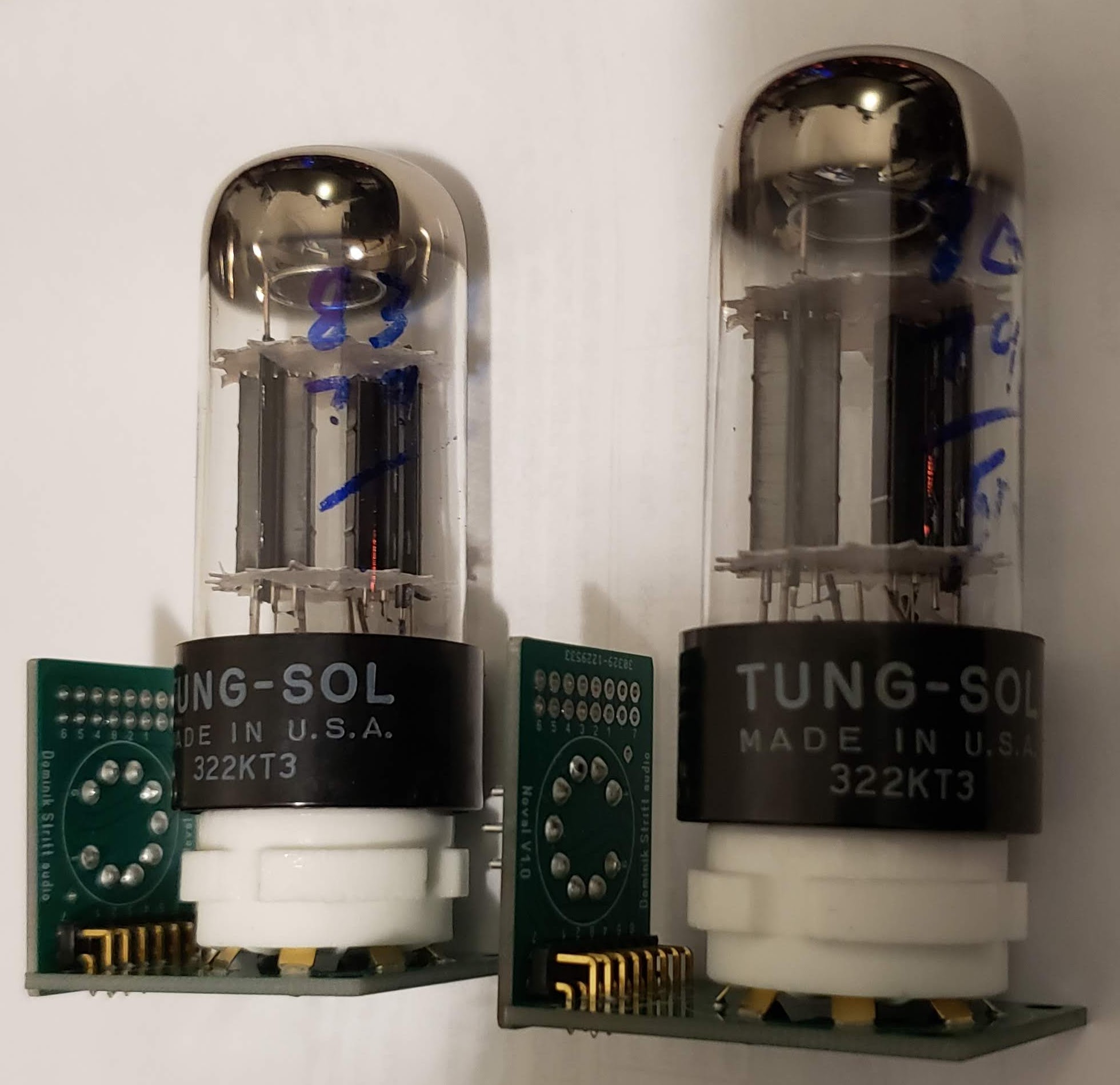
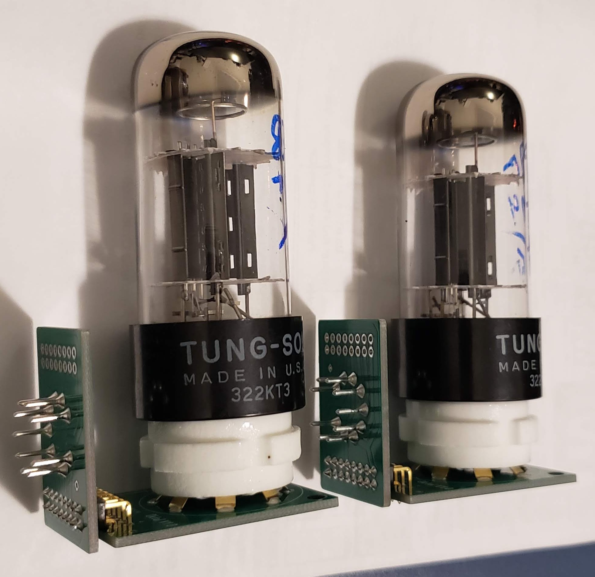
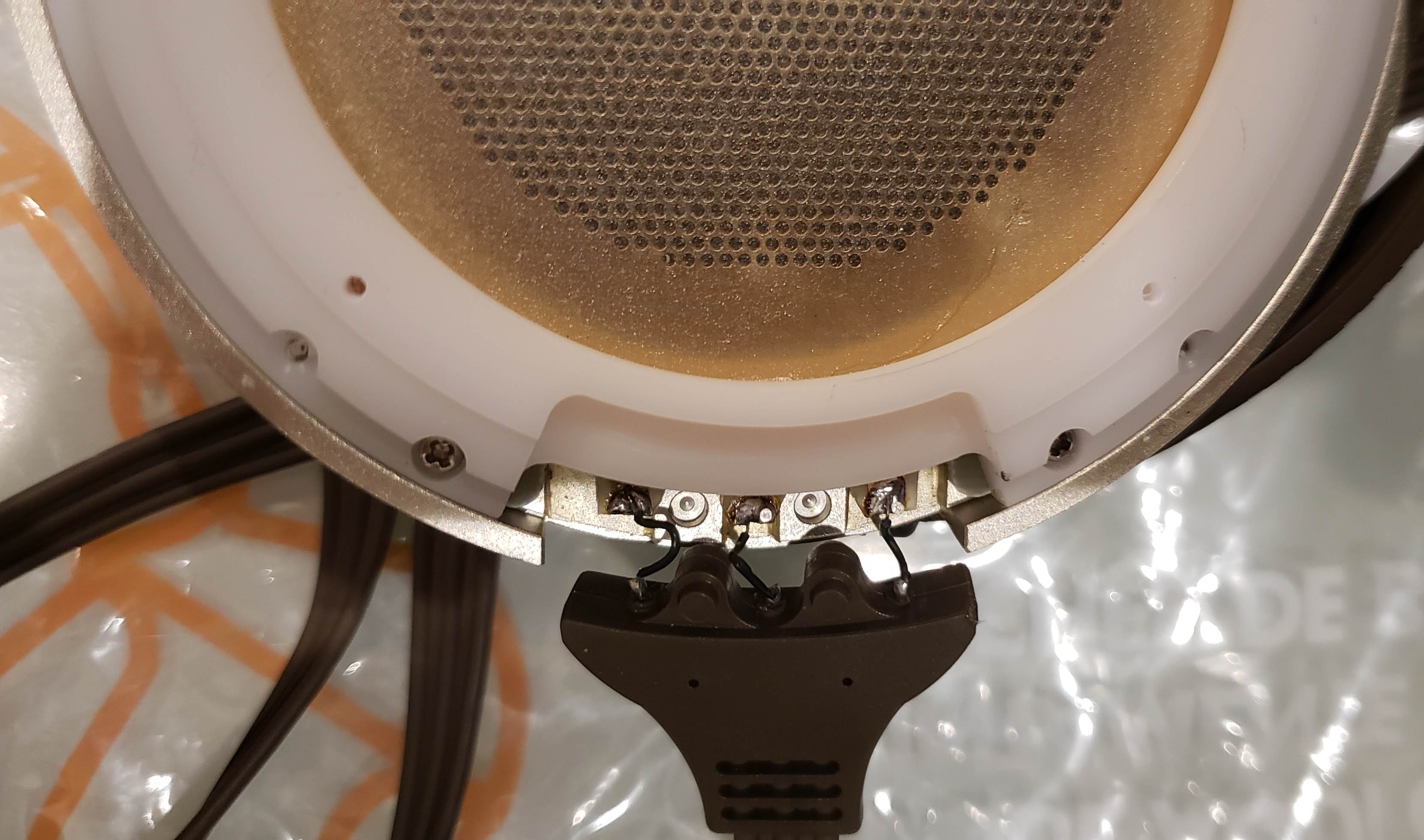
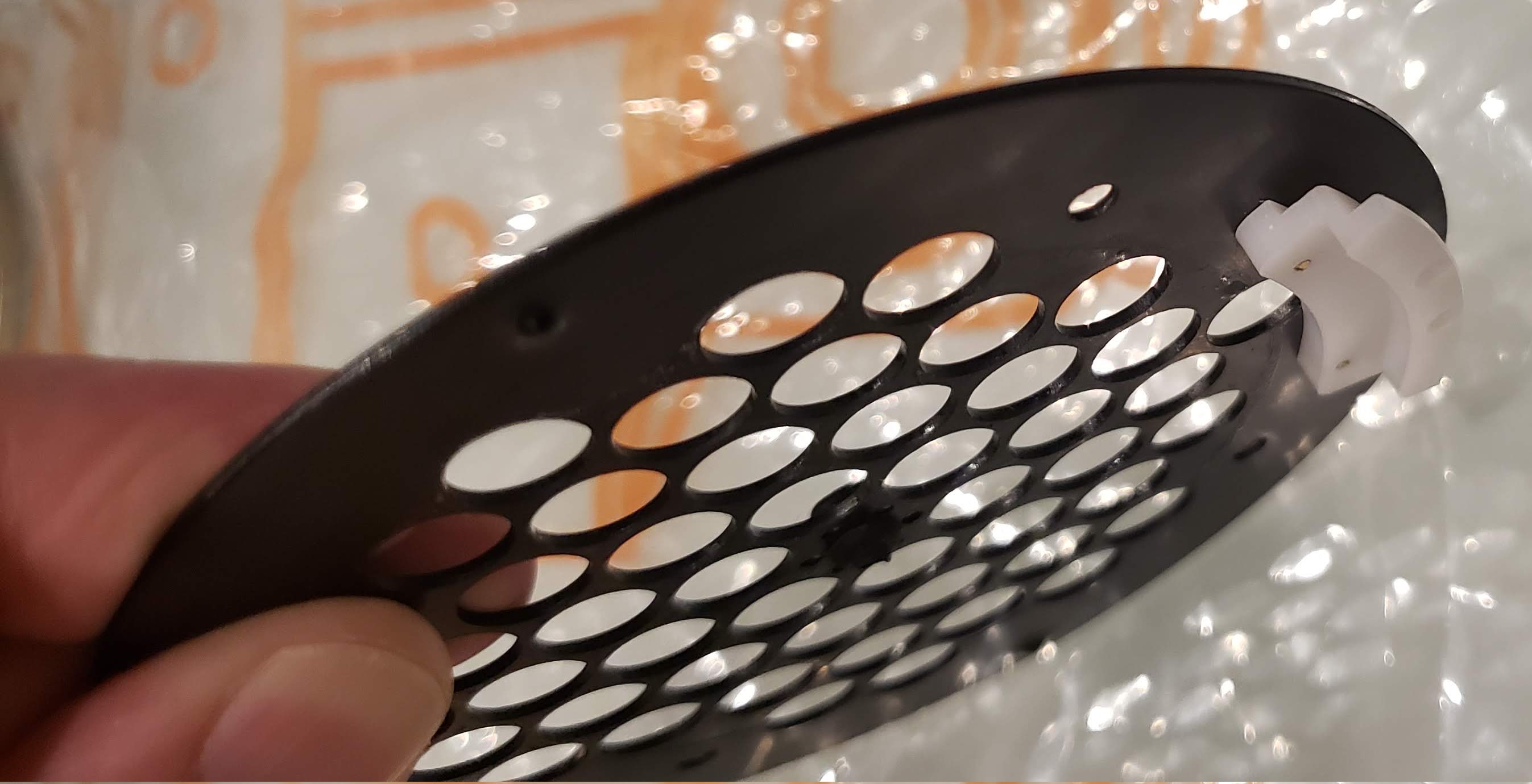
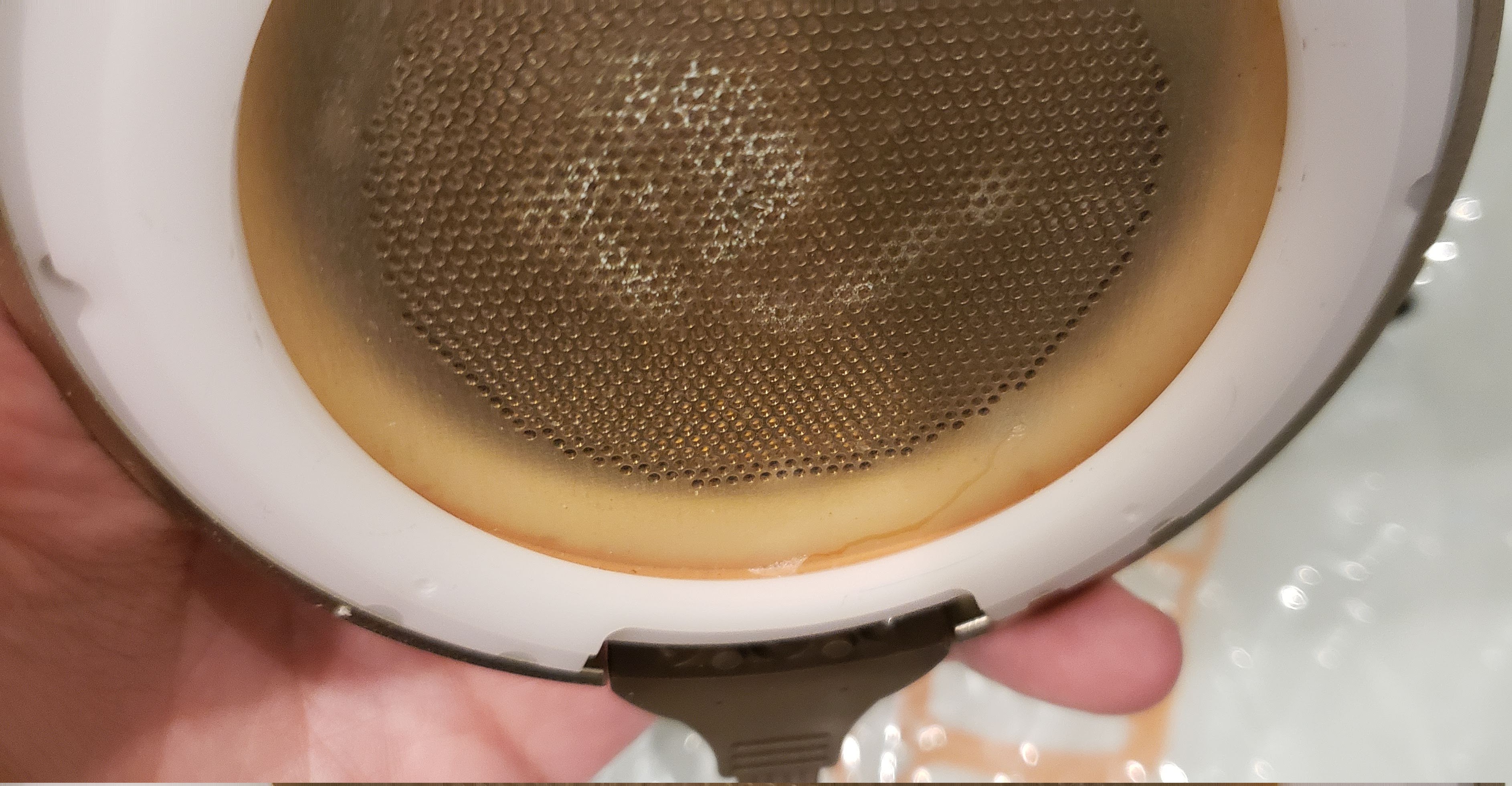
Some good news and some bad news... First, the good news: I've just replaced the fuse holder and standard 6x30mm 1.5A fuse by a Gustard 5x20mm 1.6A fuse, and my NOS Tung-Sol 6SN7GTB tubes arrived yesterday. Will tube roll soon, first with just 4.9mA per tube section to see what improvements I may get with just that. After that, I plan to recalibrate the CCS's to 6mA per tube section if I like the results. As partially reported above, each tube has a tall bottle, black base, white labels, triangular black plates and a top O-ring getter. The label reads 322KT3 on both tubes. Here they are, sitting already on their respective angled adapters. Will update this post with my first impressions later on... Update (January 19th 2023): Ok, time for those first impressions - all of them on the SR-007A (see next paragraph for the depressing reason for that): the first thing I've noticed is that, unsurprisingly, I can raise the volume higher without losing detail, a big deal especially when listening to more compressed tracks. At the same time, the tracks feel more "whole" at lower volumes. This probably means altogether that the energizer is struggling less with driving the SR-007A, which is good. I have the impression, though, that the Toshiba / Raytheon 6CG7's deliver slightly cleaner bass and transients, but I could be mistaken... Cannot say much about the soundstage yet because of the forced change away from the Mk1. The aforementioned perceived loss of bass and transient clarity may be also due to that. May need to go back and forth between the 6CG7's and the 6SN7GTB's another couple of times in order to reach a definite conclusion. Now for the (really) bad news: the right sound element of my SR-007 Mk1 is officially gone. Spent a few days on holidays away from home; when I returned, I noticed a sudden channel imbalance to the left. First I thought it might be a tube bias issue, since I had replaced the tubes less than two months ago (maybe the new tubes were worn out?), but rebiasing didn't change anything. Swapping tubes didn't change the imbalance either, so I decided to plug in my SR-007A. No imbalance at all. Fearing the worst, I decided to remove the right earpad and its attachment panel to see if some wire was disconnected from the driver (a common cause of channel imbalance). What I found was much worse. The wires were fine (in more than one way, though - they look so damn fragile... Was that really necessary, Stax?), but to my horror there was a tear in the protective membrane just above the wiring, and signs of mold inside the driver element. Most likely the mold (together with dust and who knows what else) reached the center membrane and is causing the loss of response. I have no idea how that tear happened... I've used the Mk1 for quite a few months with no problems at all regarding the drivers, so I think it's highly unlikely the unit was sent by its previous owner like this. Maybe it was the suction from the Stax farts that ended up causing it? Shouldn't the drivers be able to cope with that? Curiously, the left driver was the most farty one and it's just fine (one of its wires broke during examination, though... just needs some soldering but I'm too depressed to deal with that right now). It seems to me that the right sound element is beyond repair... which raises a new set of questions: Where to find a replacement SR-007 Mk1 sound element, and how much does it typically cost? The white resin driver assembly seems no different from the one on the Mk2, apart from the port cover attached to the earpad attachment panel. If I can only find Mk2 sound elements, is it ok to change just the defective element? Or will the sound signature change (and thus become imbalanced) because of that? If the only way to get the sound element replaced is by sending the unit to Stax in Japan, how should one proceed to do so? I'll try to ask Edifier here in Brazil if they can help somehow... Any other ideas? In the mean time, the 007A will come back as my main listening rig, and the Mk1 will remain sealed in a plastic bag with a healthy load of silica gel bags inside its carrying case until I can find (and afford) a solution. If I find out that my 007 Mk1 is beyond help, I may decide to experiment using some 007 Mk1 parts on the 007A in order to get at least a somewhat wider soundstage.
-
Hints on maintaining / improving my Stax SRM-T1S
plaurids replied to plaurids's topic in Headphone Amplification
Dear Lolive, thanks for your interest in this thread. Always great to know people nearby going through the Stax journey as well... I've just sent you a private message with the details of the port mod according to my experience, expanding on the instructions provided in this thread. Hope it helps... -
Hints on maintaining / improving my Stax SRM-T1S
plaurids replied to plaurids's topic in Headphone Amplification
Just a short-ish recap (badumtss) of everything I've done so far to improve my SRM-T1S, and a roadmap for future updates already in motion. All electrolytic caps replaced and safety output resistors added in August 2021, as described in detail here. All plate resistors replaced by CCS's in August 2021. The CCS circuits I used were designed by James Lin (aka JimL here on Head Case) and built on demand by Dominik Stritt (aka Firschi in the Head-Fi forum). Power supply resistors R31-34 used to derive the +/-48V rails from the HV rails replaced (new resistors are Dale on R31-32 and Philips on R33-34) about a month ago, as described here. Stock (Gold Aero Stax Signature = most likely rebranded Sylvania) 6CG7 tubes replaced by a pair of Japanese short-plated Raytheon 6CG7's about a month ago. Upgraded power cord to a 2-meter-long Audioquest NRG-Z3 this week. Have said plenty already about 1.)-3.) in previous posts (some of which are linked above for convenience), so just a few words about upgrades 4.)-5.) Regarding 4.), recall that Raytheon tubes are usually rebrands from other manufacturers. Up to recently I couldn't determine which Japanese brand was the original maker of my Raytheon 6CG7's. This week, however, I managed to get a matched pair of Toshiba short-plated 6CG7's, which according to hirsch and spritzer are the best match (ahem) to the SRM-T1(S), and their insides look exactly the same as my Raytheons', so I reckon the latter are indeed actually made by Toshiba (yay!) as I had hoped them to be, based on hirsch's suspicions in the link above. The Raytheons indeed sound better than the stock tubes, even when they were in better shape, so I infer the Toshibas will perform similarly. Will tube roll again in the near future (Edit - December 1st 2022: currently tube rolling) to confirm that, will update my impressions in a future post. Edit - December 8th 2022: the sound coming from the Toshibas seems virtually indistinguishable so far from the Raytheons, which translates to "great"! (btw, the date code of the Toshibas seems to be "3L", next to "Tokyo Shibaura Electric" = extended name of Toshiba, with a 10 engraved on the glass bottom. Couldn't figure out the manufacturing period from that info yet) As for 5.), I've decided to take a stab at some of lupoal's suggestions (more on that later). To be honest, the power cord solutions I've previously used on my SRM-T1S were all unsatisfactory in many aspects (finicky connection, etc.), even though I can't recall noticing any RF interference with the last power cord I used. Nonetheless, lupoal's comments made me revisit that discomfort of mine. Last week I happened to find a mildly used Audioquest NRG-Z3 power cord for sale at a reasonable price (these are usually crazy expensive), so I decided to hit the hammer on it. From pure safety and connectivity viewpoints, it's a far better solution and now I'm dead certain that no RF interference will find its way through it, but couldn't tell so far if it had a noticeable sonic improvement (I guess not). Now I'm planning the following upgrades / experiments. All needed parts (except for 4.)) are either already here or at least already ordered and under way. Try to use 6SN7GTB tubes in the output stage, replacing the 6CG7's. More precisely, I've got a matched pair of US-made NOS Tung-Sol 6SN7GTB's (more details on these below), which will be attached to the T1S circuit using a pair of custom made, angled socket adapters so that I can keep the top cover. These will be using an increased plate current of 6mA/section by recalibrating the CCS's, as privately recommended by Dominik (who also made the adapters), see also here for a similar recommendation of his using ECC99 tubes (in German, sorry). The higher maximum plate voltage and plate dissipation power of the 6SN7GTB should in principle allow for a higher output power (approx. 22% more) while keeping farther away from the tube's voltage limits, which should turn into a superior frequency response with my SR-007's while keeping a rather conservative plate dissipation power (about 51% of the total maximum). Hopefully this will be enough to mitigate the T1S's deficiencies when driving the SR-007's. The higher plate current will require replacing the 2.2kOhm R20 cathode resistors in series with the TVR2 trimpots with 1kOhm resistors in order to achieve 0V cathode bias. Replace the TVR1-2 trimpots with multiturn Bourns 3339H-1-202LF 2kOhm trimpots, as suggested by factory2nd above. This is mainly for convenience when rebiasing. These have a power rating of 0.5W each - although JimL had suggested going for at least 0.6W based on the rule of thirds, my research couldn't find trimpots (be they single-turn or multiturn) in the market with a compatible footprint and a power rating of at least 0.6W, which led me to believe that the stock trimpots are probably rated at 0.5W as well (no information on this in any of the schematics I could find, though) and so it's probably OK to use these Bourns trimpots as TVR1-2. Edit - December 1st 2022: the new trimpots work just fine, even with 1kOhm resistors at R20 (see below). The multiturn feature made adjusting TVR2 much easier (as expected), but it seems to have done little to alleviate the TVR1 sensitivity. Anyhow, the new trimpots are much less sticky than the stock ones, so it did get (a little) easier to adjust TVR1 nonethtless. Replace the stock (1.5A) fuse with a (properly directed) Gustard 1.6A 5x20mm fuse, as suggested by lupoal above. The choice of current rating is the closest one to stock available. Let's see what happens... Unlike lupoal, I don't see the need to replace the fuse holder, though. The stock fuse's size seems to be the same (edit - December 1st 2022: bummer, the stock fuse size is not the same (6x30mm)... Have to replace the fuse holder in order to use the Gustard fuse, just ordered an Eaton Bussmann BK4-HTC-518M 5x20mm). Moreover, as a rule, I find my T1S's connectors and fuse holder to be of pretty good quality (unlike in pictures of many other T1-like units I've seen around), so I don't see a point in replacing any of these. I might try using spikes instead of the stock feet in the future, still thinking about it... If I decide to go this route, the best option seems to be the Japanese Kryna T-Prop TP-4 M3 brass spike / insulating cup assembly (4 = number of devices = "mechanical diodes" as Kryna calls them). Particularly, these use M3 screws just like the ones securing the stock feet, so no glue involved in attaching these. Edit - December 1st 2022: only problem is, the spike's screws are only 2.5mm long. Since the bottom cover plate is 1.7mm thick, that leaves only 0.8mm to screw into the standoffs holding the feet. Only testing will tell if that's enough to hold the spikes. I might try (edit - December 1st 2022: have succeeded at) rebiasing the 6CG7 tubes with the 1kOhm (Dale CMF551K0000BHEB, 1/2W, 0.1%) resistors at R20 just to see if bias can be achieved in practice at 4.9mA/section (edit - December 1st 2022: it can just fine), as suggested by my calculations above (probably with a bit less leeway from TVR2's extremes). If so, this will simplify going back and forth with these and the 6SN7GTB's - only adjusting the CCS's will be needed, if I wish to change the plate current at all. If that works, I'll try next just swapping these tubes while keeping that lower plate current to see how the sound changes with just that. If I like the result with the 6SN7GTB's better, I'll proceed and recalibrate the CCS's to achieve 6mA/section. Finally, a few words about the particular Tung-Sol 6SN7GTB's I've got. Each one has a tall bottle, black base, white labels, triangular black plates and a top getter (couldn't tell which getter type from the vendor's pictures due to the chrome dome, will update here when the tubes arrive). The label reads 322KT3 on both tubes - "322" is the EIA code for Tung-Sol, whereas "KT3" indicates the 12-month warranty period. This is an internal factory code for which no listing seems to be available on the Internet. According to the bits of information I've managed to gather (mainly here, here and here), the first letter indicates the last digit of the year (within a certain production period) and the second letter indicates that year's quarter offset by a month (plus), and in my particular case (KT) this seems to point to an August-October 1960 manufacturing period. No idea what the last digit "3" stands for. At the very least, I know these were made in the same period. If my above assessment of the tube code is correct, the venerable Head-Fi 6SN7 reference thread indicates that these tubes ought to be quite good... Let's see. -
Hints on maintaining / improving my Stax SRM-T1S
plaurids replied to plaurids's topic in Headphone Amplification
This means other components in the would-be SS circuit must be microphonic to some degree and thus are smuggling the transformer's mechanical vibrations into the signal path, albeit not to the same degree as (some) vacuum tubes... Maybe are some of the caps the culprit, behaving like tiny condenser microphones? Mind you, I'm assuming here that in this hypothetical circuit there are no ceramic caps, which are known to be piezoeletric and thus indeed microphonic. Even so, if that is happening at (or even before) the initial amplification stages, the effect could indeed become noticeable. However, properly chosen caps shouldn't cause these problems to begin with... Regarding 6SN7 microphonics, the links on my previous reply seem to indicate otherwise, but I do agree that those seem to be largely anecdotal evidence, so I'm inclined to believe in you on that. After all, 6SN7's are used in a huge number of hi-fi amp designs. Moreover, the effect of tube microphonics (if present) tends to be minimized as one moves towards the output amplification stage since any mechanical pickup into the signal path at that point will be much less amplified towards the output. Small tubes are usually employed as initial driver stages for larger output tubes (EL34, 300B, KT66, etc.), where minimizing tube microphonics is hence more critical. For a hybrid, tube output-only design such as the T1 and its siblings, this is good news. On the other hand, the caps used in T1-type circuits don't at all seem prone to be microphonic, they are either electrolytic (in the power supply and the delay circuits) or polypropylene / polystyrene. Moreover, Stax had care in using only tantalum-film resistors in the signal path (which eliminates any microphonics stemming from residual capacitance) and non-magnetic parts wherever possible (even the screws and the metal standoffs). In view of that, I'm forced to conclude that the major potential source of microphonics in T1-type circuits is still the output tubes, however small it may be, so it boils down here to tube lottery, so to speak. Recall as well that we're talking about subtle audio effects here... Even a tiny 50/60 Hz mechanical pickup from the transformer could in principle affect the noise floor and thus the low-volume output resolution, with ensuing impacts on decay, imaging and soundstage. US-made NOS Tung-Sol 6SN7GTB's can be quite expensive these days, as they're in high demand. That's why I'd decided to try the new, re-issued Russian ones... However, I'm already seeing the impact of the Ukraine war on Russian tube prices and availability, my latest research shows there is no longer such a big price difference among re-issued Russian 6SN7GTB's and Sylvania / Tung-Sol NOS ones, and the former are getting harder to find. I don't know... I may end up getting the US NOS Tung-Sols after all. Moreover, as I mentioned at the end of another of my previous posts, Western Electric (the makers of their legendary 300B triode) is planning to start making 6SN7's in the near future, and their prototypes are reportedly quite good. The only question mark is how expensive these will be... I'm a scientist by trade, so I'm curious by nature but also a skeptic. I also try to temper my curiosity with method because this is an expensive hobby, spending can easily get out of hand without a corresponding improvement in sound quality, so demystifying and understanding what's going on matters to me. In other words, my being an audiophile isn't just for listening pleasure but also a scientific (pleasure) pursuit. There is also a practical obstacle. Making hi-end power cords is much harder here in Brazil because of our power outlet standard (ABNT), which is different from the US and European ones. There are simply no hi-fi audio-grade plugs available for that standard, and using plug adapters (which are mostly crappy) kind of defeats their purpose. I'm not at all willing to restyle my office's wall outlets just to be able to use such power cords without adapters, I need them kept to Brazilian standard for other purposes. Recall as well that these outlets are ungrounded and there's nothing I can do about it since I live in an apartment. Supra LoRad 3x2.5mm2 shielded audio power cable is not difficult to find around here, but it's very (even if not the most) expensive... Finally, investing in hi-end cables and power cords is firmly into the territory of diminishing returns. My experience with the cable and power supply purification upgrades I've made so far is that they do represent a noticeable, but subtle improvement, and only so because the gear was already so good to begin with (again, my audio chain is already very quiet and low-volume resolving as it is, without any noticeable interference pickup). Otherwise, any effects would be overwhelmed by other defects (no pun intended), and no one would notice a difference at all. By the same logic, it makes no sense to get "best of the best" cables if one's whole audio chain is anything less than that... The SR-007 Mk1 may still qualify for that rank, but I wouldn't call the T1 (even with a CCS mod) "best of the best" by any stretch of imagination - again, bang for buck is the name of the game here. If someday I get a BHSE or a DIY T2, then maybe going for flagship cabling will bring meaningful improvements. In other words, I don't regret making such an investment, but I find it difficult to justify beyond a certain cost. This means I'll have to think about your suggestion... but thanks again anyway! -
Hints on maintaining / improving my Stax SRM-T1S
plaurids replied to plaurids's topic in Headphone Amplification
The value of R20 doesn't really have to do with using the CCS mod or not. It has to do with achieving 0V cathode bias at a certain operating point for the output tubes, regardless of whether you load the plates with resistors or CCS's. Let me take the opportunity to be a bit more precise about what I wrote in my previous reply: if you look at 6SN7GTB's datasheet (just google it), if you keep the stock operating point of +320V plate voltage and a plate current of 4.9mA/section (be it with 2 x 33k resistors as stock or a CCS replacing them), you see that the corresponding grid voltage is approximately -13.4V. At this operating point, the grid current should be negligible and we may take the cathode current as equal to the plate current = 4.9mA. To achieve 0V cathode bias, we need to compensate this with an appropriate resistor between the cathode and the -350V rail, which is done by R20 and the TVR2 trimpot in series. The appropriate resistance value is then given by Ohm's law: 13.4V / 4.9mA = 2.7kOhm, which is practically the same setting as if you were using stock 6CG7 tubes and therefore maintains a leeway of about 500 ohms when adjusting TVR2. This is not surprising since the 6CG7 is derived from the original 6SN7 (not GTB). Of course, such a value is only approximate and is subject to fluctuations due to circuit component variations and aging, that's why we need a trimpot here in the first place as you know well. If you replace R20 with a 1k resistor while keeping the same plate current, this means you only get a elbow room of about 300 ohms for adjusting TVR2 as tubes drift with age and use. This means you actually lose a bit of control/stability if you put a 1k resistor on R20 in this scenario. On the other hand, if you increase the plate current (again, by either changing the plate resistors or replacing them with appropriately set CCS's), the stock R20 may no longer be favorable in that regard, as explained in my previous post, so then it makes sense to change it. Going back full circle to my first statement, the gist here is this: if you keep a plate current of 4.9mA/section as in stock config, you may keep R20 as stock as well, regardless of whether you use the CCS mod or not. So you're using those ceramic cones as spikes, I suppose... Always wondered about their actual sonic effect. After some research, my understanding is that they should only matter if the tubes have an appreciable microphonic behavior (so they start picking up surrounding mechanical vibrations such as transformer vibration and so on), and this actually depends on each individual tube sample. Indeed, the 6SN7 seems relatively prone to be microphonic, especially for older samples (see also this discussion), but badly microphonic 6SN7's should still be rare. I don't know. Anyway, it's good to be aware of that... The fuse upgrade is new to me, never heard of it. I don't really feel motivated to mess with cables any further... I'm using a pretty standard, computer-type ungrounded power cable (I don't have grounded power outlets in my apartment, unfortunately) with my T1S, and my audio chain is the following: Computer -> RME ADI-2 DAC -> CCS-modded SRM-T1S -> SR-007 Mk1 / SR-007A I use an Oyaide Continental pure-silver USB cable with gold contacts between my rig and my DAC, which is connected to the T1S using studio-grade custom balanced XLR cables. The DAC's power supply is actively filtered using an ifi DC iPurifier. As it is, the chain is dead quiet, without any perceptible floor noise and with plenty of low-volume resolution. My experience with tube rolling my CCS-modded T1S is pretty limited so far... until a couple of months ago I was just using the stock Gold Aero 6CG7 tubes selected for Stax (according to my research, mine are probably rebranded US-made Sylvanias), but they've started getting a bit unstable as of late (reaching EOL, maybe?), so I started using Japanese short-plated Raytheon 6CG7's a couple of weeks ago. Not entirely convinced of any improvements yet, still evaluating - my mess-ups during rebiasing kept me about a month without listening to my Stax earspeakers, so my previous impressions are a bit blurred. Currently I have my sights set on a pair of short-plate Toshiba 6CG7's (which are supposed to be the best match to the T1(S)), but will probably add brand-new Russian Tung-Sol 6SN7GTB's to my tube repertoire as well, planning to use angled adapters to allow me to keep the top cover. Will try comparing these without changing the plate current at first, just as (I guess) you're doing, and then update this thread with my impressions. Judging by your impressions, the Tung-Sol 6SN7GTB's (btw, are yours NOS or brand new?) should be a good match to the SR-007's, given the latter's strong bass and warmth. Which earspeakers are you using with your 006tS? -
Hints on maintaining / improving my Stax SRM-T1S
plaurids replied to plaurids's topic in Headphone Amplification
Hi lupoal, Never heard of such a mod, but more experienced people around here might have... Recall that the role a power supply (PS from now on) must fulfill to ensure optimal sound quality is to deliver as pure and stable a DC current on all rails as possible. No idea on how upgrading the rectifier bridges D7-8 the way you've suggested contributes to this, if at all. The first question that comes to my mind is whether such diode bridges fit into the PCB or not. Wiser people in this forum might have something more educated to say about it, sorry... What is within my limited knowledge on the matter is this: usually the PS improvement which is recommended for the T1 and its siblings is replacing all electrolytic caps, preferably with ones with higher ratings for better ripple suppression right after the rectifier bridges D7-8 (C11-14) and at the +/- 48V rails (C9-10). Anything appreciably better than that, I think, could only be achieved by an actual regulated PS, which unfortunately cannot fit into this PCB. Some bold people seem to have tried going full BHSE style and constructing an external regulated power supply, but the amount of work, time and money involved in this over just buying something like, say, a KGST seems a bit silly to me. The whole idea of all these mods is getting more bang for buck. The theoretical advantages of using 6SN7GTB or ECC99 tubes over stock 6CG7/6FQ7 are: The maximum plate voltage of these tubes is larger - 400V for the ECC99 and 450V for the 6SN7GTB, so you are comfortably away from these limits with the +320V plate voltage used in the T1(S) and the 006 variants, unlike the 6CG7/6FQ7 which are driven slightly over their spec* by these circuits. According to Kevin Gilmore, this causes loss of high-frequency response at higher volumes. This is a benefit you're already reaping. Their maximum plate dissipation power is also larger - 3.5W/section, 7W total for the ECC99 and 5W/section, 7.5W total for the 6SN7GTB. This gives us extra headroom for increasing the plate current while still keeping plate dissipation power rather conservative - e.g. from stock 4.9mA/section to (say) 6mA/section (more on that later) -, which mantains a long tube lifespan (55% for total maximum plate dissipation power for the ECC99 - same as stock config - and 51% for the 6SN7GTB at 6mA/section). Increasing the plate current, on its turn, increases the output power, thus benefiting hungrier, more inefficient earspeakers such as the SR-007. (* - more recent datasheets for the 6CG7/6FQ7 do rate its maximum plate voltage at 330V, but older ones do it at 300V. Hence, If you use older NOS tubes, you'll most likely exceed spec, but even for newer NOS tubes it's too close for comfort) Regarding (2.) above, it must be pointed out that changing R20 doesn't change the plate current, but rather its replacement is needed if you do it (see next paragraph for how to) because otherwise you may have trouble rebiasing the tubes, you'll be too close to (or maybe even beyond) one of the extremes of the balance (TVR2) trimpots to achieve zero-volt bias if you leave R20 as it is. If you're still using 4.9mA per tube section, you can (and in fact should, for the same reason) leave R20 alone as (I guess) you've done so far. If you actually look at R20 in the PCB, they are in the bottom side and are pretty tiny, there is no room at all for alligator clips in there without risking shorting something - a bad idea for a HV circuit such as this... To actually change the plate current, you need either to change the plate resistors R27-30 (x2), or to recalibrate the four plate CCS's to achieve the desired current if you're using the CCS mod. For example, if you want to use 5.3mA/section with plate resistors, you need to replace all 8 of them with 30k resistors instead of the stock 33k ones, just like in the SRM-600 which uses ECC99 tubes. Just watch out for their power ratings (2W each), they need to be kept the same! If you do so, the plate current will increase to (about) the desired value according to Ohm's law (recall that these are fed by the +320V DC rail). In the SRM-600, the plate voltage is +350V, so the plate current there is actually 5.8mA/section. BTW, how is your experience using 6SN7GTB's so far over stock 6CG7/6FQ7 tubes regarding sound quality? Have you noticed any improvements? -
Hints on maintaining / improving my Stax SRM-T1S
plaurids replied to plaurids's topic in Headphone Amplification
True, but the current through R5-6 is DC only, there is no signal through them. That's what I meant.- 107 replies
-
- 1
-
-
- stax
- maintenance
- (and 1 more)
-
Hints on maintaining / improving my Stax SRM-T1S
plaurids replied to plaurids's topic in Headphone Amplification
Whoa. That's pretty... steampunk. True about the +/- 48V rails, that's what really matters. Looking at the SRM-T1 schematic, R5-6 are not really part of the feedback loop, but rather of the power supply to the input stage, which is modulated by the feedback loop. Those resistors don't really enter the signal path. The non-electrolytic caps of the T1(S) circuit are of good quality and shouldn't need replacement unless the unit was really mistreated. Visually yours look ok. They are used only for the input RF filtering, for the driver membranes' bias stage and for safety. In the particular case of the feedback caps, these correct the phase shift due to the signal path's residual capacitance in parallel with the feedback resistors, which in principle may lead to feedback instability if left alone. These caps, however, probably could even be discarded (possibly with a higher-quality choice of components in the remainder of the signal path), as done in e.g. the Mjölnir Audio KGST energizer, which is essentially a CCS-modded T1 with a pair of separate 6S4A triodes replacing each 6CG7 tube and a better, properly regulated power supply, which altogether allow for higher voltage swings and higher plate currents. T1(S)'s design is direct coupled and there are no caps in the signal path, so upgrading these non-electrolytic caps should have virtually no impact on the sound quality. I wouldn't do it unless something goes wrong. As for the signal path resistors, I believe any sonic improvement coming from upgrading them would be rather minor, if any. The upgrades on the T1(S) and its offspring (SRM-600, SRM-006t, etc.) that make the most difference are: Changing all power supply electrolytic caps. This is basic maintenance and should be done every ten years or so. Upgrading their ratings is the only way to improve the supply's power filtering and is easy to do since modern caps are smaller for the same ratings. Replacing the plate resistors with constant current sources - the famed CCS mod. This removes the waste of current driving the earspeakers and greatly increases the effective output power, improving frequency response throughout the entire audio spectrum. This is particularly noticeable with higher-end, power-hungry Staxes such as the SR-007, but any earspeaker model will benefit from this. Tube rolling. Again, you'll end up doing it eventually since tubes have a finite lifespan. Here you can either stick to 6CG7/6FQ7's or try ECC99's (as in the SRM-600) or 6SN7GTB's (as in the SRM-700T). The latter two can be found brand new (JJ, Tung-Sol, etc.) but will require either rewiring the tube sockets or using appropriate adapters (in the case of the 6SN7GTB), as well as changing the cathode bias resistors R20 to allow for rebiasing with an increased plate current, as explained in former posts in this thread. As for the former, it's usually recommended for this particular circuit to stick to Japanese tubes, particularly Toshiba, NEC, Matsushita or rebrandings of these by e.g. Raytheon. These are all (N)OS, by the way. However, tube rolling enters deep into the realm of personal taste. I'd guess 6CG7/6FQ7's are plenty enough for the L300 since the T1 was originally designed to drive the Lambda series. All that being said, your choice of Bourns multiturn trimpots seems indeed like a good idea. I haven't considered it before because I thought a 1/2W power rating for TVR1-2 was a bit tight, especially if I increase the plate current to 6mA per tube section (recommended if one decides to use ECC99 / 6SN7GTB tubes), based on the safety rule of thirds: power rating = 3 x maximum power dissipation through the component in the circuit. However, from my research on trimpots with power ratings higher than 0.5W I no longer expect the stock TVR1-2 to have a greater power rating than that anyway. That makes me want to reconsider my choice... Rebiasing with the stock trimpots is really a pain... -
Hints on maintaining / improving my Stax SRM-T1S
plaurids replied to plaurids's topic in Headphone Amplification
Hi factory2nd, welcome to the Stax journey! Visually your R31-32 look almost like mine and this (both rated at 8.2k instead of 7.5k, though) and your R33-34 look like this, which has the same ratings for R31-34 as yours. I do think these are stock, though, my guess is that Stax made a bit of a mess with these components along the T1(S)'s production run. C11-14 certainly look like stock, changing all electrolytic caps is a good idea. I've never touched the feedback resistors (R21-26 in the schematic) and caps (C5-8 in the schematic) because I've never felt the need for it. Same for the TVR1-2 bias trimpots - I did suspect their failing in the past but it actually wasn't the case. I've contemplated the possibility of replacing them with multiturn (e.g. Bourns) trimpots for easier rebiasing, but I couldn't find a multiturn model with a compatible footprint and the same ratings as stock. As a general rule, I wouldn't change any components that aren't prone to failure unless they do go bad (i.e. "if it ain't broken, don't fix it"). The only exceptions are the tubes (if you feel like tube rolling) and the plate resistors R27-30 (in case you decide to do a CCS mod on your T1). R31-34 are probably the resistors in the circuit under the most stress since they are used to derive the +/- 48V rails from the HV rails, but I've only ended up replacing them because one of them got a broken lead during testing, so it wouldn't hurt to do it. If you decide to do it anyway as well, I'd keep the same ratings as in the replaced components and use the R31-34 power ratings from the T1 schematic since these usually don't show up in the components themselves. Just out of curiosity, which earspeaker model do you intend to use this T1 with? -
Hints on maintaining / improving my Stax SRM-T1S
plaurids replied to plaurids's topic in Headphone Amplification
A side (bunch of) question(s): as of late, I've been contemplating the possibility of trying 6SN7 tubes on my CCS-modded SRM-T1S using e.g. the angled socket adapters made by Stritt Audio. Not the original 6SN7, mind you, but the GTB version. I've managed to find brand-new Russian Tung-Sol 6SN7GTB pairs (currently used in the Stax SRM-700T) for a reasonable price. The GTB variant of the 6SN7 has higher maximum plate voltage (450V) and higher maximum plate dissipation power (5W on a single plate, 7.5W on both plates) than the original 6SN7, the 6CG7/6FQ7 and even the ECC99 tubes, while keeping the remaining characteristics (as far as I could tell, please do correct me if I'm wrong) the same as the 6CG7/6FQ7. My idea with using a pair of 6SN7GTB's is to use the extra elbow room on the maximum plate voltage to improve my SRM-T1S's behavior with my 007's at higher volumes and frequencies since these tubes won't be driven so close to their limit in that regard. Moreover, by JimL's reasoning on this Head-Fi post of his, I can also increase the plate current from 4.9mA to 6.4mA per tube section in the CCS module, while still keeping me under 55% of the maximum plate dissipation power on both sections. Hopefully, this should somewhat mitigate the lingering deficiencies of my CCS-modded SRM-T1S when driving my SR-007 Mk1 and my SR-007A. Still a far cry from the likes of the KGST and the BHSE, I know, but theoretically I should get some further improvements in the sound quality at a minor cost. At the same time, I'd like to try a more easily reversible mod than using ECC99's, should I dislike the ensuing sound. This is a real risk since spritzer recently discouraged me from trying ECC99's on my CCS-modded SRM-T1S, claiming that they don't sound therein as good as the original 6CG7/6FQ7. In view of that, I'd like to try a different tube flavor from a safer return point. Now for a quick recap of how to determine the approximate value of the cathode bias resistance and, from there, which value the R20 resistors in series with the balance (TVR2) trimpots should take for a good elbow room on the latter when rebiasing. The operating point for each triode section is 4.9mA for the 6CG7 and 6mA for the ECC99 at +320V. If I use the same operating point as the ECC99's for the 6SN7GTB, looking at datasheets for these tubes I get the following approximate values for the grid (bias) voltage: ECC99: -13.8V; 6CG7, 6SN7GTB: -13.2V. Curiously, I've got (practically) the same grid voltage for the 6CG7 and the 6SN7GTB if I use 6mA plate current for the latter. If I choose 6.4mA instead, the ensuing grid voltage for the 6SN7GTB goes slightly up to (approximately) -13V. To approximately determine the bias resistor value one needs to use the (absolute value of the) grid voltage and the cathode current per section as inputs for Ohm's law. For the latter, if I understood correctly the the theory and the datasheets I can neglect the grid current at these operating points and use the cathode current as being equal to the plate current = 4.9mA for the 6CG7 and 6mA for the ECC99 / 6SN7GTB. By Ohm's law, this results in the following approximate bias resistor values: 6CG7 @4.9mA / section: 2.7 kOhms; ECC99 @6mA / section: 2.3 kOhms; 6SN7GTB @6mA / section: 2.2 kOhms; 6SN7GTB @6.4mA / section: 2 kOhms. These values should match R20 and TVR2 in series with the latter properly adjusted. If one takes into account the variations on all components and how they change with age - most importantly, the tubes themselves - I understand why moving to 1k at R20 is needed if you go to ECC99 or 6SN7GTB tubes, for otherwise there is no practical elbow room in TVR2 for achieving proper bias. Likewise, keeping R20 at 1k if one returns to 6CG7's @4.9mA / section indeed seems also too close for comfort. I still do have questions, though: Can the SRM-T1S's power supply and heat dissipation handle the CCS module set to 6.4mA? Or is it better to be more conservative and keep e.g. to 6mA as suggested for ECC99 tubes? Most importantly, does the overall sound quality really benefit from such a mod, as compared to sticking to the best 6CG7's I can find (e.g. short-plate Toshibas)? If the 6SN7GTB route is successful, there should be yet further room for improvement by tube rolling, especially considering Western Electric may start soon producing 6SN7's to meet the demand ensuing from Russia restricting the export of vacuum tubes due to the Ukraine war. -
Hints on maintaining / improving my Stax SRM-T1S
plaurids replied to plaurids's topic in Headphone Amplification
Well, this is embarrassing... It turned out I was just mistaking the bias pin for ground. Bias voltages are actually OK 🤦♂️🤦♂️ The silver lining is: the unit just got two new pairs of power supply resistors R31-34, which according to Birgir (aka spritzer) are prone to long-term failure anyway... Anyhow, after a proper session of rebiasing adjustments, indeed the stock (Gold Aero / Sylvania 6CG7) tubes are showing persistent instability, stubbornly drifting more than 5V within an hour even after five rebiasing attempts. According to the SRM-T1 schematic, it should be OK to stay within +/-15V, but these tubes were far more stable one year ago. Taking into account as well the recent need to increase the volume, the time seems ripe for tube rolling, so now I'm going with a pair of Japanese short-plate 6CG7 Raytheons. They definitely showed more stability than my stock tubes through today's battery of rebiasing sessions - recall that I typically do four rebiasing sessions with one hour in between to allow for drifting. I don't know whether the aforementioned relative brightness of the D3-D4 LEDs really signals a problem or not by itself. I'll assume it doesn't. I'll report on the sonic improvements with both the SR-007 Mk1 and the SR-007A in the following days. Thanks again to Birgir and Dominik for all the help! -
Hints on maintaining / improving my Stax SRM-T1S
plaurids replied to plaurids's topic in Headphone Amplification
Have just replaced the R31-34 resistors in the following fashion to keep these parts minimally coherent after one of the R34's leads broke: R31-32: 8.2kOhm, 5W, 5% (Dale). R33-34: 8.2kOhm, 3W, 5% (Philips). These are the same ratings as in the stock parts, recalling that I couldn't figure out the latter's actual power ratings. I've used the only SRM-T1 schematic I have for that rating's reference, but there R31-34 are all rated as 15kOhm. Unfortunately, as expected, the bias voltage problem remains unchanged. Update (October 31st 2022): I messed up the pins last time I made the measurements, sorry. Actually, the problem manifests itself like this: the balance voltage measurements (i.e. measured between +/- and ground, and adjusted by the TVR2 trimpots) as one sweeps through TVR2 are (with the current tube pair): -235V to -330V on the left channel; -243V to -330V on the right channel. All balance voltage measurements were made with the ground (black) voltmeter probe in the ground pin. I'm currently somewhat in the middle TVR2 setting on both channels, measuring -283V (left) and -285V (right). The offset voltage measurements (i.e. measured between + and -, and adjusted by the TVR1 trimpots) on both channels can be brought down to +/- 2V around zero at best after drifting, which is still too unstable (it should be +/- 1V around zero at worst). As before: Tube swapping/rolling does nothing; No electrolytic caps are shorted or bloated; Couldn't identify any short points in the main PCB or in the CCS module's PCB; Currently looking for broken copper traces in the main PCB, particularly around C9-10 and R31-34 (where the +/-48V rails are derived from the HV rails), but haven't found anything yet. Will update again here if that happens. One aspect I hadn't paid attention to before, which was raised privately to me by Dominik Stritt (aka Firschi in the Head-Fi forum), is the relative brightness of the D3-D4 LEDs. All four are lit, but D4 (next to the offset TVR1 trimpots) is much weaker than D3 on both channels. Notice that in my unit these LEDs are marked the opposite as in the SRM-T1 schematic (i.e. the LEDs next to TVR1 are marked D3 in the latter). Tube swapping/rolling doesn't change the behavior of D3-4 either. For the time being, I'm performing all tests with the stock Gold Aero tubes, since the above problem makes impossible to be certain of these really being worn out. In retrospect, I cannot ascertain since when this has been happening. It certainly happened after installing the CCS module and the ensuing successful rebiasing more than a year ago, but I haven't made any measurements between then and my bias measurements about two weeks ago. I could seriously use some help right now, for I have no idea what's going on... Any suggestions are more than welcome! -
Hints on maintaining / improving my Stax SRM-T1S
plaurids replied to plaurids's topic in Headphone Amplification
Hmm... The one I have is this low-quality PDF scan of the original SRM-T1 schematic, the only one I could find (the same as this one). It's reproduced with higher quality (but less info on the components) in JimL's AudioXpress article on his CCS mod (particularly, there R31-34 are rated at 15kOhm as well). Couldn't find one for the actual SRM-T1S (would love to, really), so it seems this is something that has really changed in the SRM-T1S circuit. Or maybe the schematic I have is for the first-generation SRM-T1...? Just to be sure in case I actually decide to replace R31-34, may I assume the power ratings are still the same (i.e. 5W for R31-32 and 3W for R33-34)? Regarding R44-45 (the small 150 Ohm resistors right next to the big C11-14 caps), I'm not sure about what you mean... Which voltage measurements should I watch out for being low? Anyway, I'll have a look at these resistors as well... That may take a few days, though, for I have quite a bit of work to catch up to... Thanks! Update (October 6th '22): In due time, R44-45 are measuring both 150 Ohms as they should, so they're not the culprit either. I also couldn't find any short points yet. I'll try to partially remove the CCS module to see if something in its PCB is shorted, as it happened a year ago. If there's nothing happening there, I'm out of ideas... Update (October 10th '22): no shorts on the CCS module's PCB, all measurements therein OK. Checked the safety output resistors, also OK. No apparent shorts elsewhere on the PCB. I'll try and replace R31-34 anyway, also because one of R34's leads was fragile and broke when I was putting these resistors back, but now I have no idea what could be the cause of the problem... I could really use an updated schematic for the SRM-T1S, any hints? -
Hints on maintaining / improving my Stax SRM-T1S
plaurids replied to plaurids's topic in Headphone Amplification
The plot thickens... I confess I'd never paid attention to the ratings of R31-34 as compared to the SRM-T1 schematic... To my surprise, they are actually rated as follows: R31-32: 8.2kOhm, 5% tolerance (code letter J); R33-34: 8.2kOhm, 5% tolerance (4 code strips - grey, red, red, golden), and not 15kOhm as in the schematic. No idea about their actual power ratings. As for the measured resistances (detached from the circuit, of course): R31-32: 8.15kOhm; R33-34: 8.0-8.1kOhm. This raises a bunch of new questions: Why the difference in the ratings as compared to the SRM-T1 schematic? Did Stax intend to make this change in the SRM-T1S circuit? The R31-34 resistors in this CCS-modded SRM-T1S look exactly the same as mine, including their ratings. The R31-34 resistors measured within 5% of their ratings, which means they are (probably) OK (for their intended use). If so, why were the bias voltages normal when I installed the CCS module about a year ago, but now no longer so? This means that R31-34 are probably not the culprit, regardless of the difference in their ratings as compared to the SRM-T1 schematic. If so, what is actually causing the problem then? Since R31-34 are subject to a fair amount of power stress, it may be advisable to replace them anyway due to their age. Should I keep their ratings, or go for 15kOhm resistors as in the SRM-T1 schematic? I'll try to check again for short points in the next few days... -
Hints on maintaining / improving my Stax SRM-T1S
plaurids replied to plaurids's topic in Headphone Amplification
Thanks spritzer - do you mean the big green ones (R31-32, 15kOhm, 5W) and/or the big blue ones (R33-34, 15kOhm, 3W) around the electrolytic caps C9-10 in my PCB? I'll detach them from the PCB and measure them tomorrow. Supposing one or more of them is the culprit, which kind / brand do you recommend? The SRM-T1 schematic states these should be metal oxide resistors (although R31-32 seem wirewound visually), which are usually available (e.g. at Mouser) with 5% tolerance. Is this enough? Are metal film resistors with the same specs OK for this as well? Or should I go for wirewound resistors to get a tighter 1% tolerance instead? -
Hints on maintaining / improving my Stax SRM-T1S
plaurids replied to plaurids's topic in Headphone Amplification
Some bad news... First, a short prologue: the need to raise the volume on my CCS-modded SRM-T1S has increased in the last couple of weeks, to a point it could no longer be ignored. This meant that either the tube bias drifted and needed to be adjusted, or the (remember, stock) tubes were reaching EOL. Thus, today I decided to try a rebias session to see if the tubes could hold it together - if not, tube rolling is in order. First differential (+/-) measurements indicated a bias drift of 1-2 volts that couldn't be pulled down enough by pot adjustments, so I decided to proceed to changing the tubes. After a while with the energizer turned off, I decided just out of curiosity to see how the DC offset was measuring... and then it started. Both channels are now measuring DC offset between 150 and 300 volts, with a differential measurement of over 600 volts (!) Curiously, both channels seem to be measuring the same at similar pot positions. My previous experience with the CCS module installment suggests a short circuit is happening somewhere, but this time on both channels. As a first sanity check, I've checked if some power supply electrolytic cap (among the ones I'd replaced) or some of the polypropylene blue caps (far less likely, but just in case) were shorted, neither of which was the case. I've also tried replacing tubes, to no avail. Tomorrow I'll go through the PCB again with a good light to check for potential short points, but I'm getting worried some component has gone bad and needs to be replaced. Any ideas about what could affect both channels equally in the aforementioned manner? -
Hints on maintaining / improving my Stax SRM-T1S
plaurids replied to plaurids's topic in Headphone Amplification
Ok, a short update on my impressions about the 007 Mk1 after roughly two months of brain burn-in. As before, this post will be updated again in a few days, this time because my 007A got a bit of mold on the earpads and needed a rather thorough cleaning. Sitting now inside a sealed plastic bag with a couple of bags of silica gel for a few days to remove any excess humidity that may still be lingering, so any further comparisons will have to wait. The fit / Stax fart issue has largely been solved. Bending the arcs in the headband assembly a bit further helped a lot, and I finally found the optimal angle for the earpads so that the drivers stay in place comfortably and with a good seal. This somehow largely reduced the Stax fart problem, not only (albeit mainly) because I no longer keep fiddling with the fit, but also because the farts are no longer so loud in the current optimal angle for the earpads. For reference, one needs to position the lateral sewings on the earpads facing front but very slightly downwards (at least for my head and ears). Most of my initial impressions on the 007 Mk1 still stand, and now I like it even more. Bass on the 007 Mk1 is actually very impressive, all the more because now the the bass details sank in. The optimal positioning of the earpads must also have helped somehow. As for the aforementioned shoutiness in the upper mids, there is something funny happening - either I got used to it or it got a bit damped somehow compared to two months ago. It feels more pleasant but I find myself pushing the volume of the energizer a tiny tad up in some tracks. In retrospect, since it has been more than a year since I did the CCS mod on my SRM-T1S, it may be time for checking for tube bias drift. I may even take the opportunity and start tube rolling, let's see... -
Hints on maintaining / improving my Stax SRM-T1S
plaurids replied to plaurids's topic in Headphone Amplification
Indeed the amount of farts has no impact on the sound once the seal is established (man, this sentence sounds so wrong out of context... 🤪 ), the problem is that my 007 Mk1's farts are borderline painful to the ear and will creep in whenever I have to reposition the unit on my head, which is quite often if the set is loose and cannot maintain its fit. Wouldn't at least a large part of it amount to tuning? Technically I don't know what needs to be done in an e-stat driver such as these to change tuning, apart from the obvious (and infamous) port on the 007 Mk2 / 007A. What's objectively true is that the measured frequency responses of the 007 Mk1 and the 007 Mk2 with the blu-tac mod are still different, which shows that the port alone cannot account for all differences in that regard. Granted that the measured 007 Mk2 unit in the link above is the latest (2.9) version and hence different from my 007A (which, by the serial number, is likely from the first production run), but you get the gist. It's possible that the earpads' differences in geometry may also have an impact on tuning, but I believe it's minor (I think it mostly affects the soundstage and the imaging, supposing all seals are equally good). If I get the nerve to swap the earpads, I'll be able to somewhat settle this question (at least in my case). I've noticed a considerable upgrade in dynamics after the CCS mod on the SRM-T1S, but I do realize there are still some shackles binding my 007's with this energizer. I don't really consider using the 007 with a volume higher than 10 o'clock something normal - for instance, a Lambda SR-L407 paired with the SRM-T1S sounds fine with one hour less volume (as it should, since the latter was indeed designed to be used with the former) -, and the aforementioned limitations on both the 007A and the 007 Mk1 are evidence of that. Let's see... But I don't think these will lose too much value even if that happens, because the demand is high despite the BHSE's price. Problem for me is, these Mjölnir Audio / HeadAmp energizers never show up in the used audio market here in Brazil, and our custom taxes are no joke. Again, I'd be happy with a used KGST already... 😔- 107 replies
-
- 1
-
-
- stax
- maintenance
- (and 1 more)
-
Hints on maintaining / improving my Stax SRM-T1S
plaurids replied to plaurids's topic in Headphone Amplification
You may be right regarding sense of height, I'll pay closer attention to that in future comparisons and update here after that. Also... Your Mk2's seal is better than your Mk1's? Interesting... My 007A got farty after the blu-tac mod, but nowhere as farty (or as loud doing that) as my 007 Mk1. I guess I got lucky with my 007A in that regard - its long-term comfort is flawless, I basically put it on my head and forget it's there. I'm still experimenting with bending the arcs on my 007 Mk1, until I manage to keep the set at the right position. Since the farts are so loud, it gets really annoying to keep adjusting the fit, but I do appreciate both the fact that the seal on my 007 Mk1 is so good and the augmented soundstage due to the angle on the earpads. That's why I'm still hesitating to swap earpads, also because the 007 Mk1's earpads are reportedly more difficult to reassemble than the 007A's due to the wider springs. A couple of interesting points you made above. Indeed with my CCS-modded SRM-T1S both my 007A and my 007 Mk1 get too "dark" at lower volumes (9 o'clock and lower), whereas my older Lambda keeps sounding just fine at 9 o'clock. The problem rises to 10-11 o'clock with more compressed tracks, and is somewhat worse with the 007A. This is the clearest indication that the SRM-T1S is still somewhat underpowering these sets even after the CCS mod, but I concur that this energizer is completely inadequate for driving a 007 (of any generation) without this mod. I also have the impression, after listening for a somewhat longer period, that the 007 Mk1 is in fact a tad too shouty in the high mids / lower treble at the "optimal" volume setting of 10-11 o'clock as compared to the more (sometimes a bit too much) relaxed 007A - yet another sign of underpowering. With a more powerful amp, I could probably listen to them at lower volumes (with ensuing greater sonic comfort, in the case of the 007 Mk1) without losing resolution or clarity. Which brings me to the point of which would be the ideal match. Much has been said about how well the 007 Mk1 pairs with the BHSE (that was, by the way, the combo used by my 007 Mk1's former owner); among all the expected improvements, I reckon this combo probably doesn't sound as shouty. The fact that the 007 Mk2 sounds better to you with the Carbon than the Mk1 makes sense since it's a SS circuit, however warm it may be as far as SS goes (thanks to the SiC output FETs). However, the BHSE is far beyond my budget right now (and I don't even have enough room for it due to its separate power supply), as is the Carbon. That's why the KGST actually sits higher on my wish list than the BHSE, since I still crave the warmth of the tube sound but don't want to get a mortgage and/or remodel my office for its sake. For the time being, though, I'll have to make do with what I have, so I'm trying to make the most out of it.- 107 replies
-
- 1
-
-
- stax
- maintenance
- (and 1 more)
-
Hints on maintaining / improving my Stax SRM-T1S
plaurids replied to plaurids's topic in Headphone Amplification
Ok, first impressions of the SR-007 Mk1 on my CCS-modded SRM-T1S - this post will probably be updated as my assessment of the combo evolves. First of all, the physical impressions: First of all, the 007 Mk1 feels slightly lighter on the head than the 007A. I haven't weighed both units on a proper scale to be sure yet, but that's the first thing I noticed. The second thing I noticed is that the 007 Mk1 drivers feel farther away from the ears than the 007A's. This matches spritzer's assessment waay back in 2008 that the 007 Mk1's earpads are more angled than the 007A's, despite the 007 Mk1's earpad springs being wider and less angled than the 007A's. Most importantly, the earpad seal on the 007 Mk1 is much better than 007A's. As a side effect, though, its Stax farts are loud, more that the 007A's after the blu-tac mod, which makes finding the right fit somewhat annoying. On the other hand, the 007A's earpads are more comfortable and have a more pleasant touch to the skin. This may make 007A a set more suitable for longer listening sessions. I may try later to use the 007A earpads on the 007 Mk1 to see if the increased comfort is worth the ensuing change in sound, this seems doable... (edit - July 21st 2022) I found that the clamping of the headband arcs on my head was too loose and couldn't maintain the fit. Maybe the elastic band is also loose? Visually it doesn't seem so... As a result, I kept fiddling with the fit and the ensuing Stax farts were driving me nuts! Fortunately, a gentle additional bend on the arcs has improved the fit considerably - now the set seems to stay at the right position, the arcs no longer touch my head and thus I no longer have to deal with deafening Stax farts so often. Still evaluating whether the arc setup has achieved its optimal shape for my head or not, but results so far are encouraging. The set feels more comfortable now, perhaps I won't need to swap earpads with my 007A. Also considering slightly shortening the elastic band so that the set is kept higher on my head, let's see... As for the sound impressions... wow. I didn't imagine there would be that much difference. I reckon my findings below have mostly been reported ad nauseam by others on this and other forums already, but again, this is mainly for my own record and I find it convenient to have it all in one place, so I apologize in advance: The soundstage definitely feels wider on the 007 Mk1 than on the 007A. This is particularly noticeable in live tracks such as Blue Öyster Cult's "Veteran of the Psychic Wars" from "Extraterrestrial Live" or opera tracks such as Sir Georg Solti's "Don Giovanni, a cenar teco m'invitasti" from Mozart's "Don Giovanni". This corroborates my impression above about the drivers feeling farther away from the ears on the former. Instrument separation and fine sound details are more evident on the 007 Mk1, with better resolved low-volume information. Put differently, the 007A sounds darker (more details on that later). For instance, unlike with the 007A, with the 007 Mk1 I can clearly hear the intro's bass line on Metallica's "Master of Puppets" (the DCC 24K Gold remaster, of course - the standard master is obscenely compressed, as most of Metallica's tracks, a trend that got even worse in more recent albums. OK, end of off-topic rant). In the same spirit, I hear a better defined bass line on Rage Against the Machine's "Bullet in the Head" with the 007 Mk1. Imaging also feels slightly more precise on the 007 Mk1, take e.g. La Venexiana's "Si ch'io vorrei morire" and "Io mi son giovinetta" from Monteverdi's 4th Book of Madrigals, or even Bill Evans's version of his "Waltz for Debby" from the album of the same name. All of the above probably have to do mostly with the driver position and the far superior earpad seal on the 007 Mk1. One thing that's probably due to something else, though (i.e. tuning?), is the frequency response: even after the blu-tac mod, the 007A retains a slight damping in the upper mids (don't get me wrong, it gets much worse without blu-tac) which still bothers me in some tracks, especially ones with some degree of compression. I've tried to correct this with EQ, but that caused other problems that made the ensuing sound less natural to me, so I gave up that route. This problem is completely absent on the 007 Mk1 - to a fault: (edit - July 22nd 2022) after listening to it for a somewhat longer period, it comes out in fact as a bit shouty in the high mids / lower treble. This alone makes the 007 Mk1 a bit more tiring for longer listening sessions than the more relaxed 007A, even if the latter's characteristic comes at the above price. Bass still feels slightly stronger on the 007A than on the 007 Mk1, despite the blu-tac mod on the former (which controls the stock 007A's wonky bass response) and the better earpad seal on the latter, but better resolved on the 007 Mk1. On the other hand, regarding timbral quality the 007 Mk1 and the 007A seem to me so far unsurprisingly quite close to each other, and so does their transient response. You can "taste" the texture and materials of acoustic instruments (particularly guitar, bass and percussion) in a similar way with both units. That's top-notch e-stat speed for you. The 007 Mk1 feels very slightly more resolving, though, but that may be just me - I need more time listening and comparing both. To sum it up so far, it seems that both sets have essentially the same drivers, but with slight differences in tuning. In any case, these are rather minor differences if compared to the former listed above. Overall, now I get the hype about the 007 Mk1. It's definitely a superior headphone to the 007A in most ways that matter. I'm still evaluating the effect of the 007 Mk1's earpad seal and materials on the long-term comfort; it may be the case that the 007A ends up being more comfortable for long listening sessions - or not. As pointed above, swapping earpads may also settle this issue. Some claim that the latest (i.e. currently being sold new) 007 Mk2 / 007A is close enough to (maybe even slightly better than?) the 007 Mk1, with many of its earlier versions' problems having been solved, to the point it may make no sense anymore to overpay for a 007 Mk1 (see, on the other hand, how spritzer's opinion on this has evolved compared to the previous two links, to quote one example - wondering here what made him bump the 007 Mk1 above the current 007 Mk2 / 007A in his personal preference between 2018 and 2021 🤔 ), but mine was still a bargain compared to a brand-new 007 Mk2 / 007A, at least here in Brazil (especially considering it came with some Mk1 spare parts and the standard flight case - by the way, this is what the actual carbon fiber case for the very early 007 Mk1's looks like, completely different from mine) and I think I got somewhat lucky with the serial number, so I guess that's a win? 😁 As for the role of the CCS-modded SRM-T1S proper in all this, my impression is that the CCS mod together with the 007 Mk1's efficient earpad seal are usually enough to make the SRM-T1S able to drive these cans in the volumes I typically use (10-11 o'clock, depending on the source), which is good since it'll be quite a while until I can get another, more powerful energizer (if I can get it at all), which may help in a few, more compressed tracks for which I need to raise the volume to noon or higher and hence start hitting the 6CG7's limitations on the SRM-T1S's design. On the other hand (edit - July 22nd 2022), the aforementioned shoutiness of the 007 Mk1 indicates that I may be listening to it at a bit too high a volume, but otherwise I lose resolution and clarity with both 007's. This should be compared to the 9-10 o'clock optimal volume setting of the SRM-T1S with the Lambda SR-L407 and hence signals that the 007's are still underpowered by the SRM-T1S, even after the CCS mod. I may get some minor additional improvements once I change tubes to (say) some Japanese Raytheons (I have a few lying around waiting for their turn), but right now I don't feel compelled enough to do it. I've given up for the time being the idea of rewiring the tube sockets and moving to brand-new JJ ECC99 tubes, based on spritzer's recent advice on the matter. (as both a side note and a cautionary tale, I noticed an improvement in sound quality and an increase in bass response on the 007A, a few weeks before getting the 007 Mk1, after I changed my glasses - the new frame is much less obtrusive, thus affecting far less the earpad seal. However, I didn't realize the new frame was the "culprit" until the 007 Mk1 arrived, which made me understand more viscerally the importance of a good earpad seal for sound quality in headphones)- 107 replies
-
- 1
-
-
- stax
- maintenance
- (and 1 more)
-
Hints on maintaining / improving my Stax SRM-T1S
plaurids replied to plaurids's topic in Headphone Amplification
Hi all, Against all odds, I've managed to get a pristine SR-007 Mk1 (S/N 71169). Let's see how it performs on my CCS-modded SRM-T1S... I'll update my impressions in the upcoming days. -
Hints on maintaining / improving my Stax SRM-T1S
plaurids replied to plaurids's topic in Headphone Amplification
Whoa, I didn't know that, about HeadAmp being around HC... However, as for Mjölnir Audio, I don't remember seeing a Blue Hawaii implementation in the current version of spritzer's catalog... -
Hints on maintaining / improving my Stax SRM-T1S
plaurids replied to plaurids's topic in Headphone Amplification
Thanks for the warning Pars, and sorry to all for the bad link, I'll delete it in my previous post. Using a pair of LSK170's for each channel would mean that pin 4 in each Q1 PCB pin layout (corresponding to the extra "substrate" lead of LSK389GR) is discarded, I suppose.