plaurids
-
Posts
88 -
Joined
-
Last visited
Content Type
Profiles
Forums
Events
Everything posted by plaurids
-
Hints on maintaining / improving my Stax SRM-T1S
plaurids replied to plaurids's topic in Headphone Amplification
Just a summary of what I have learned on planning the recap of my SRM-T1S unit - a bit on the TL;DR side and probably repeating a lot of boring stuff well known to experts in the forum (specially ones with little or no patience for capacitor esoterics - yeah, I did notice that the latter is a thing in the audiophile community 🙄 ), but it may be useful to others (or at least to me) in the future to have everything in one place. I still have a few doubts, though (those only interested in that may skip to the last paragraph below)... Thanks again to all who helped! My current (stock) configuration of PS electrolytic caps is the following (cap numbering follows the schematic): C9-10: 2 x 10uF, 50V (Marcon, currently United Chemi-Con), radial - dimensions (LS = lead spacing x D = diameter x L = length): 5mm x 10mm x 12.5mm C11-14: 4 x 100uF, 400V, 85oC (Hitachi, currently AIC Tech), snap-in - dimensions (LS x D x L): 12.5mm x 30mm x 60mm C21-22: 2 x 220uF, 10V, 85oC (Elna), radial - dimensions (LS x D x L): 3.5mm x 6.5mm x 11.5mm C23-24: 2 x 47uF, 35V, 85oC (Elna), radial - dimensions (LS x D x L): 3.5mm x 6.5mm x 11.5mm Surveying through a number of places (based on the above comments by Pars, Fitz and JimL) pointed that caps meant for power supply should privilege not only low dissipation factor (DF), but also high ripple current and long endurance (assuming capacitance and voltage rating the same) - high ripple current suppression capabilities are not relevant for signal-path caps (which assume that the DC power has already been filtered enough in the power supply stage) but are critical for power supply caps. "Audio grade" electrolytic caps are usually strong in the first characteristic but rather weak in the last two. They are also more often than not unavailable with the 105oC temperature rating recommended by Pars above (which seems reasonable since the circuit gets quite warm, as a pure class-A tube amp should). Taking that into account when searching through the Mouser catalog, it seems to me that the following substitutions should yield a good result within Mouser's current stock availability: C9-10: 2 x Panasonic EEU-FR1H151B (FR series) - 150uF, 50V, 105oC, DF=0.10 (at 120 Hz, 20oC), ripple current = 0.82A (RMS, 120 Hz, 105oC), life = 6000h, dimensions (LS x D x L): 5mm x 10mm x 12.5mm - https://br.mouser.com/ProductDetail/667-EEU-FR1H151B C11-14: 4 x EPCOS / TDK B43547A9477M000 (B43547 series) - 470uF, 400V, 105oC, DF=0.15 (at 120 Hz, 20oC), ripple current = 2.71A (RMS, 100 Hz, 105oC - EPCOS is a German manufacturer and mains power in Germany is 50 Hz), life = 8000h, dimensions (LS x D x L): 10mm x 30mm x 55mm - https://br.mouser.com/ProductDetail/871-B43547A9477M000 C21-22: 2 x Panasonic EEU-FR1A681 (FR series) - 680uF, 10V, 105oC, DF=0.19 (at 120 Hz, 20oC), ripple current = 0.66A (RMS, 120 Hz, 105oC), life = 6000h, dimensions (LS x D x L): 3.5mm x 8mm x 11.5mm - https://br.mouser.com/ProductDetail/667-EEU-FR1A681 C23-24: 2 x Panasonic EEU-FR1V181 (FR series) - 180uF, 35V, 105oC, DF=0.12 (at 120 Hz, 20oC), ripple current = 0.71A (RMS, 120 Hz, 105oC), life = 6000h, dimensions (LS x D x L): 3.5mm x 8mm x 11.5mm - https://br.mouser.com/ProductDetail/667-EEU-FR1V181 A small comment on the lead spacing of the chosen replacements for C11-14 is in order. As thebrunx pointed above and also comparing to recap choices on the SRM-T1(S) made by other people, it may be in fact necessary to slightly reduce the lead spacing from 12.5mm to 10mm. The size of the lead holes in the PCB seems to allow for that, and there seems to be no replacement snap-in caps available with 12.5mm lead spacing and up to 30mm diameter, so one has to make do with 10mm LS here. One may also notice that the diameter of the chosen replacements for C21-24 is slightly larger (6.5mm -> 8mm). Again, this is due to the fact that there seems to be no available replacement caps with at least the same capacitance / voltage rating, the same lead spacing (3.5mm) and 6.5mm diameter - the smallest diameter available within the former constraints seems to be 8mm. On the other hand, there seems to be enough room in the C21-24 positions for 8mm-diameter caps. Comparing this with an "audio grade" choice of caps: C9-10: 2 x Nichicon KZ Muse series - 33uF, 50V, 85oC, DF=0.08 (at 120 Hz, 20oC), ripple current = undisclosed (I've seen reports on KZ having about 1/3 of the ripple current rating of similarly spec'ed Panasonic FM, whose only difference to FR according to datasheets is a shorter life - no idea where the former data came from, it's not in the Nichicon KZ datasheet), life = 1000h, dimensions (LS x D x L): 5mm x 10mm x 12.5mm (this is the largest capacitance KZ with 5mm LS) - https://www.nichiconcapacitors.com/product/nichicon-kz-muse-33uf-50v/ C11-14: 4 x Nichicon KX series - 330uF, 400V, 105oC, DF=0.15 (at 120 Hz, 20oC), ripple current = 1.44A (RMS, 120 Hz), life = 2000h, dimensions (LS x D x L): 10mm x 30mm x 50mm - https://www.nichiconcapacitors.com/product/nichicon-kx-330uf-400v-snap-in/ C21-22: 2 x Nichicon KW series - 470uF, 16V, 85oC, DF=0.20 (at 120 Hz, 20oC), ripple current = 0.42A (RMS, 120 Hz), life = 1000h, dimensions (LS x D x L): 3.5mm x 8mm x 11.5mm - https://www.nichiconcapacitors.com/product/nichicon-kw-470uf-16v/ C23-24: 2 x Nichicon Fine Gold series - 47uF, 35V, 85oC, DF=0.12 (at 120 Hz, 20oC), ripple current = 0.10A, life = 1000h, dimensions (LS x D x L): 3.5mm x 8mm x 11.5mm - https://www.nichiconcapacitors.com/product/nichicon-fg-fine-gold-47uf-35v/ So, one can see that the Panasonic + EPCOS selection outperforms or at least matches the Nichicon "audio grade" selection on all characteristics, apart from the DF of C9-10, for which the difference seems not to be of much significance (Nichicon KZ: 0.08, Panasonic FR: 0.1). I imagine that the latter is outweighed by advantages of the Panasonic cap in the other characteristics for power supply applications (is it?)... As for the price, yeah, the Panasonic + EPCOS selection is cheaper (notice that the "audio grade" caps linked above are priced in Euro) but not by nearly as much as I thought, so it really boils down to specs and quality for the intended purpose. One concern I still have (warning: people who didn't bother to read up to here may do so from now on 😁 ) is the following: I understand that increasing capacitances in the recap procedure increases the filtering capabilities of the power supply circuit. However, won't doing this cause other problems if I increase the capacitances too much above stock values? Is it safe to increase capacitance as much as possible just within the allowed physical dimensions of the caps, as recommended in this thread?- 107 replies
-
- 1
-

-
- stax
- maintenance
- (and 1 more)
-
Hints on maintaining / improving my Stax SRM-T1S
plaurids replied to plaurids's topic in Headphone Amplification
Ok, indeed I didn't know the current through the bias trimpots either... Thanks! -
Hints on maintaining / improving my Stax SRM-T1S
plaurids replied to plaurids's topic in Headphone Amplification
Hmm... Do you mean just the four big snap-in caps, or all ten of them? -
Hints on maintaining / improving my Stax SRM-T1S
plaurids replied to plaurids's topic in Headphone Amplification
Thanks again JimL, I've measured the lead spacing of the big snap-in power caps (100 uF, 400V) and it seems to be 12,5mm, but I've seen people saying that in this particular case snap-in caps with 10mm lead spacing should also fit because the holes in the PCB are wide enough to allow for such lead spacing (indeed, there is a lot of solder in those holes). I don't think the other dimensions will be a problem. Do you know the remaining specs of the bias adjustment trimpots (power rating, tolerance) apart from its maximum resistance (2 kOhm)? I couldn't find that in the schematic, and I need to know which part to buy in case one of them goes bad during rebiasing. -
Hints on maintaining / improving my Stax SRM-T1S
plaurids replied to plaurids's topic in Headphone Amplification
That makes sense... I'm (clearly) not that familiar with power amplifier designs (something I'm currently trying to overcome) but I did help my father build a couple of passive loudspeaker crossovers back in the day, and electrolytic caps were a big no-no in such devices if you sought quality sound (he used big polyester / polypropylene caps). I guess this is a general principle... As far as I could understand from the SRM-T1(S)'s schematic, all of its electrolytic caps are in the power supply stage. So no such cap is used in this design for coupling, right? On the other hand, I've also seen "audio grade" electrolytic caps explicitly meant for use in (audio equipment) power supplies (e.g. the four big 400V ones). Do these make any difference in the sound quality? -
Hints on maintaining / improving my Stax SRM-T1S
plaurids replied to plaurids's topic in Headphone Amplification
By the way, if one of the TVR pots goes bad during rebiasing and needs replacement, which are the part characteristics (power rating, tolerance, etc.), apart from having 2k Ohms (total) resistance (according to the schematic)? Thanks -
Hints on maintaining / improving my Stax SRM-T1S
plaurids replied to plaurids's topic in Headphone Amplification
OK, so for example, if I replace the four big 100 uF, 400V, 85oC power caps by, say, 330uF, 400V, 105oC caps with compatible physical dimensions, the amp should be fine, yes? Does the same apply to the other electrolytic caps? Another thing: I've noticed on the Mouser website that some cap brands (e.g. Nichicon) have so-called "audio grade" capacitors: https://br.mouser.com/ProductDetail/Nichicon/LKX2G181MESA50?qs=TI%2F9gtmDCEEsSiejfUzVag%3D%3D Is there any real sonic advantage in using these, or is it just marketing? What I can tell is that the "audio grade" caps usually have smaller leakage / ripple currents and smaller dissipation factors than their similarly spec'd, non-"audio-grade" counterparts (and are more expensive, of course). Regarding the safety resistors, the last bias capacitors for each channel would be the two middle blue ones right in front of the transformer, correct? If so, this means these safety resistors could be put e.g. at the PCB tips of the blue / gray wires (which in my unit leave the PCB from its bottom), as it seems to be done in this (German) implementation of your CCS mod: http://blog.prof-x.de/2018/08/08/stax-vacuum-tube-driver-teil-2-technische-ueberholung/ By the way, here the author also includes 5.11 kOhm 350V 2W safety resistors at the outputs, which is another improvement you suggested here: https://www.head-fi.org/threads/stax-srm-t1-repair-re-cap-mod.796058/page-2#post-14276400 Can these safety resistors be included into the circuit with benefit independently of the CCS mod, or should both mods be done together? I'm asking you this because adding the safety resistors seems simple enough, whereas doing the CCS mod will take me some time, especially because I'm still quarantined due to COVID-19 and doing this without ordering a custom PCB will be messy. Something I may try to do is to use a small perforated PTFE plate and hand connect everything with PTFE-insulated silver wire to withstand the heat coming from the MOSFETs, but this will probably take even longer. -
Hints on maintaining / improving my Stax SRM-T1S
plaurids replied to plaurids's topic in Headphone Amplification
I see... If that's the case I have no problem with (de)soldering components on a PCB and I do have the necessary tools (fine soldering iron, standard multimeter). Do you have any particular brand/model recommendation for the electrolytic caps, apart from your previous voltage rating / size / lead spacing instructions? For instance, are the choices made in this particular recap example OK? (granted it's a SRM-T1, not a SRM-T1S, but it's also a B-type serial number like mine and the PCB arrangement looks similar - I'll have to check my precise cap parameters, of course) https://www.head-fi.org/threads/stax-srm-t1-repair-re-cap-mod.796058/ You've also mentioned that the four big power caps (100uF / 400V) can nowadays be found with higher capacitances but with the same physical size. Is it safe to do such an upgrade? What kind of benefits may I get from using these? By the way, a safety tip request: for how long should I keep the amp turned off in order to sufficiently discharge the caps so it's safe to touch the circuit? Regarding the tube wear signs, does this mean that if I check the tube bias without changing any components the bias should drift from zero over time? If that's the case, I suppose it's good form to at least check the tube bias a few times along a certain time period (days? weeks?) after recapping. I've found instructions on how to rebias the SRM-T1(S) here: https://www.head-fi.org/threads/biasing-stax-srm-t1.324155/ Finally, as for your CCS mod, in the thread I quoted in my previous post you and others discuss possible improvements to it. What is the current status of the circuit over your July 2017 AudioXpress article, and where can I find the last version's schematics? Anyway, thanks again! -
Hints on maintaining / improving my Stax SRM-T1S
plaurids replied to plaurids's topic in Headphone Amplification
Thanks for the reply JimL. How do I know (apart from sheer age) that the electrolytic caps are reaching the end of their lifespan, particularly in terms of sound quality? Moreover, if I replace some (or all) of the electrolytic caps, do I need to rebias the tubes, even if I manage to keep the capacitances and voltage ratings the same for the new components? As for the tubes, the manual says that the end of service life of the output vacuum tubes is signaled by a decrease in output volume at the same volume knob adjustment. In other words, you start to feel the need to turn the volume knob to a higher level in order to reach the same volume. Is this correct? Are there other signs of tube wear? By "short plate" tubes, do you mean like these? https://www.ebay.com/itm/Tests-NOS-Matched-Pair-Realistic-Lifestyle-Japan-6CG7-6FQ7-2-Grey-Plate-Tubes-/123718196207 It would be interesting to know how these recommended tubes compare to the Gold Aeros (barring the brand variation within the latter)... Finally, regarding your suggested mod (something for the future if/when the amp starts to fail on me, as I'm more of an "if it ain't broken, don't fix it" kind of guy), I reckon it's (at least related to) this one of yours...? Indeed by looking at the PCB trails it's clear that these plate output resistors are on 4 series of two resistors each. By the way, where do you get that aluminum heat sink and those spacers? They look really nice... Once again, thanks for the help! -
Hints on maintaining / improving my Stax SRM-T1S
plaurids replied to plaurids's topic in Headphone Amplification
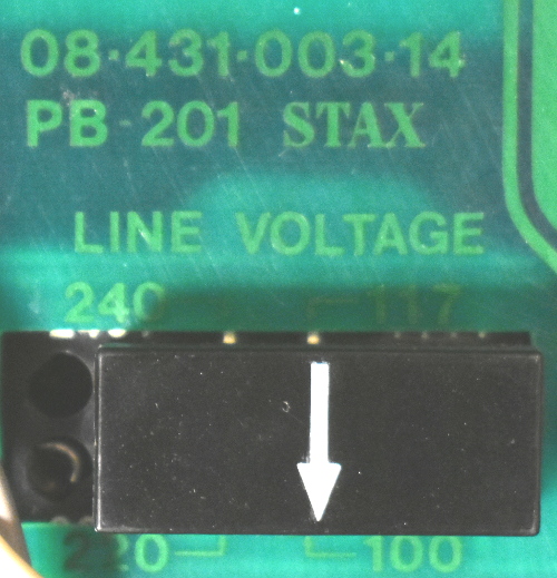
Thanks spritzer, I think I figured out what's beneath the 100V sticker by now even without removing it, just by looking at the manual... 😁 I wonder why Stax did that... Is it because the unit was meant for sale in Japan and therefore it was pointless to provide other voltage options, but at the same time to strip the voltage selection feature from the power supply was not worth it in terms of production cost (that is, it's cheaper to slap a tiny sticker on the back of units meant for sale in Japan than to produce units with two different power supply designs)? I understand why they kept the voltage jumper hidden under the bottom panel, though... I saw that in older SRM-T1 and SRM-T1S units this jumper was in the back (as thebrunx mentioned in his first reply above), but in this case at least a couple of the jumper slots are always exposed, which is dangerous, not to mention the possibility that the jumper may fall off or be kicked out by accident. A better solution would have been to hide the jumper behind a smaller panel, so you don't have to expose a lot of unrelated circuitry when changing voltage... I guess Stax decided to go cheap with this. I also find a bit amusing that, from all the things I asked in the OP, this is what caught people's attention... -
Hints on maintaining / improving my Stax SRM-T1S
plaurids replied to plaurids's topic in Headphone Amplification
Well, what do you know? It did have a voltage selection jumper behind the bottom panel... I hadn't bothered to check the first time due to the warning in the back panel, I'd inferred it would be a fool's errand. Moreover, the manual PDF doesn't describe how to reach the voltage selection jumper. Thanks thebrunx and spritzer! In due time: is it safe to change the jumper to (say) 117v and drop the step-down transformer for use with a 127V power outlet? Is changing the jumper enough, despite the warning at the back panel (it seems to be just a sticker on the metal back plate, but even so)? The manual says the unit has a 10% power voltage tolerance, so in my situation it seems safe to do as above, but I need to be sure.
-
Hints on maintaining / improving my Stax SRM-T1S
plaurids replied to plaurids's topic in Headphone Amplification
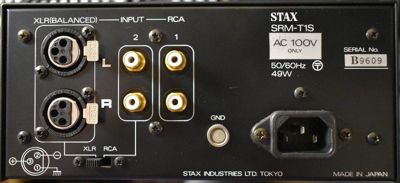
Thanks for the reply. Unfortunately, my SRM-T1S has no voltage change jumpers at all. The back panel clearly states "100V only" (50/60Hz). I wasn't expecting otherwise when I bought it (even though the manual PDF available on the internet describes a variant where voltage changes are indeed possible), so I bought the step-down transformer right after I ordered the unit. Good thing I did that... -
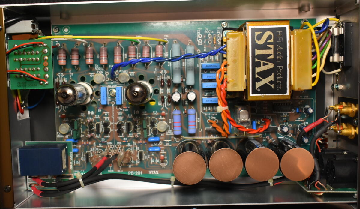
Hi y'all, Got my entry ticket into the Stax world in the beginning of 2018 with a Lambda Signature SR-407 earspeakers / SRM-T1S energizer combo. Got them from a Japanese seller and therefore I'm having to use a 100V step-down transformer for Japanese electronics here in Brazil (power outlets at home are 127V, 60 Hz). Only recently got the nerve to open the energizer to remove some dust and check the components (a bit scared of touching those big-ass 100 uF caps, but an anti-static brush and a lens cleaning blower sort of did the job). As far as I could see, all components seem original: The tubes are Gold Aero 6CG7's, Stax Signature selection. I understand that Gold Aero is not really a tube brand, but they rather select NOS tubes from various different brands. The only info I could get from the tube rear is that they are 6CG7's (not the equivalent 6FQ7) made in USA. (Edit) Comparing the remaining original lettering's shape in the tube rear with pictures from Ebay tube listings pointed to the tubes having in fact been made by Sylvania, most likely in the 1950's. For example, this 1956 6CG7 tube made by Sylvania for Zenith looks exactly the same (apart from the Zenith red print replaced in my case with the Gold Aero print, of course), particularly on the inside: https://www.ebay.ca/itm/1956-Sylvania-Zenith-6CG7-Test-NOS-Grey-Plates-Silver-Shield-Serious-Tubes-L398/174307174026 The tubes have grey plates with a silver center shield and a copper grid. The four, big 100 uF caps at the bottom right are Hitachi (CE W 85oC, 400V), but they baffle me somehow - the exact same cap brand / model looks very different in other people's SRM-T1S's pictures (usually black with aluminum / black top, unlike the bronze "unibody" ones in mine), so I wonder whether there is something special about them or if the different looks are only due to the period they were made. I've noticed that the Alps potentiometer is sometimes mounted in the opposite orientation elsewhere (with the PCB facing up instead of down as in mine). My listening so far showed nothing wrong with the combo (apart from a grounding issue - see 5. below) and I've really enjoyed the experience so far - my only previous contact with electrostatics was listening to Martin Logan ESL's, but the technology has always fascinated me. However, I worry about the long-term maintenance of the energizer, considering its age and my distance from the manufacturer, so I eventually need to learn to fix it myself. I may also consider modding the energizer in the future to improve it if it stops working properly. This leads me to the following questions: How do I identify tube / cap failure, apart from the glowing of the tubes? I have no experience at all in that (in due time: all 4 red LED's inside the energizer are glowing, including the one beneath the Alps potentiometer); Should I need to replace the tubes in the future, which brands are most recommended for my combo? I've seen several people here in the forum recommending prioritizing Japanese brands for a better match - how do they compare to my Gold Aero (Sylvania)s? Should I need to replace the electrolytic caps in the future, which brands are most recommended for my combo? Do I need to worry about the long-term wearing of other components (resistors, diodes, input MOSFETs)? Most likely due to the use of the step-down transformer and the fact that my apartment's power outlets are not grounded (sorry, old building), the energizer suffers from occasional humming when no signal is being fed (I use the balanced XLR inputs from a Fiio X7II DAP, which happens to have balanced output). Any ideas? Would modding the power supply help?