jokerman777
-
Posts
79 -
Joined
-
Last visited
Content Type
Profiles
Forums
Events
Everything posted by jokerman777
-
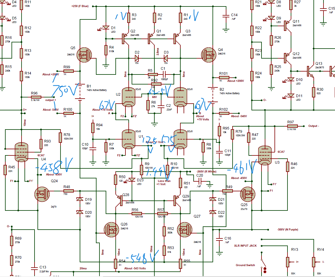
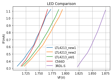
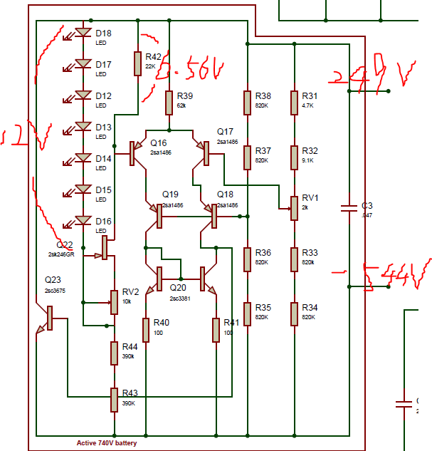
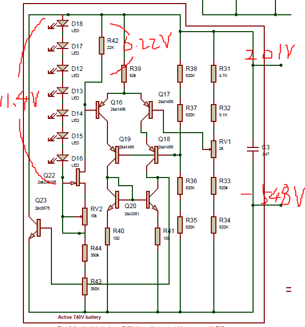
I went on and measured more things outside battery while setting battery voltage to 750V: Seems like everything is a little off. I suppose the key to get correct low offset at output is to get the output tube operating point in place (without considering the feedback shenanigans that I don't quite understand😵), with grid sitting on the -500V supply it should come down to getting the plate load CCS and cathode voltage in place. Other than the previously mentioned battery adjustment weirdness, measuring voltage across D1 and D23 I got 1.57V-1.67V, definitely on the low side similar to what I found in the battery. Also battery seems to be not outputing any current with little to no voltage drop across R99 and R100. LEDs With current noted on the schematic, at least for D1 and D23 they be running at about 0.5mA with a forward voltage drop of 1.8V (if all base current can be ignored). I took D1 and D23 and another one from the battery for a measure. LTL4213_old is taken off from the board, only plotting one as they all measured similarly, LTL4213_new is another batch I bought recently, along with the Cree C566D also a 2.1V red LED with nominal forward current of 20mA. These all measured pretty much the same, on the lower side of 1.8V but strangely never went down as low as around 1.6V as I measured in amp when operating. Only thing I can think of is derating due to the negative temperature coefficient? 3RDL-S is a 2.1V red LED with nominal forward current of 2mA, as expected the curve shifted to the right side. Seems to be a shot in the dark but I shall replace all LEDs with 3RDL-S and sufficiently elevate them from the board? (which I didn't do with the current LTL4213s on board..) 2SK246 I didn't take out the ones on board but gotten a few backup ones from ebay, hook them up on the breadboard and set voltage across 22K resistor to around 6.55V at 12V supply voltage from the bench. Then sweeping supply voltage nothing surprising and they regulates fine... Resistors I replaced R33, R34, R43, R44 with 500V rated resistors - as I just realized voltage across them will always be a little above 350V, and this doesn't change anything. So I think I'm going to replace all the LEDs this weekend, although it seems everyone else are using LTL4213 just fine, possibly still not the cause of my problem...

-
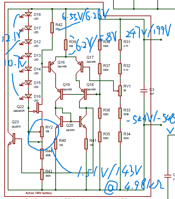
This is really helpful, thank you so much! I'm way too ignorant on this so I wanna verify if I understand things correctly. More probing around the battery with Vgs on 2SK246 now, "/" is before and after trimming RV1 to bring down battery voltage to around 740V. So in theory assume base current of Q16 is negligible, while the regulation on the LED string is not ideal, Q22 shall work as a current source fine despite the Vds drop from 4V to ~2.65V, that means regardless the LED is not the source of my problem right? Now the current running thru R42 before and after are 298uA/284uA, current thru RV2 before and after are 303uA/287uA, while not super accurate but it seems the base current of Q16 is on order of magnitude of a few uA and had changed about 2uA, this can cause Vgs of Q22 to change about some tens of mV depending on RV2 value, enough to say that whatever Q16 is doing here, it's effect on the CCS is indeed negligible? That lead to the conclusion the first thing I should do is replace the 2sk246 right? And breadboard test them with a bench supply varying input voltage around 10-12V with R42 and RV2 in place. Is there a recommendation on readily available replacement of this part? Thanks again! 🙂
-
Many thanks @simmconn! Things I know so far: PSU voltages sits still as I tried to trim the batteries closer to 740V, none is loaded down. Also unlikely that I'm running on the boundary of current limiting because I trimmed one channel at a time while leaving another channel with batteries not conducting? monitoring total power consumption it is 30-40W lower than bringing both channels to be on. All resistors seems fine, no visible damage and ones below 100kohm I can measure on board and values are correct. Measured two C3675s in same channel on board with toy tester, hfe are both around 48 When I set RV1 to R32 side, I can comfortably set voltage across R42 to 6.55V, this is what I get: Then I leave RV2 alone and turn RV1 to reduce positive voltage to ~200V, I got: I remember reading somewhere that LEDs need to be 2.1V, mine with handheld meter all measured around 1.7V, but I guess around below 1ma bias current in circuit this sounds about right? I unfortunately don't have any spare k246, best I can do is pop one out and find replacement if they are malfunctioning. Gonna measure more nodes over the wknd
-
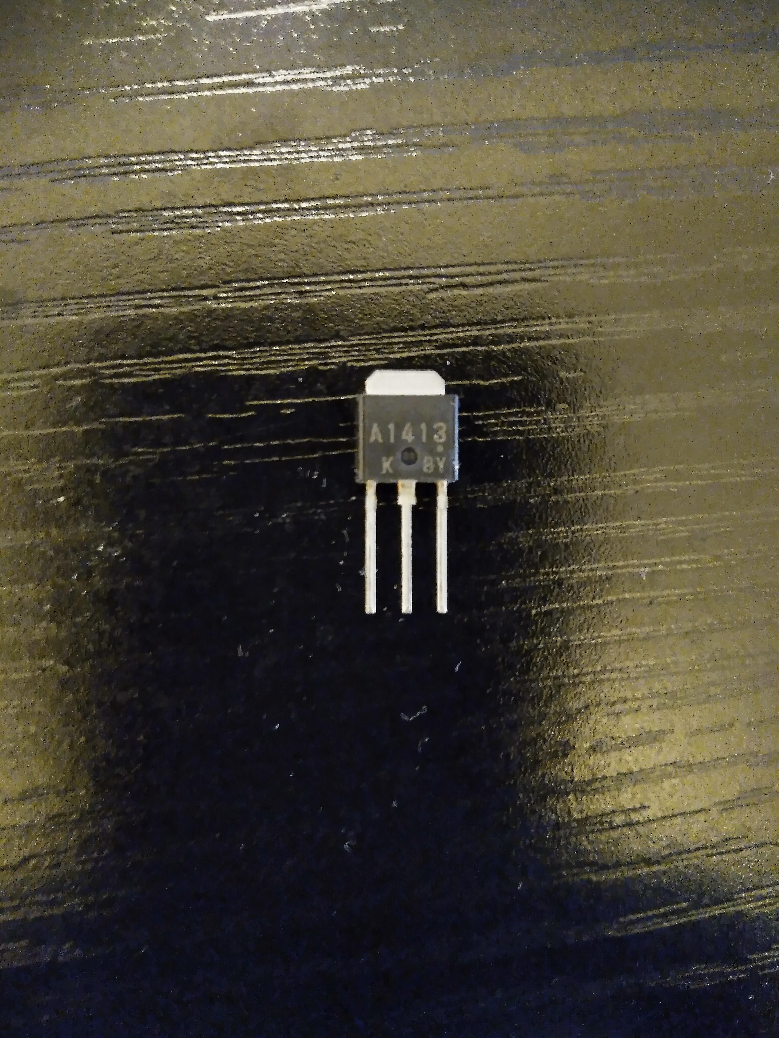
Mine from Bdent looks like this. If anything my batch of 1413 are labelled as "K" grade and my batch of 1627 are labelled as "L" grade, on my toy transistor tester from Amazon the hfe measures are 100 and 60 respectively which kinda checks out. From my mouser list all resistors are rated 350V, 0.5 watt, most are Xicon except a few. I will double check on board resistor values from color code tonight though. 🙂
-
Q16-Q19 are 2sa1413, I also have a bunch of 2sa1627 as well, least both of their datasheet looks like a straight copy and paste from A1486 datasheet. Q23 is 2sc3675. I believe they are all genuine from reliable sources.
-
😑Right channel is exactly the same story - negative voltage likes to bounce back from - 544V to -549V and stay when trimming RV2, with RV1 bringing positive voltage down output offset just keep increasing, and is -125V/-151V near -549V/200V I found one thing though - if I start off setting RV1 wiper to the upper R32 (9.1k) side, trimming RV2 I can easily set 6.55V across the R42 independently and they stay there, until I trim RV1 to bring down the positive voltage, they drift to something else between 6.2V-6.6V. This happens to all 4 batteries.
-
thx, I will do that in the next few days (I remember last time I tried the behavior was similar). When I do that should I leave left channel in this current state?
-
Thanks for the help! Yes I only used RV1 to adjust positive battery voltage after trying to set voltage across R42. And yes I can set overall battery voltages to 740V too: because the negative voltage is just staying there at -549V I just keep further trimming RV1 to bring down another 10V on positive voltage, that gives both battery voltage -549V/191V. Now output offset just increase to L- = -123V and L+ = -150V, measure R42 again it's 6.35V and 6.6V
-
I just gave my best shot on left channel, don't know if it's normal at all but setting voltage across R42 isn't easy, when either voltage is below 7V trimming the pot don't make them go down continuously and they like to jump down a few hundred mV and hanging around there. Also trimming either pots affect both voltages across R42s and in general seems like they like to stay on different side of 6.55V. So the best I got is I got both stay between 6.5-6.6V, this is when battery voltages are: 216V/-542V and 231V/-547V Starting from there I use RV1 to bring down the positive voltage and it ended up at: 200V/-548V and 200V/-549V Remeasuring voltage across R42 they be what they wanted to be: 6.3V/6.7V Output offset is L+ = -103V and L- = -135V Also there is likely some oscillation going on in this state as I can hear the output tube squeaking. is setting voltage across R42 not suppose to be this hard and trimming RV2 can continuously bring it from 7V down to 6.55V and they will comfortably stay around there?
-
Thanks! So to elaborate none of the things I measured are bouncing themselves all over the place when leaving the pots alone. Output DC offset simply follows battery voltage and goes + -> 0 -> - as I trim the pot but only likes -543V/245V with the lowest offset near 0. As for voltages across R42 - they start off well above 7V when battery is not conducting. Trimming RV2 will continuously reduce this voltage, until I get to around 6.8-7V ( which is also the -543V/245V; 0 offset point) then there seems to be a discontinuity where further trimming the pot will make it jump to around 6.3V. Only back and forth trimming both batteries I can sort of get 6.4V and 6.6V, it almost seems like V R42 really doesn't want to go to 6.55V specifically. Oscillation yes definitely happens as turning the pot makes all kinds of squeaking noise coming in and out from the tubes. I'm assuming batteries from the 2 channels are independent as they only share the PSU, so I only tried to bring batteries in one channel to conduction at a time. I guess another way to look at it is, is it normal that when both batteries are conducting, I can never trim the negative voltage below -543V? Passing that point it just likes to go back up towards -549V and stay there.
-
😵 Spend the last few days trying to adjust the battery and no luck I first tried the method of setting voltage across R42 to 6.55V, keeping RV1 centered and adjust RV2. As I slowly bring things into conduction, voltage across R42 starts slowly decreasing till it get to around 6.8V then it starts jump around 6.55V, as I adjust both RV2 back and forth, the voltage across the resistors seems always likes to stay a few hundred mV apart around 6.55V, and the best I can do is something like 6.4V and 6.6V. In this case negative battery voltage stays at -548V, while I can adjust RV1 to bring positive voltage to ~200V, output DC is wild (somewhere around 80 to 130V) and no small adjustment can bring it close to 0, only can be reduced by bringing positive voltage back up from 200V with either pot. -------------------- I then reset all the pots back to center position and check the overall behavior. When first power up batteries are not conducting with many of the LEDs not lighting up. output voltage is simply 250V/-560V. While keep RV1 (2k) centered, turning RV2 (10k) I get the following behavior (time aligned): Negative voltage: -560V -> -543V ->-549V (stays) Positive voltage: 250V -> 245V -> keep decreasing offset: both positive -> closest to 0 (<+-3V) -> keep increasing as negative voltage (~-100V as + voltage approaches 200V). RV1 didn't really do much IMO, I can use it to trim down positive voltage too just way less change per turn and offset behaves the same as when I turn RV2 to do it. So offset wise it really likes -543V/245V the best and trimming it any closer to 740V it just keep getting worse in negative direction. I measured R42 voltage in this condition and it's 6.9V/7V, which makes sense bc below these values it starts jumping around 6.55V as I observed previously. I did this measure on left channel but I briefly tried right channel as well and it seems to have similar behavior, so likely I made the same mistake in both channels. I feel the servo is working as +/- output offset follows each other closely as long as neither is too wild (>100V). Parts I used are 2sa1413/ksa1156 for 2sa1486s on board and on heatsinks respectively, tubes are supposedly matched JJ E88CC and new production Mullard EL34. Is there any insight on what could be the problem or how to track it down? Many thanks!
-
So I'm trying to adjust batteries on one channel for now, and was trying to follow Kerry's method. I can set the voltage across the two 22k resistors to be around 6.5V by turning the 10k pot fine, but then it seems turning the 2k pot only affect the positive (~200V) battery voltages and the negative voltage sits still at -548V. I tried turning away the 10k pot a little bit too and neither does it seem to affect the negative voltage but it does change the positive as well, so for now I can have +200V/-548V for this channel. All LEDs in this channel currently light up fine, but weirdly sticking probes across the 22k resistor can dim the some LEDs and cause some squeak noise on the tubes.. Is this behavior expected at all that I shall just move on and adjust the rest or does it look like something is off?
-
That's what I was told by Bud when I contact them to buy something yesterday. Possibly if you want something in large quantity you can reach out and maybe get a discount over the listed price.
-
thanks! Never thought of this obvious option, not so resourceful I am : )
-
Found the rs export site here: https://export.rsdelivers.com/?fromAmericas=1 But when I enter US as the destination country they redirect me to the US site with "Due to local tax laws we request that you place your order with our US website". dk why this is so difficult in 2023 😃 btw I was told bdent is going to close down in Oct, so maybe last call for something.
-
Hard to find FQP8N80C replacement now as it's experiencing some long lead time. I bought off the 3pcs stock of FQPF8N80C from bdent, and also have ~10pcs of STP8NK80ZFP I bought originally as backup plan, both comes with isolated package and has lower overall power consumption rating. On the surface for now I only need one to fix the +500V/bias supply first, I'm inclined to just use STP8NK80ZFP as I have a slight OCD of if replacing one works I want to replace the other 3 too.... I had success using these in the KGSSHV PSU, or is there good reasons that I shall stick with the Fairchild FQP device?
-
I had previously considered ultrasonic cleaner for the boards but curious would it mess up with the thermal paste applied? Anyway good luck and hope everything will work out fine! 🙂
-
Thanks for the suggestion yeah I will probe the voltage drop across them next time I probe the resistors. maybe the line voltage plays a role here too? My trafo primaries are spec'ed at 115V and I believe my mains is above 120V on average, also need to check out how accurate that power measurement thingy is that I borrowed from my friend.
-
Thanks, it seems my PSU consume twice amount of power as yours.. powering up only all negative rails it's already 22W, adding +250V it becomes 33W so I expect when I get +500V/bias working it will be 40~50W The exploded 10m90s were Q2 and Q3 (Q1 was unknown). I think the shorted D3 is the cause of Q3's death, as for Q2 I don't know exactly yet, possibly the FQP8N80C (Q4) is also dead from the first time failure due to shorting of Q1.
-
I just went through a couple more rounds of PSU trouble shooting. First time replaced 4 10m90s in the +500V/bias supply where short to bracket happened to one of them, I admit I didn't measure other components other than rectifier diodes, power on and 2 of the 10m90s exploded. (before explosion I was measuring bias voltage and it reads fine) Took it apart and measured more things - D3 zener was dead to short, didn't know if it's the cause or the consequence of somethings else. I replaced all 10m90s again plus the dead zener, op27 and ref102, leaving the hard to source C3675 and FQP8N80C in question. Power on with no load again while monitoring power consumption - in-rush reaches 200W and didn't drop within a short period as I expect it to so I quickly shut it off, something smells funny too. In both rounds I powered on all other supplies individually beforehand and output measured fine. I think I'm going to take it apart again and measure more thoroughly including all the resistors and likely will try just replace all the semiconductors in that rail once I find the harder to get replacement parts. I know it's not the right way to test a device but I measured D-S resistances of the fqp8n80 in circuit and it gives me a stable ~6Mohm which is different from the same device measured in other rails, so something is funky around there. more dummy questions: Is passing forward bias test enough to say that zener diodes are fine? As I was monitoring power consumption of the PSU with no load, each HV rail seems to consume about 10W when stabilized, is that more or less expected? my transformer still lightly buzzes.
-
Wanted to buy some FQPF8N80C seems uk rs-online only let me enter UK address, is there a way to get them ship worldwide?
-
Thanks for the all the explanations and the pic! For grounding I wasn't talking about connecting PE and signal ground again in the amp box, ik they should only meet once whether through a breaker or not no matter how many boxes of an amp. I was trying to understand why it's better that they met in the PSU box instead of meeting in the amp box at signal ground, I don't have good reasoning for the later other than I did it that way in single box amp and in my imagination the former extended ground loop between source and amp by the length of umbilical. I will do the former with the advice given, just purely curious, and maybe it doesn't really matter all that much between the two 🙂 In terms of Kevin's pic, I saw a resistor lead coming out of one of the circuit ground terminal block, wasn't clear where it goes to but based on what George said I suppose it goes to rear standoff slot which connected to the chassis, then returned to IEC earth as well as pass to amp box as chassis ground. Idk if it's bc my board is a newer version or not - the pad on that standoff drillout hole is already connected to the on board circuit ground, seems like I just need to put the standoff back there and make sure it's also connected to the chassis I'm all good? rest will be what I already have here: IEC earth, chassis, magnetic shields, output to umbilical. Good point! Craig described the same to me in an earlier post that why I picked this insulation washer based on the length of its neck. I will double check when I re-mount everything 🙂
-
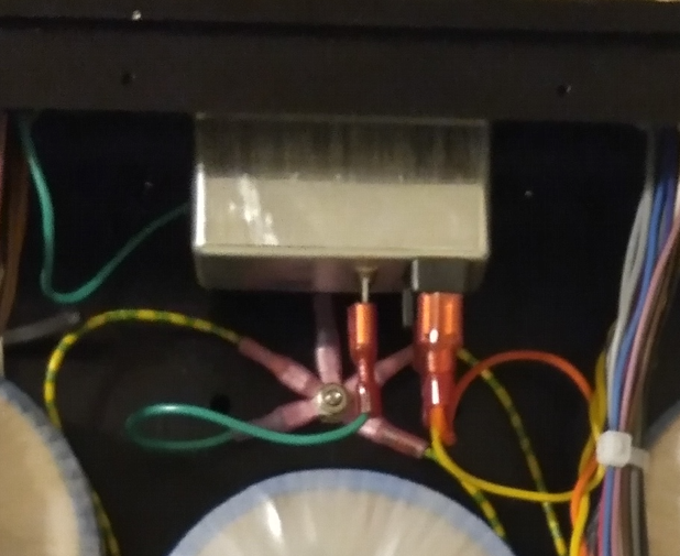
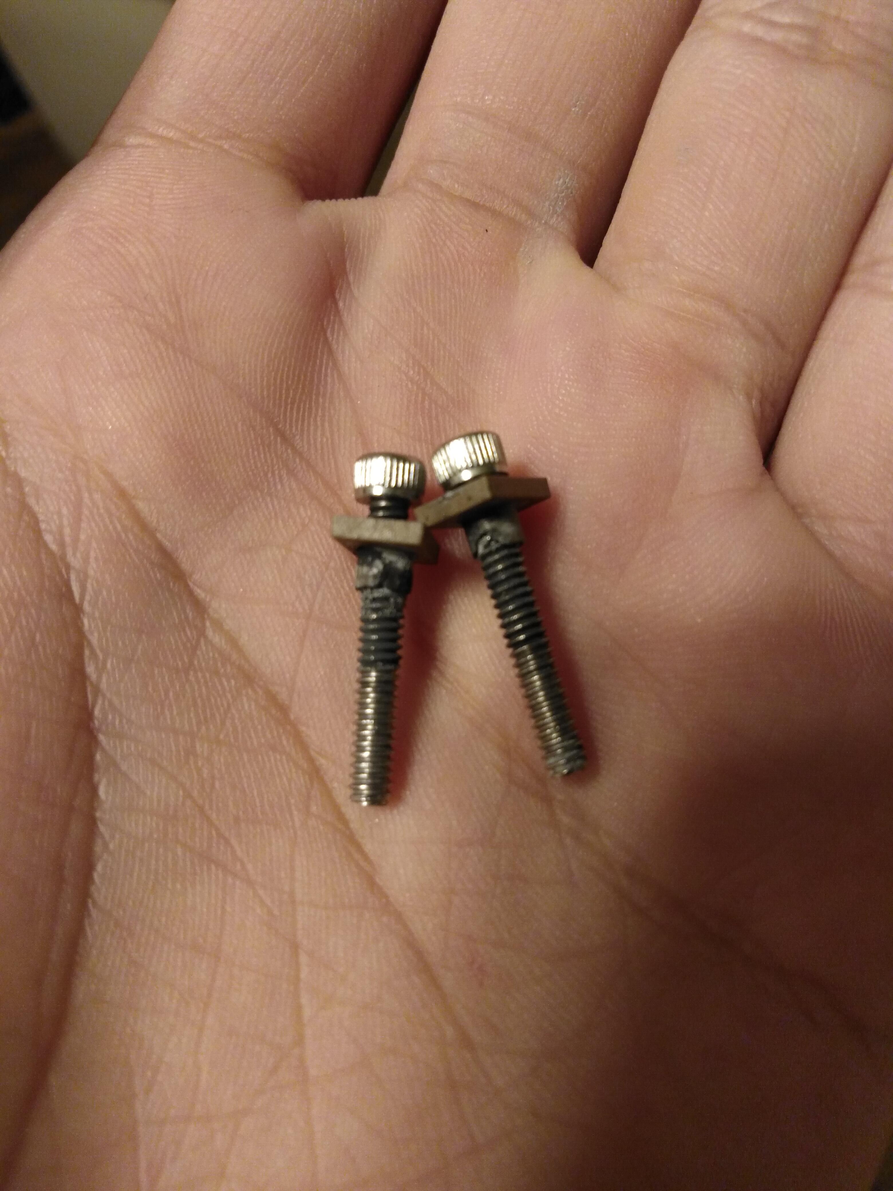
As for torque I gotten a torque screwdriver and copied homework from one of the early post here and set it to 0.82Nm Sounds good, I will re-inspect all the mountings on the brackets I think I also do have a slight misalignment between the brackets and the semiconductor pins
-
Thermal compound I used this: https://www.amazon.com/dp/B09VDLH5M6?psc=1&ref=ppx_yo2ov_dt_b_product_details I believe pretty generic kind for CPU mounting in PC. For those 4/40 screws yeah fitting is probably marginally fine, most of them slide in and out of the 7721 freely, some minority samples I feel resistance try to slide them in and I don't use those, I suppose excessive thermal compound filling the gap doesn't help neither.. What did you suggest that could potentially be the cause of trafo buzz? I'd think it's not bc of shorting since over the wknd everything was fine with no shorting and I still heard a buzz. (my trafos are at smaller size and I was given a VA rating of 84, I think SumR/toroidy uses 100VA rated bigger core). Thx!
-
I took the PSU apart today for simple checkups. On the positive supply side it was the case of 7812 and Q3 10m90s both shorted to the bracket, burning up the insulation. I think I initially had applied force to drive the screws incorrectly such that they bite into the insulation washer and damaged it. They been measuring fine for shorts until I mount the board into chassis and heatsinks and also move it around which probably eventually break the limit. Diodes all measured fine after eliminating shorts but I also ordered 512s for backup. Think I'm going to replace all the 10m90s at the 500V/bias rail later on and see how it goes. Still don't know what was with the spark on the other side of the board.