jokerman777
-
Posts
79 -
Joined
-
Last visited
Content Type
Profiles
Forums
Events
Everything posted by jokerman777
-
Mind explain why it should be this way? My naive thought was in the case of single box amp, source and amp have their circuit/signal ground connected at signal input jack of the amp and then both meets mains earth in their own box, thus having amp circuit ground meeting earth at input jack minimizes the ground loop between amp and source, for two box T2 if earth meets circuit ground within the PSU box this ground loop would be extended by the umbilical cable?
-
Thanks for the suggestions! I will take it apart and do connectivity & diode test first, then maybe reconnect rails one by one for measure. 7812 the case is ground pin so if that's shorted to the bracket it will short signal ground to chassis ground and circuit will still work, this is the only reason I can think of rn that can short the two GNDs. Negative rails was working fine until I see the spark which happened on the negative supply side so I'm not sure now, something might have gone up to smoke. great tip that if I have one leg of the rails working I can use it as reference 🙂
-
Oh I got parts referencing a BOM where it says stth1512D that is obsolete and I used STTH15S12D instead, I suppose not going to make a difference?
-
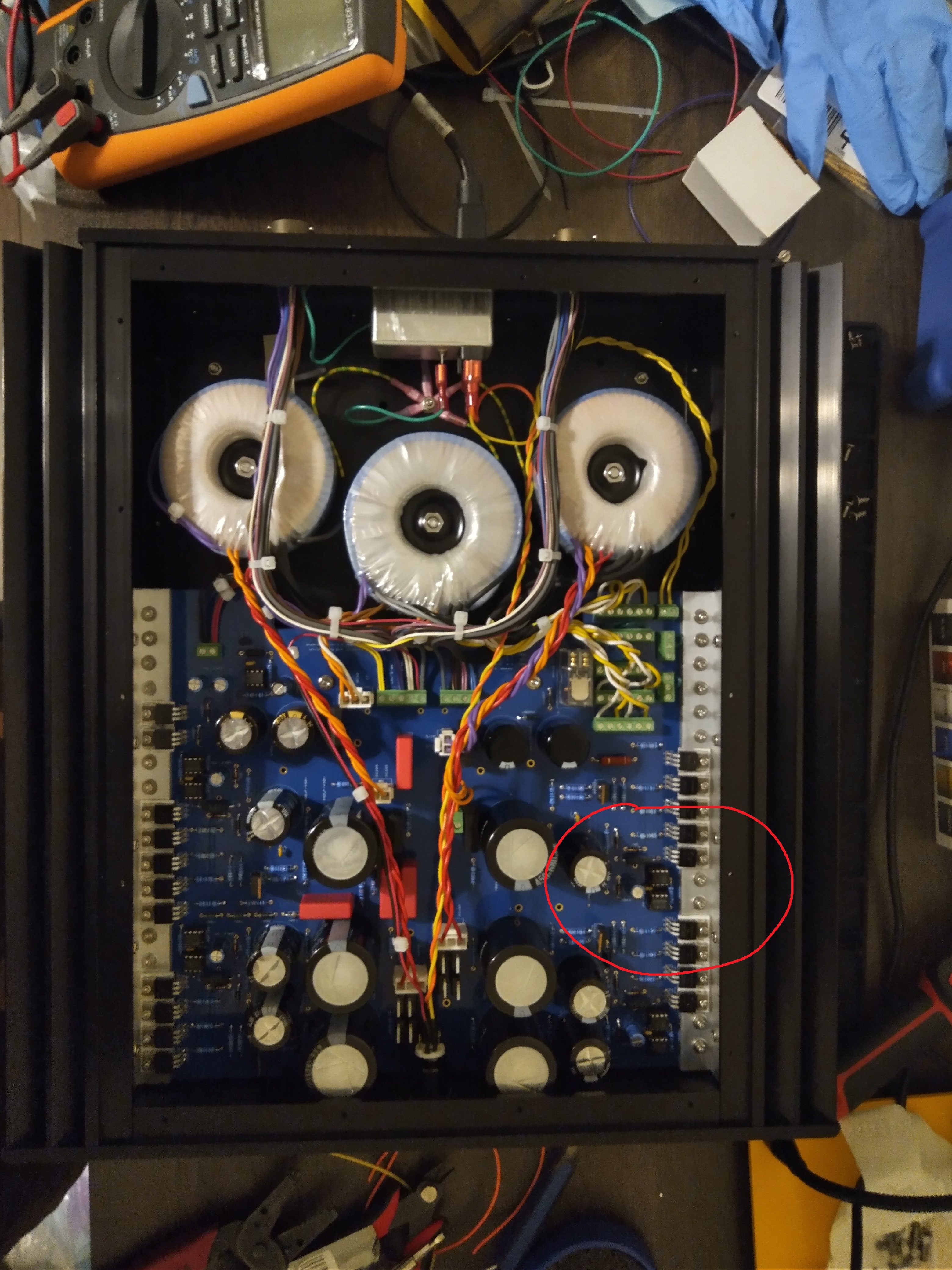
Thank you both for the input! Yes I thought of if chassis/earth ground need to meet signal ground best place would probably be at the signal input, so for now in the PSU Chassis I leave signal GND floating and mains earth/chassis gnd/transformer shields meets at one point and then will be passed to amp chassis ground via umbilical. ------------------------------------- So yesterday I put the PSU together, did connectivity test for shorts and then power on with no load, all output voltages measures fine. Today I thought I want to mount the power transformer tighter to see if it helps with HV transformer buzz so I replaced bolts with longer ones and added lock washer. Power on again with no load (and I didn't do connectivity test as I assume things were same as yesterday), everything was fine until I done measuring the negative voltages and about to go measure the positive voltages, something suddenly sparkled (in the area of the red circle in the picture, too fast I didn't catch which component) and then a bad smell came out, I powered it off right away and nothing looks burnt visually for now. Things I know so far: -Chassis/earth ground is now shorted to on board signal ground, either through the case of 7812 or I might have a short somewhere else. -The anodes of the 10m90s at the +500V/Bias supply side are shorted to gnd, so either one or more of these might have the case shorted to the bracket or I have dead diodes causing it. -On the other side where the sparkle happens the cases of all the transistors are not shorted to the bracket. -Disconnecting the HV trafos power on again +-12V supply still works I know this is way too little information to find out what went wrong other than I have one or more things shorted, I will take it apart further inspect this wknd When testing without load is it ok to run the PSU without heatsinks installed? As that will save quite some effort since I likely need to do multiple iterations of trouble shooting.

-
Should signal ground meet chassis/earth ground in the PSU box? I found that the center stand-off pad near the output terminals on the PSU board is connected to PSU board circuit ground and mounting a standoff there will make the chassis gnd to signal gnd connection, otherwise the two grounds will be separated in both boxes. I found Kevin's old post in this thread mentioning "everything floats" so should I leave out this stand-off?
-
I just got the crimping contact version of the connectors earlier this week. Yeah the tools are very expensive, gotten some rusty secondhand one from ebay and hope it will work out... All that is just bc I'm pretty sure I don't want to deal with soldering 8*14 closely spaced soldering cups while also worry about insulation 😅
-
don't know about anything else but the BIAS is probably fine, measuring after 5M resistor the finite impedance of the voltmeter forms a voltage divider with it.
-
hmm I've gotten ceramic straight pin tube sockets from thetubestore and turns out the 8pin octal ones don't fit the board. Are these from diy hifi supply the right ones to get? https://diyhifisupply.com/tube-sockets/premium-teflon-sockets/ Searched older posts where Kevin mentioned which ones to get but links are all expired.
-
Thanks! I got the ones with 0.79mm extension according to a bom posted in an earlier thread here, I guess that's too short to cover TO-220 pads with varies thickness. I will get another batch with longer extension. Actually why is it bad for the extension to protrude the isolation pad? Assuming it's not so long that it will also protrude the metal bracket and board underneath. With that in mind seems like the 7721-10PPSG from the datasheet is a good fit with 2.41mm extension going thru entire TO-220 pads and about half way into the isolation pad.
-
Thanks for the tips Craig! Metal screws + shoulder washers + thermal compound it is then, no more fooling around. Will for sure check if the length of the shoulder washer from the other side for each installation. 🙂
-
Hi, back with a load of dummy questions in the midst of building it 🙂 (Again I got the boards and chassis from GeorgeP which I believe are same as Kevin's original design). PSU Front Panel Power Indicator: There is a circular cutout in the center of the PSU front panel, I measured and diameter is roughly 19mm, any recommendation on what part to use here? I suppose it will be a switched light, although the IEC inlet is already switched? I think I found some push button with LED on parts express that should fit. Grounding: If I'm understanding the layout correctly, I believe mains earth/XLR input ground/Amp chassis are connected together as chassis ground, and can be connected to the circuit ground via the on board switch. It seems like the PSU chassis is not grounded? Also there are two GND output pads (electrically connected on board) on the PSU board and multiple GND pads on the AMP board, is it recommended to or not to pass both GND output points from PSU to the amp? don't how much it matters but passing both sounds like ground loop to me. Transistors Mounting: With AAVID 4171G thermaloy can I get away with not applying thermal grease? Anyone has the success of using nylon screws for mounting the transistors? I got a bunch of them and thought they will give me a peace of mind when it comes to insulation but second thought they are not as mechanically stable as metal ones. Components placement: On the amp board I figured these are probably better to be soldered on the back of the board (facing top): LEDs, power resistors, trimmers and test points, are there any other components that might run warm which are better to be soldered on the back? Thanks in advance for your opinions!
-
Thanks for the info! Yes I used Toroid Inc once a few years back and I think it was very pricy for what I asked for - I think their one-off pricing is based on designing and making initial prototypes for businesses, which is understandable. I been using Antek whenever something off-the-shelf fits the need, unfortunately just not for a T2. Guess I will reach out to toroidy and mueller-rondo in EU for a quote then. Tricky part is I already got the chassis and I think Kevin designed them for the SumR ones originally where the diameter of each trafo can't really exceed 3.6", probably pretty marginal for their ratings and I'd need to spec that too, this might further reduce my options. (no lundahl, EI, C core etc..) btw I contacted Toroidy once for something else and I got the impression that they don't have 115V or dual primary winding trafos in stock in general.
-
That's unfortunate.. I been planning on getting a set of power transformers for T2 build from SumR. Any recommendation on other good winders within North America who'd do custom one-off toroids? Other alternatives I heard mostly are from EU, prefer not to get heavy irons from overseas unless running out of options....
-
🙂Got the amp finished and running fine for more than a week by now, finally got to experience some ES setup. Many thanks for all the helpful advices I received here and there on the forum, thanks to KG for the great design and also Birgir who spent extra time clarifying a lot of my confusions in addition to supplying the partial kit. For offset I ended up paralleling a couple of 10K resistors on the back of the board to the R in series with the trimmer, and with that I'm able to trim the offset down around 0. For the currently back-ordered parts: I used STP8NK80ZFP instead of FQP8N80C, and 5027 instead of 5026MOS and it has been working fine. 5027 has higher capacitance but I suppose it matters less when it's only used in the PS regulator here.
-
Thanks, it shows back-ordered again on the UK site now, back to living with 5027s
-
Tried to order some but seems like they don't deliver to US address 😑
-
I finally gotten it put together and powered it on for adjustment, high and low supply voltages are fine and all LEDs lights up. I observe the following however: -The balance adjustment I can get it drift around 0V but likely only down to the accuracy of +-0.XV at best -The offset adjustment I can only trim the pot all the way down and get +25V and +35V on each channel, it won’t go lower and seems to be slowly drifting upwards over time. -Bias TP measures 600V instead of 580V (I can maybe try other zeners to adjust this) I built it with A1968 CCS, testing is done without headphone plugged in nor is servo connected, unit was on for about 30mins when doing measurement. I suppose at least this DC offset suggests I'm doing something wrong here? I cannot trim it around zero and nowhere near. Also before any adjustment I checked that all the pots are in middle position, when I turn the amp on the first time DC offsets are as high as 150V - was that an extreme value for the offset pot? Edit: msged Birgir and was told changing the resistor value in series with the offset pot should do it and rest is fine, sorry for dumb questions bombing
-
Thanks! I will give them a try and report back, tho won't be able to find out till after a good while. 😀
-
Hi, I'm slowly sourcing parts for a T2 build and wondering if 2SA1627 will be a fine replacement for the 2SA1486s that are not mounting to the heatsinks (those I will just use KSA1156)? Seems to have mostly the same ratings other than only 1W of maximum dissipation, would make my life easier if it works comparing to using the SMD STN9360... Thanks! 🙂
-
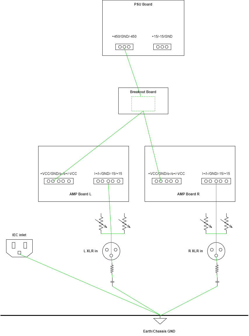
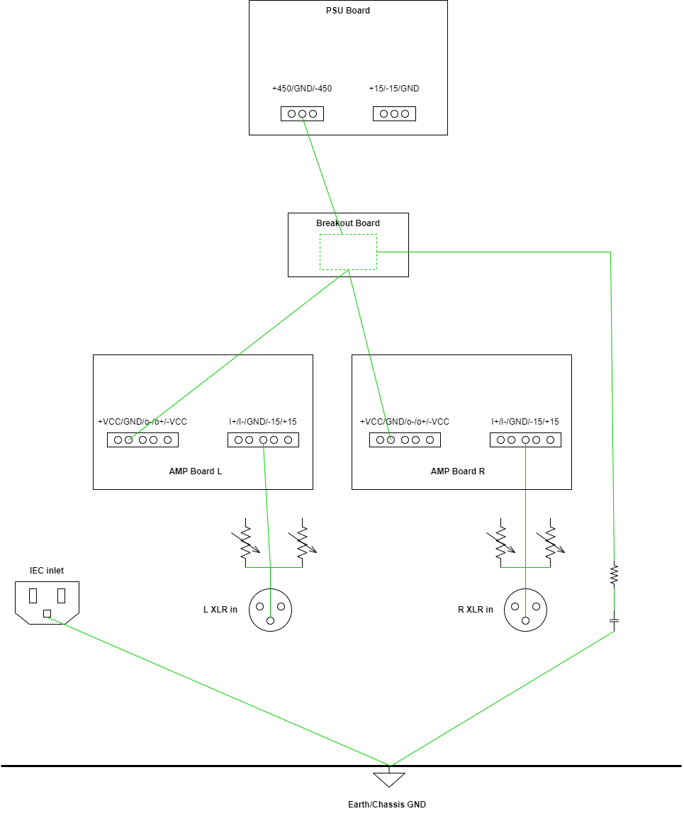
I was doing a little bit of layout planning on my KGSSHV build and have this newbie question about grounding.. I will be building it out of the partial kit from Mjolnir audio, the on-board heatsink version with 450V rails, other than the original PCB set I think I'm also going to make a small breakout board to distribute power from the PSU board to the two amp boards. I have the following 2 grounding configurations in mind and wonder which one is better? Config A both the input signal ground from the XLR jacks immediately return to earth ground, then they meet again on the breakout board. Config B the input signal grounds keep separated until they met on the breakout board then return to earth ground from there. In my mind config A has the shortest ground loop between the source and the amp; Config B however is more of what star grounding is like? Any input or suggestion much appreciated 🙂 Grounding A: Grounding B:
-
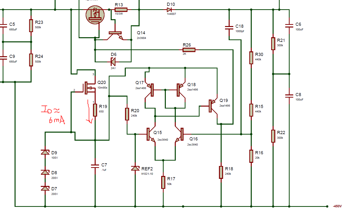
Very helpful info, thanks Simmconn! I was searching for high voltage depletion mode MOSFET and IXTP01N100D indeed came to the map. I kinda do want to get the amp running before the of expected shipping date of those transistors which takes months. Been sitting on a pair of X9000s that I can't listen to without an amp for a good while now. I don't know if I'm doing this correctly I took a rough guess of the current running thru the 10m90s based on its datasheet. And seems to use IXTP01N100D for replacement I should find the Vgs that gives the same Id and then get the Rk value from Vgs/Id? Tho the figure in the datasheet doesn't have the resolution for this application 😵
-
Thanks, looking at the datasheet I think the KSC5027 jamesmking suggested might be a better fit and pretty legit replacement for KSC5026M? the specs looks like they are the same thing other than the 5027 can handle more dissipation (I only know how to read numbers so I can be dead wrong). TO-220 should fit into the TO-126 footprint, base and emitter pin are swapped so just need to flip it when soldering it in? I'm also curious what makes the 10M90S special to be a current regulator IC? The datasheet label the pins as G/A/K (gate, anode, cathode?), is it basically a MOSFET?
-
TKD 4CP-601 & 4CP-2500 4-gang volume pot and PCB GB
jokerman777 replied to mwl168's topic in Do It Yourself
ohh my bad I mean the pads for the 4CP-601 not the 2500. But cutting your 4 gang board is a good idea too, thanks! -
TKD 4CP-601 & 4CP-2500 4-gang volume pot and PCB GB
jokerman777 replied to mwl168's topic in Do It Yourself
Hi Pars, wonder what pad size do you use for the 4CP? I'm going to make a board for 2CP. Thanks! 🙂 -
Thanks for the advice! My mouser updates tell me that (which is probably not new info): STN9360 a batch of production is done and is on the way to warehouse now so I guess they will be back in stock soonish. 10M90S says production in process so despite long wait time probably will come back. KSC5026M it says "Production Issues Reported - Delivery Unknown" which doesn't look good 😅 I wonder if I can do 2SC3840 instead? it's in the PSU and for no reason and understanding I thought I need to either use 2SC3840/2SA1486 or KSC5026M/KSA1156 in complimentary pairs... but since 2SC3840/KSA1156 is what I can get realistically... btw I think I'm going to use STP8NK80ZFP instead of the obsolete FQPF8N80C, at a glance the specs looks very similar other than a different Id rating and speed.