stv1756
-
Posts
18 -
Joined
-
Last visited
Content Type
Profiles
Forums
Events
Everything posted by stv1756
-

Kerry Design mini GRHV\GRLV and JoaMat mini T2 Group Buy
stv1756 replied to mwl168's topic in Do It Yourself
Received. Many thanks! -
Kerry Design mini GRHV\GRLV and JoaMat mini T2 Group Buy
stv1756 replied to mwl168's topic in Do It Yourself
Payment sent for blubliss. Thank you! -
Boards received. Thanks! Much appreciated.
-
CLOSED: Alpha/Song Huei Potentiometer Group Buy and TKD Attenuators
stv1756 replied to cspirou's topic in Do It Yourself
Payment sent. PP address is good. Thank you! -
CLOSED: Alpha/Song Huei Potentiometer Group Buy and TKD Attenuators
stv1756 replied to cspirou's topic in Do It Yourself
Sent $$$ for fees. Thanks! -
CLOSED: Alpha/Song Huei Potentiometer Group Buy and TKD Attenuators
stv1756 replied to cspirou's topic in Do It Yourself
Paid. Thank you! -
CLOSED: Alpha/Song Huei Potentiometer Group Buy and TKD Attenuators
stv1756 replied to cspirou's topic in Do It Yourself
I'd like 4 Alphas, Thanks -
Payment sent for extra GRLV boards. Thanks Soren!
-
Payment sent. Thanks sorenb!
-
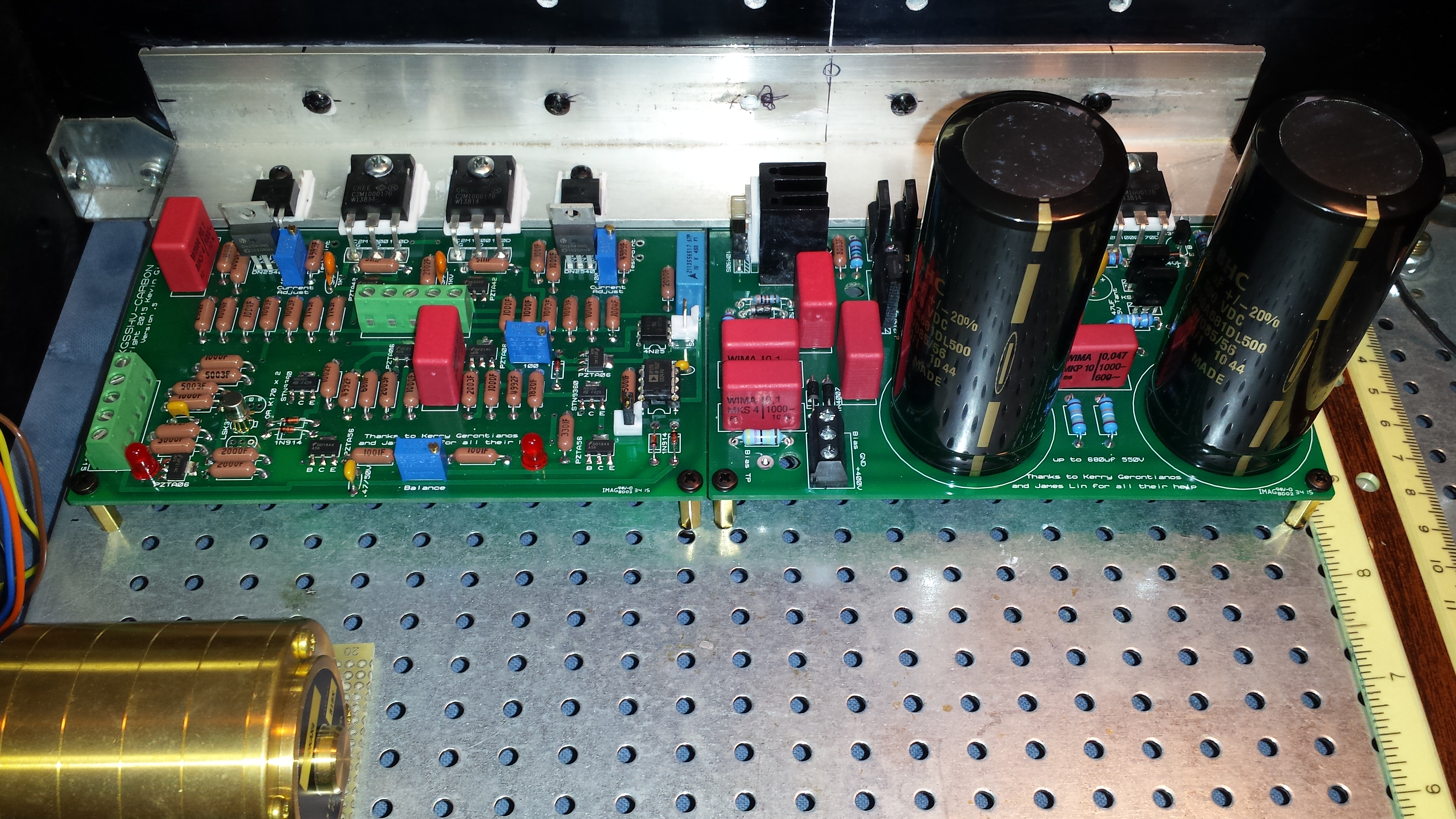
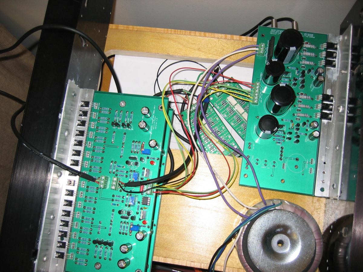
We ordered from the BOMs that were first posted. Everything was good except the 4700uf caps for the 15v PS need to be 16mm dia with 7.5mm lead spacing. Also as mentioned above, to get to 20ma (1v across the testpoints) you will need to lower the 182 ohm resistor by the offset pot to 120 ohm. Amp been running for 3 hours without any issues. Initial impressions? Reminds me of the T2! Many thanks to Kevin, Brigir, Michael and others for an outstanding design and for putting this group buy together. Photo is from yesterday before installing the transformer and the wiring.

-
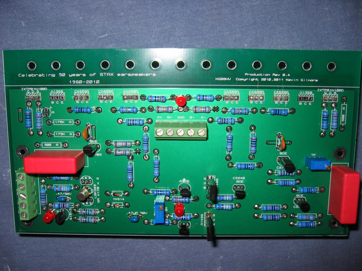
Here are the pictures of Andy's board.
-
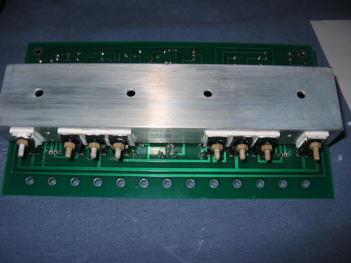
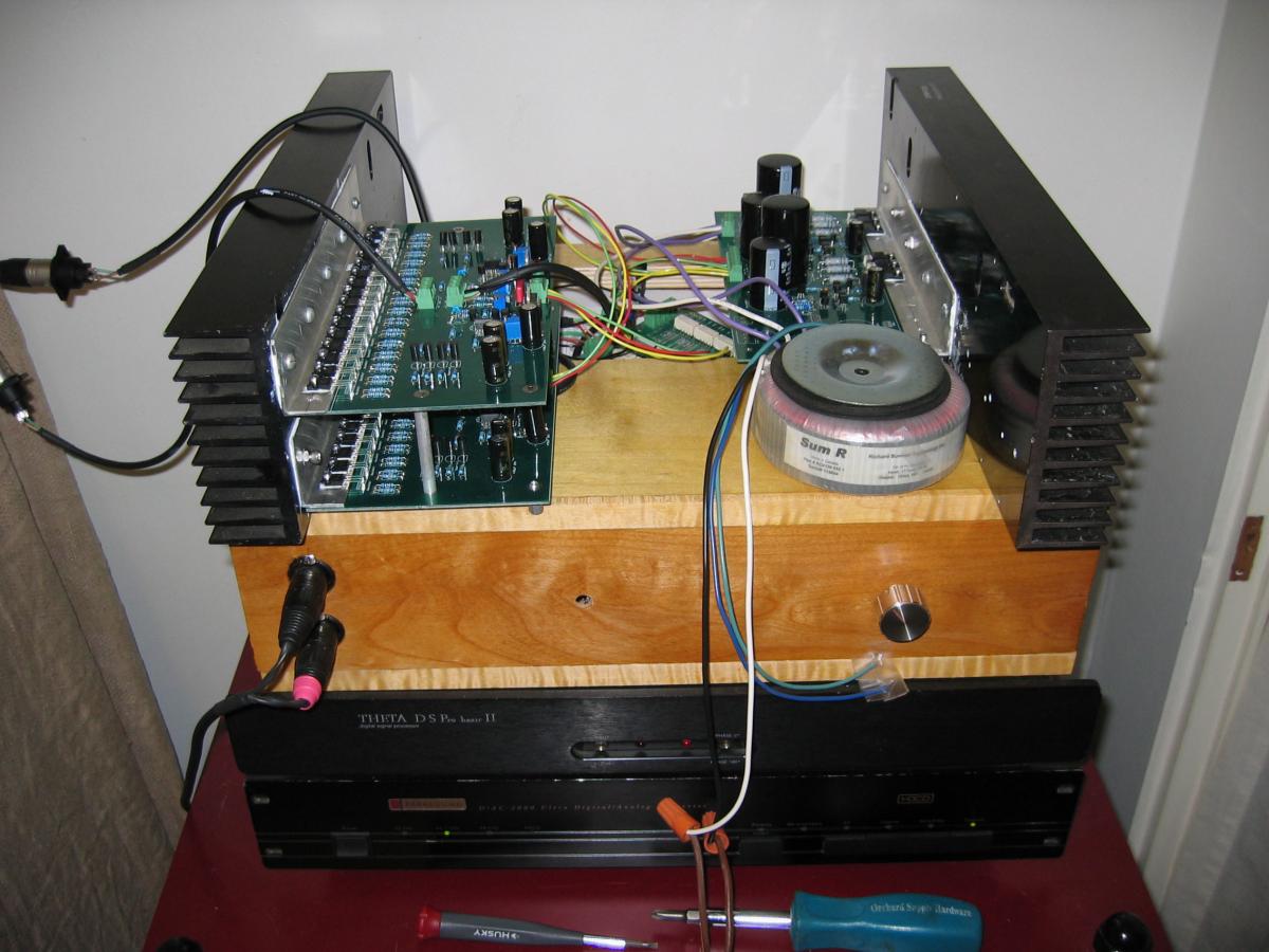
After some trial and error, we got the Dynahi to make music. And it sounds fantastic – prefer it to my balanced Dynalo with my grados (although it was built for Andy’s LCD-2). The following is what I learned in the process. There are a few discrepancies in the PS silkscreen as compared to the schematic: -R9 and R20 are 5K in the schematic and 10K in the silkscreen. -R15 is 10K in the schematic and 20K in the silkscreen. In both cases I followed the silkscreen. When powering up the amp boards the PS was blowing transistors. So I removed Q24, Q9, Q10, Q15, Q14, and Q26 (as per Dr. Gilmore’s suggestion), and populated 10KLO (left 40KDT unpopulated). With this configuration I was able to power up both amp boards. Initially I had a little trouble biasing and removing the offset in the amps. After some experimentation I got the offset down to 0. There was about 470 ohms across R1/R4 resulting in about 80 mv across the 20 ohm resistors. It ran really hot (about 60C on the heatsinks after about 15 minutes). To try to lower the heat I replaced R1 and R4 with a 680 ohm resistor and preset RV1 and RV2 to give 500 ohms across R1 and R4. This gave about 75 mv across the 20 ohm resistors. Still ran really hot. The problem is that my heatsinks have horizontal fins (as you can see from the photos). They don’t dissipate enough heat. Until these are replaced I’ll need to use a fan. Now to start building a case! Many thanks to all involved with this project - looking forward to listening with Andy’s LCD-2s!
-
Here is working code for volume plus balance: #include <Wire.h> int sensorPinVol = A0; // select the input pin for the volume potentiometer int sensorPinBal = A1; // select the input pin for the balance potentiometer const byte attSetAddr0 = 0x38; const byte attSetAddr1 = 0x39; const byte attResetAddr0 = 0x3E; const byte attResetAddr1 = 0x3F; const int numReadings = 12; // max readings for averaging const int relayLatchTime = 3; // time in milliseconds const int maxPotVariation = 4; // max allowed variation in pot voltage without changing volume int currVol = 0; int currBal = 0; int volReadings[numReadings]; // array to hold volumes (for averaging) int balReadings[numReadings]; // array to hold balances (for averaging) int volReadIdx = 0; // readings array index for volume int balReadIdx = 0; // readings array index for balance void setup() { for (int i = 0; i < numReadings; ++i) { volReadings = GetVolumeSetting(); balReadings = GetBalanceSetting(); } currVol = GetVolumeSetting(); currBal = GetBalanceSetting(); delay(1000); } void SetVolume(int newVol) { boolean balChanged = SetCurrBalance(GetBalanceSetting()); // put avg volume into newVol volReadings[volReadIdx] = newVol; volReadIdx += 1; if (volReadIdx == numReadings) volReadIdx = 0; int total = 0; for (int i = 0; i < numReadings; ++i) total += volReadings; newVol = total/numReadings; // include only if relay chatter because of pot voltage variations if (abs(newVol-currVol) < maxPotVariation) { if (balChanged) newVol = currVol; else return; } else currVol = newVol; int leftVol; int rightVol; if (currBal < 125) { leftVol = newVol; rightVol = newVol*127/currBal; if (rightVol > 255) rightVol = 255; } else if (currBal > 130) { leftVol = newVol*127/(255-currBal); rightVol = newVol; if (leftVol > 255) leftVol = 255; } else { leftVol = newVol; rightVol = newVol; } // now set int sendLeftVal = (byte)leftVol; int sendRightVal = (byte)rightVol; WireTrans(true, attSetAddr0, sendLeftVal); WireTrans(true, attSetAddr0, 0); WireTrans(true, attSetAddr1, sendRightVal); WireTrans(true, attSetAddr1, 0); // now reset sendLeftVal = 0xFF ^ (byte)leftVol; sendRightVal = 0xFF ^ (byte)rightVol; WireTrans(false, attResetAddr0, sendLeftVal); WireTrans(false, attResetAddr0, 0); WireTrans(false, attResetAddr1, sendRightVal); WireTrans(false, attResetAddr1, 0); } boolean SetCurrBalance(int newBal) { // put avg balance into newBal balReadings[balReadIdx] = newBal; balReadIdx += 1; if (balReadIdx == numReadings) balReadIdx = 0; int total = 0; for (int i = 0; i < numReadings; ++i) total += balReadings; newBal = total/numReadings; // include only if relay chatter because of pot voltage variations if (abs(newBal-currBal) < maxPotVariation) return false; // currBal remains the same currBal = newBal; return true; } void WireTrans(boolean begin, byte addr, int range) { if (begin) Wire.begin(); Wire.beginTransmission(addr); Wire.send(0); Wire.send(range); Wire.endTransmission(); delay(relayLatchTime); } int GetVolumeSetting() { // pot reading int sensorValue = analogRead(sensorPinVol); // convert to new range sensorValue = map(sensorValue, 0, 1023, 0, 255); return sensorValue; } int GetBalanceSetting() { // pot reading int sensorValue = analogRead(sensorPinBal); // convert to new range sensorValue = map(sensorValue, 0, 1023, 255, 0); return sensorValue; } void loop() { SetVolume(GetVolumeSetting()); delay(75); } BTW, these attenuators sound fantastic. Many thanks to Dr. Gilmore and Kerry! Steve
-
Here is code to control two attenuators (i.e. balanced) with a potentiometer. Wire pot pins 1 and 3 to 5v and ground, and the wiper to A0 (analog input 0). Should work for a single board as well. For balanced configuration jumper id pins 1 and 2 of the second board (to change the address). Based on the code previously posted by Kerry. #include <Wire.h> int sensorPin = A0; // select the input pin for the potentiometer const byte attSetAddr0 = 0x38; const byte attSetAddr1 = 0x39; const byte attResetAddr0 = 0x3E; const byte attResetAddr1 = 0x3F; const int numReadings = 12; // max readings for averaging const int relayLatchTime = 3; // time in milliseconds const int maxVolVariation = 3; // max allowed variation in pot voltage without changing volume int oldVol = 0; int readings[numReadings]; // array to hold volumes (for averaging) int readIdx = 0; // readings array index void setup() { for (int i = 0; i < numReadings; ++i) readings = GetVolumeSetting(); oldVol = GetVolumeSetting(); delay(1000); } void WireTrans(boolean begin, byte addr, int range) { if (begin) Wire.begin(); Wire.beginTransmission(addr); Wire.send(0); Wire.send(range); Wire.endTransmission(); delay(relayLatchTime); } void SetVolume(int newVol) { // comment out if volume control works in reverse //newVol = 255 - newVol; // put avg volume into newVol readings[readIdx] = newVol; readIdx += 1; if (readIdx == numReadings) readIdx = 0; int total = 0; for (int i = 0; i < numReadings; ++i) total += readings; newVol = total/numReadings; // include only if relay chatter because of pot voltage variations if (abs(newVol-oldVol) < maxVolVariation) return; oldVol = newVol; // now set int sendVal = (byte)newVol; WireTrans(true, attSetAddr0, sendVal); WireTrans(true, attSetAddr0, 0); WireTrans(true, attSetAddr1, sendVal); WireTrans(true, attSetAddr1, 0); // now reset sendVal = 0xFF ^ (byte)newVol; WireTrans(false, attResetAddr0, sendVal); WireTrans(false, attResetAddr0, 0); WireTrans(false, attResetAddr1, sendVal); WireTrans(false, attResetAddr1, 0); } int GetVolumeSetting() { // pot reading int sensorValue = analogRead(sensorPin); // convert to new range sensorValue = map(sensorValue, 0, 1023, 0, 255); return sensorValue; } void loop() { SetVolume(GetVolumeSetting()); delay(50); } Hope this helps, Steve