Everything posted by kevin gilmore
-
-
-
the ultimate in insanity is a pair of krell master reference monoblocks driving stax headphones. or he6's, your choice.
-
-
-
-
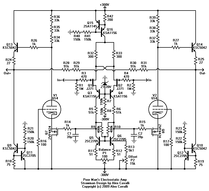
also notice that the whole case is aluminum extrusions. So new chassis again. at least the tube is much better and lower distortion and wider frequency response than the mosfet as the voltage gain stage. Now the output stage that sucks all the power is completely useless. only one transformer now so there had better be a delay circuit for the high voltage otherwise the tubes are not going to last very long.
-
definitely moar better.
-
I can post pics of the original. And the burned circuit boards that resulted from no heatsinks because the bias was 4 diodes and all over the map. This really is the original design. With a real bias generator and a dc servo because you can't get those output caps anymore, and why would you want them anyway.
-
yes 10ma in the output stage. That's 80% of the tube rating. you can use the other parts, but they are not as temperature stable.
-
-
That is right depending on the second stage zeners. If unreg voltage is at least 35 you will be fine
-
-
yep, the input fet has been fixed. also, next version of the kgsshvk board has it fixed too. (at least I think its fixed, please check) hv transformer is going to be lower voltages. best idea to have a separate filament transformer and time delay. current power supply board works fine with the resistors adjusted for 400v which means the unregulated voltages should be about 465v. will post newest picture, same name in a few minutes
-
-
-
as far as I know the portable is not an electrostatic amp. I have a great design for a portable electrostatic amp. Every time I try to get someone to build me the switching power supply transformer, they either cannot deliver, or what they deliver is so low in efficiency that it would eat batteries way to fast. What I really want is stacked printed coils on kapton. anyway, the stax mafia does not let grass grow under their feet. http://gilmore.chem.northwestern.edu/kgst.jpg solid state/tube hybrid done right, and actually pretty cheap.
-
enough people have been asking for this, we finally decided to do it. It was easy from the current layout. Best to stick with +/-400v power supplies http://gilmore.chem.northwestern.edu/kgst.jpg
-
-
From what I've heard, the current sources for the tubes are the same cascode in the same exact physical place. Meaning the same screws you can't remove from the triple of small heatsinks. So all you have to do is dump the rest of the crap and drop in 4 tubes. Basically the same as the exstata tube version without the bipolar output stage. Very simple circuit. I could draw it up in a few minutes. The only issue is what the tubes are, and what the power supply voltages are. since evidently there are no other heatsinks on the board, likely its not grounded grid design. Probably a couple of hours of board layout max. I could turn something like that around in one day, and get pcbnet.com to deliver boards in 3 days. Its going to sound way better than the mosfet pile of crap. And be pretty much identical to tube based stax product of the middle 1970's. Still going to be built like shit.
-
-
with those size paws, looks like its going to be a fair bit bigger than that.
-
how big is puppy supposed to get?
-
-
that schematic is for one channel plus a little bit. so there should be 8 power output cathode resistors total.