kevin gilmore
-
Posts
7,204 -
Joined
-
Last visited
-
Days Won
21
Content Type
Profiles
Forums
Events
Everything posted by kevin gilmore
-
ttc004 might now be a better replacement, different package.
-
simmcon, first graph not shown. are you measuring balanced? and what additional attenuator are you using?
-

KG Balanced Dynahi build discussion thread
kevin gilmore replied to Vortex's topic in Do It Yourself
those resistors are output stage bias set. -
KG Balanced Dynahi build discussion thread
kevin gilmore replied to Vortex's topic in Do It Yourself
no idea, have to look where those resistors go. if those are the input resistors, anything over 50 ohms is fine. -
and now for something completely different part 3
kevin gilmore replied to kevin gilmore's topic in Do It Yourself
there are gerbers for the k489/j689 and the 2sc3381/2sa1349 pretty sure the 2sj109/2sk389 is compatable with the 2sc3381/2sa1349 board you are looking for that340.zip -
and now for something completely different part 3
kevin gilmore replied to kevin gilmore's topic in Do It Yourself
the inductance is going to be really low in any case. -
your first link definitely works. But i have an extremely old version of this Precise Universal Hand Tapper, Assures Straight Perpendicular Tapped Holes - 265-110 - Penn Tool Co., Inc and this is definitely works, hard to use in volume applications Precise Mini E-Z Hand Tapper, Assures Straight Perpendicular Tapped Holes - 390-252 - Penn Tool Co., Inc
-
thats a great way to break a tap and ruin the heatsink. get a tapping jig.
-
and now for something completely different part 3
kevin gilmore replied to kevin gilmore's topic in Do It Yourself
that is one of the ways of building it. -
if you can't copy it now...

-
well there are 2 ways to do this. instrumentation amp and inverting/non inverting. pick one, they are roughly equivalent.
-
Megatron Electrostatic Headphone Amplifier
kevin gilmore replied to kevin gilmore's topic in Do It Yourself
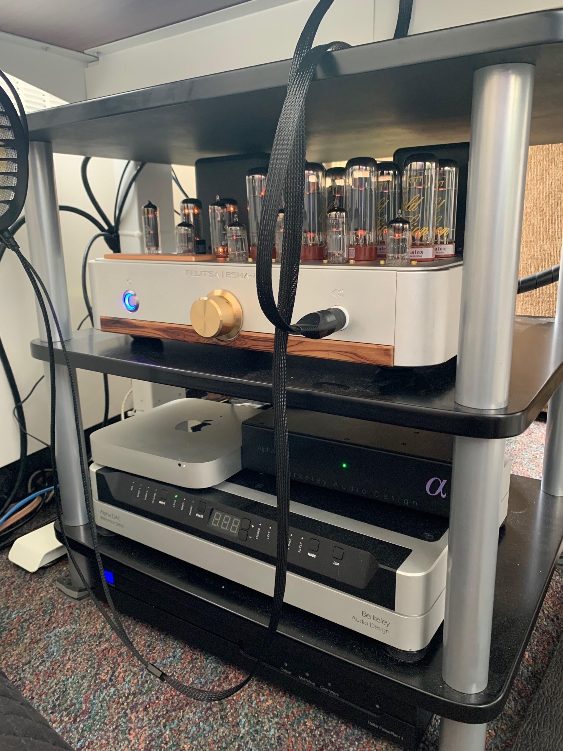
posted for the owner who will comment much further. (for some reason he cannot publish high res pictures)
-
there is no way this is going to be a diy product.
-
and now for something completely different part 3
kevin gilmore replied to kevin gilmore's topic in Do It Yourself
lazy huh? ubaltobaltubeschem2 - cadcam.zip ubaltobaltubeschem2flip - cadcam.zip -
and now for something completely different part 3
kevin gilmore replied to kevin gilmore's topic in Do It Yourself
there are already tube input versions. but this version does not have a servo on the output board, so it would need that. there is a version of that too, outputbuf2020 and outputbuf2020m -
i found the synthesis file it is now posted in the documents directory cfaelectrostaticschem.pdf in the boards share there is cfaelectrostat.zip and electrostat2.zip there are other surface mount versions that have not been posted next time don't post twice, and you can always ask me
-
stax mafia circuit boards see updated links on page 5
kevin gilmore replied to kevin gilmore's topic in Do It Yourself
i found the synthesis file it is now posted in the documents directory cfaelectrostaticschem.pdf in the boards share there is cfaelectrostat.zip and electrostat2.zip there are other surface mount versions that have not been posted -
and now for something completely different part 3
kevin gilmore replied to kevin gilmore's topic in Do It Yourself
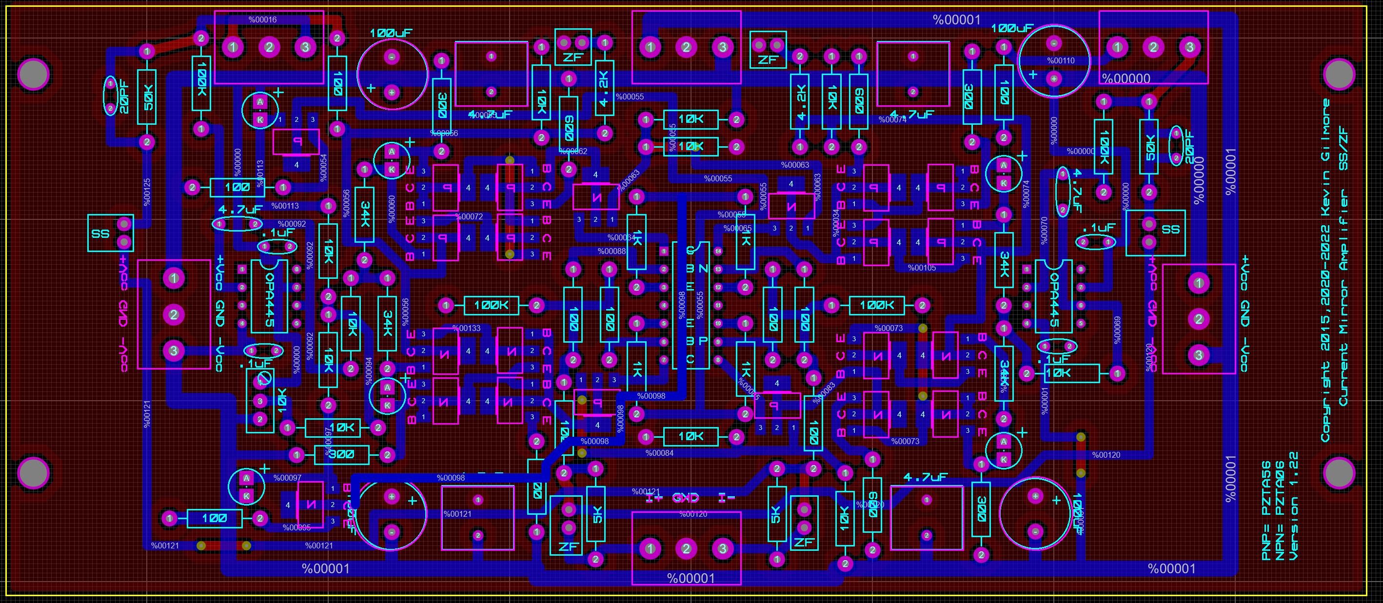
so split versions of the cfa3 board. stack the boards together and put on the heatsink (minimum heatsink vertical dimension 83mm) stack the boards together, use angle bracket mount horizontally for low profile chassis etc cfp3smt2splitamp - CADCAM.ZIP cfp3smt2splitpre - CADCAM.ZIP
-
and now for something completely different part 3
kevin gilmore replied to kevin gilmore's topic in Do It Yourself
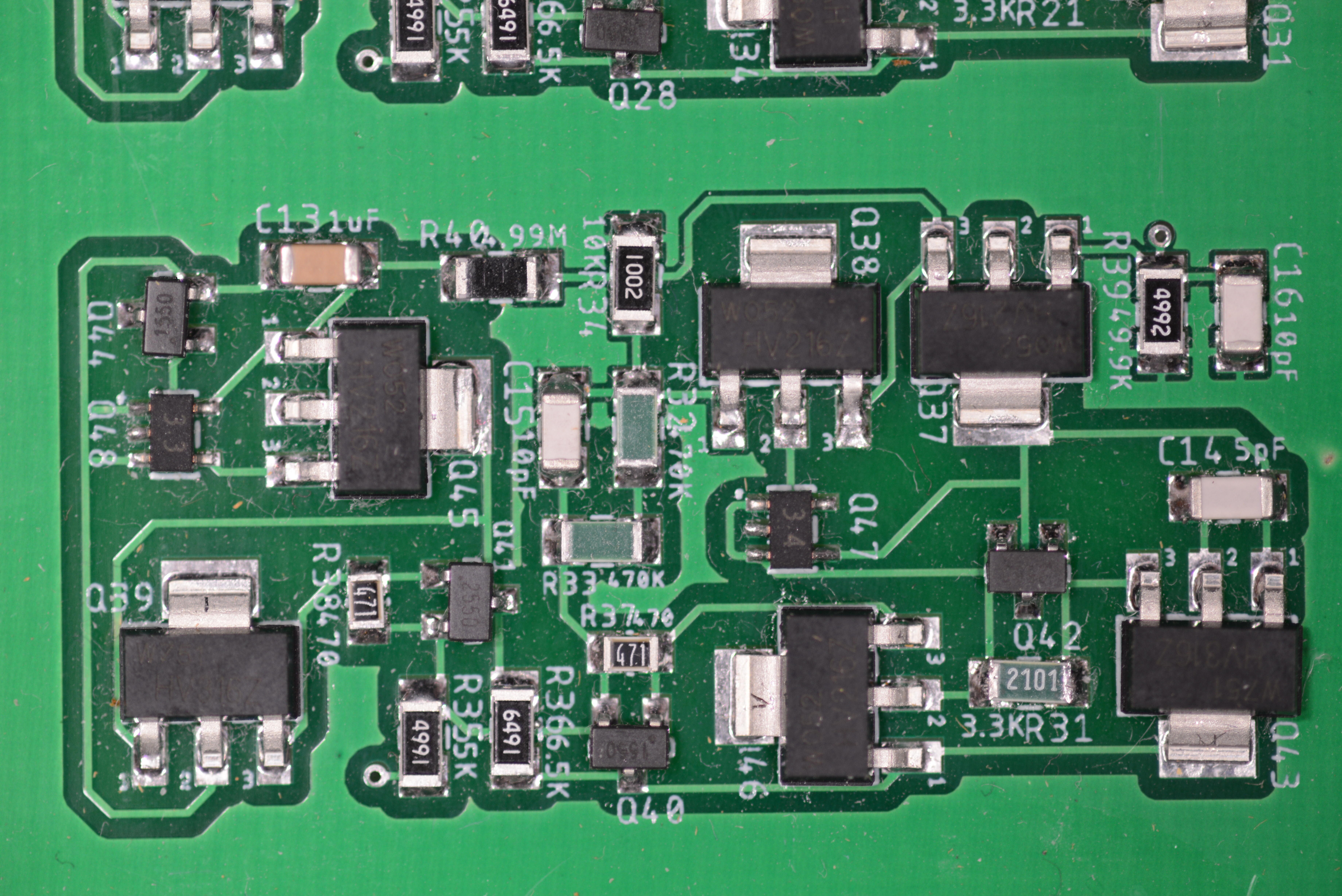
so i have got a number of contacts, most with felista built amps, definitely with fake toshiba transistors that blow up. Now another person with toshiba parts with the amp oscillating. Other changes were made, so who knows, and no idea if the transistors are real or fakes. being discontinued more than 10 years ago, everything on ebay has to be fake. so word of warning to people building them and trying to use toshiba (fake) parts. no way to know if they are fake unless you use a transistor tester. biggest tell is that they test barely at 25-30 volts instead of 120 -
Megatron Electrostatic Headphone Amplifier
kevin gilmore replied to kevin gilmore's topic in Do It Yourself
A tube diode CRC power supply driving GRHV would have slightly lower noise. -
Megatron Electrostatic Headphone Amplifier
kevin gilmore replied to kevin gilmore's topic in Do It Yourself
you are going to need a pile of floating filament transformers. although now that SumR has finally produced transformers that are the right voltage and run cool this is easy. this one has regulated 300v and RCLCC high voltage supplies each with tube diodes. that is 2 more transformers. This one is 211 watts. A standard T2 is about 250 watts. replacing the current sources with tubes will add another 80 watts. and lots more physical space. and more filament transformers This modified to fit amplifier board will not be published and would be useless to everyone. The standard amp board should be used. The 300v regulated tube board with the tube hv diodes would be publishable once i put all the tube sockets back on standard distances. The hv power supply board would be publishable if people are interested. both of these would only be released to people who promise not to let them fall into the hands of FUCKING INCOMPETENT MORONS. -
and now for something completely different part 3
kevin gilmore replied to kevin gilmore's topic in Do It Yourself
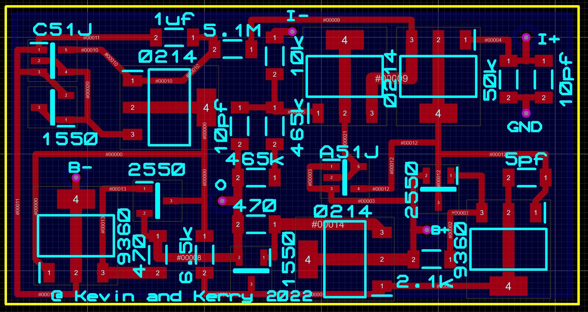
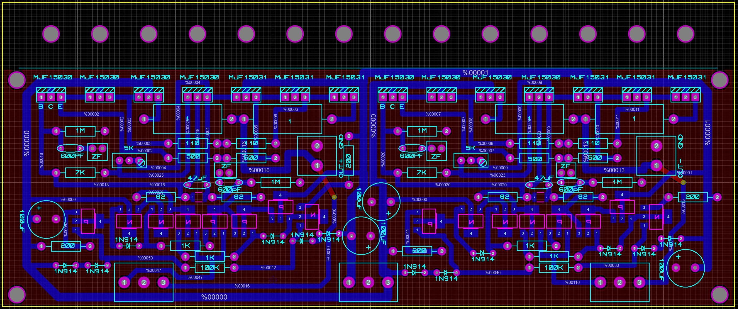
its zero feedback or super symmetry. can't be both. a couple of people have made relay switches that switch from one to the other. all SS jumpered for SS all zf for zf mode. -
Megatron Electrostatic Headphone Amplifier
kevin gilmore replied to kevin gilmore's topic in Do It Yourself
by matching the tubes. its +/-5 volts typically. -
Megatron Electrostatic Headphone Amplifier
kevin gilmore replied to kevin gilmore's topic in Do It Yourself
you can expand the picture and read it NOT Felista Audio OTL Push-Pull Electronic Headphone Amplier For the record this is not a push pull amplifier. -
and now for something completely different part 3
kevin gilmore replied to kevin gilmore's topic in Do It Yourself
i would check this real hard to make sure i did not introduce any errors. cfp3smt2 - CADCAM.ZIP