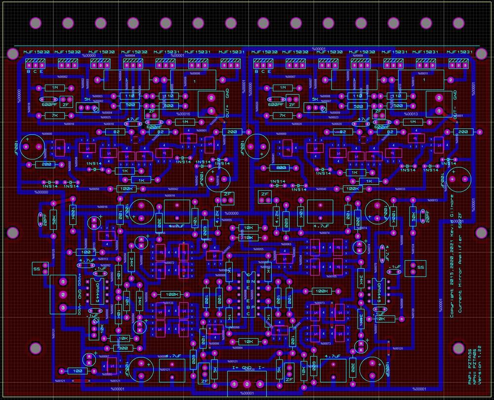
kevin gilmore
High Rollers
-
Joined
-
Last visited
Everything posted by kevin gilmore
-
i'm assuming that all the meter numbers don't change when the channel cuts out? which kind of eliminates the front end tubes and circuitry?
-
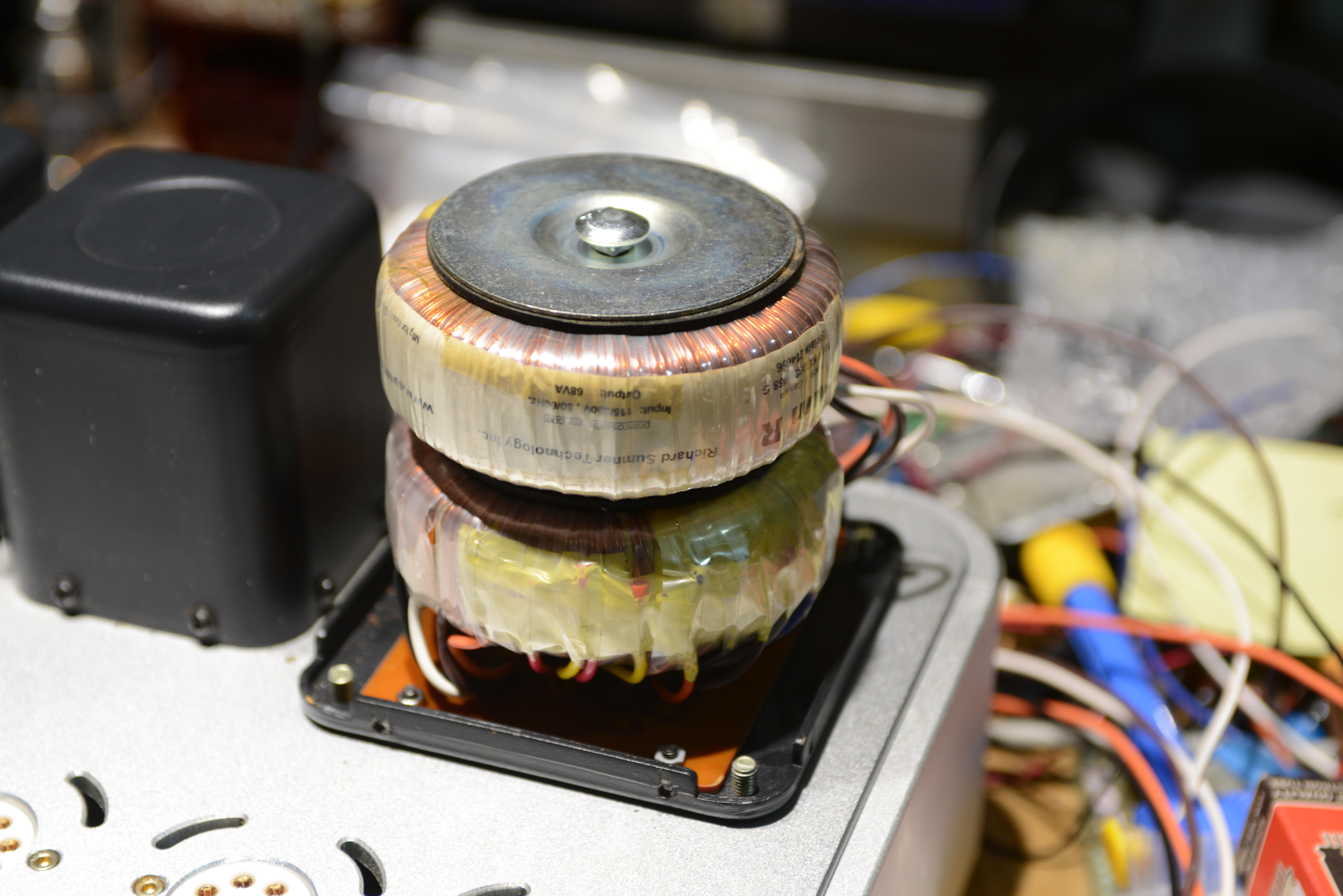
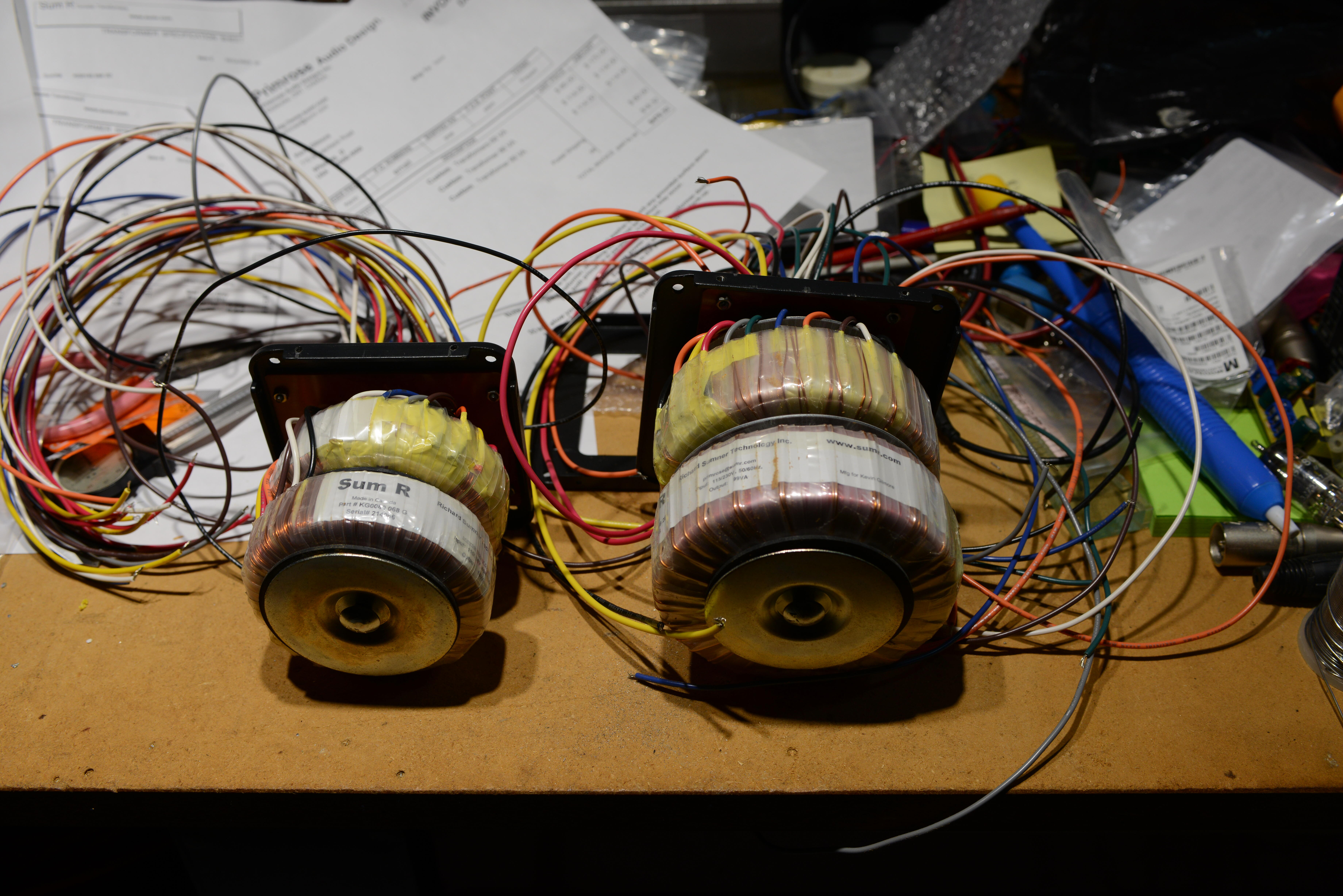
both transformers now have shorted primaries. And the smell of burned toast. This is just driving the filaments and every output tube was getting about 6.2 volts. (and input tubes were getting 12.5 volts) transformers are 68va and say so. each drives 4 x 6ca7/el34 plus a 12au7 and 12ax7 4 x 6.3 x 1.5 = 37.8 watts 2 x 12.6 *..15 = 3.78 watts so a total of 40 watts should have worked.

-
good news, BAD news as far as i know, this is not safe.


-
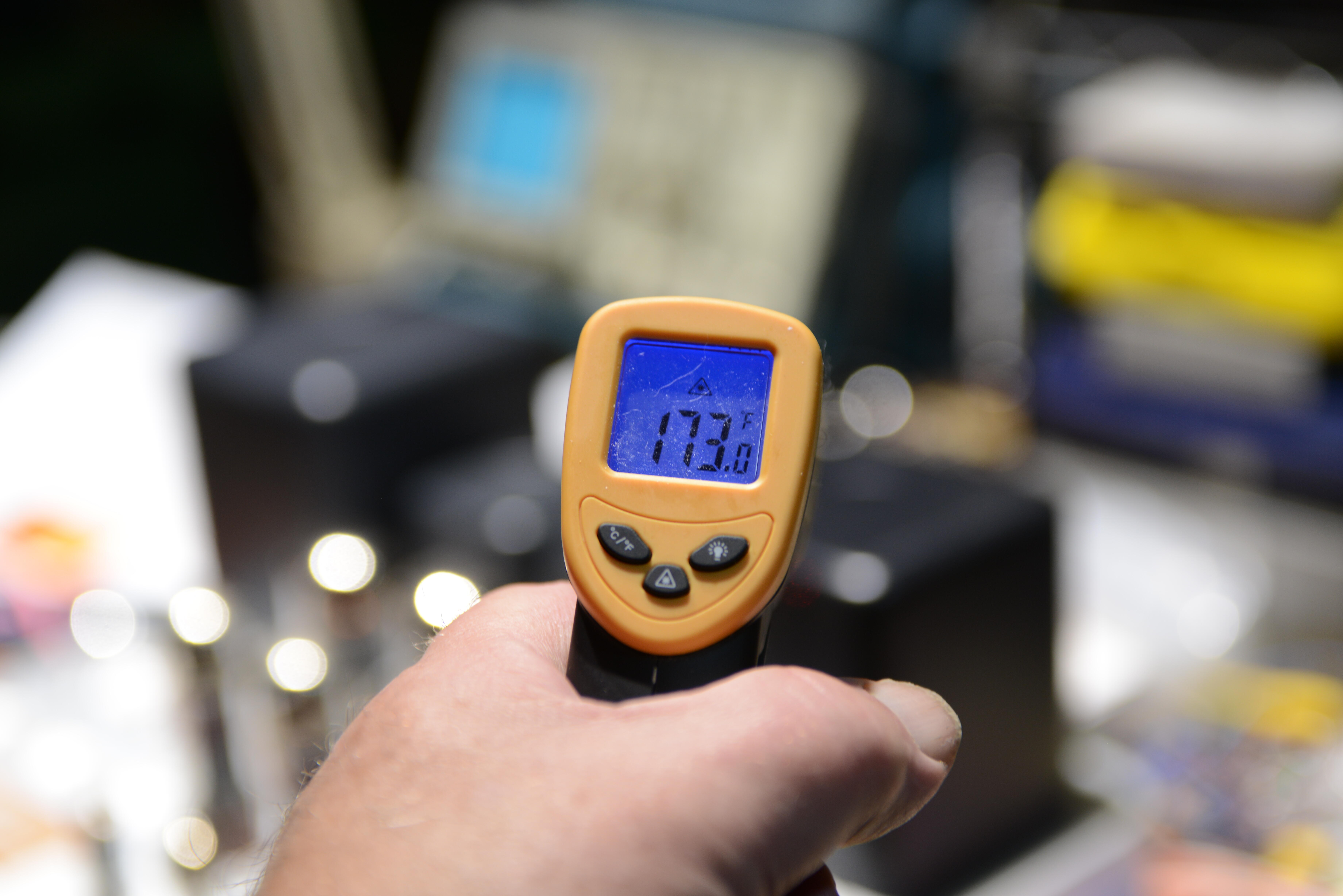
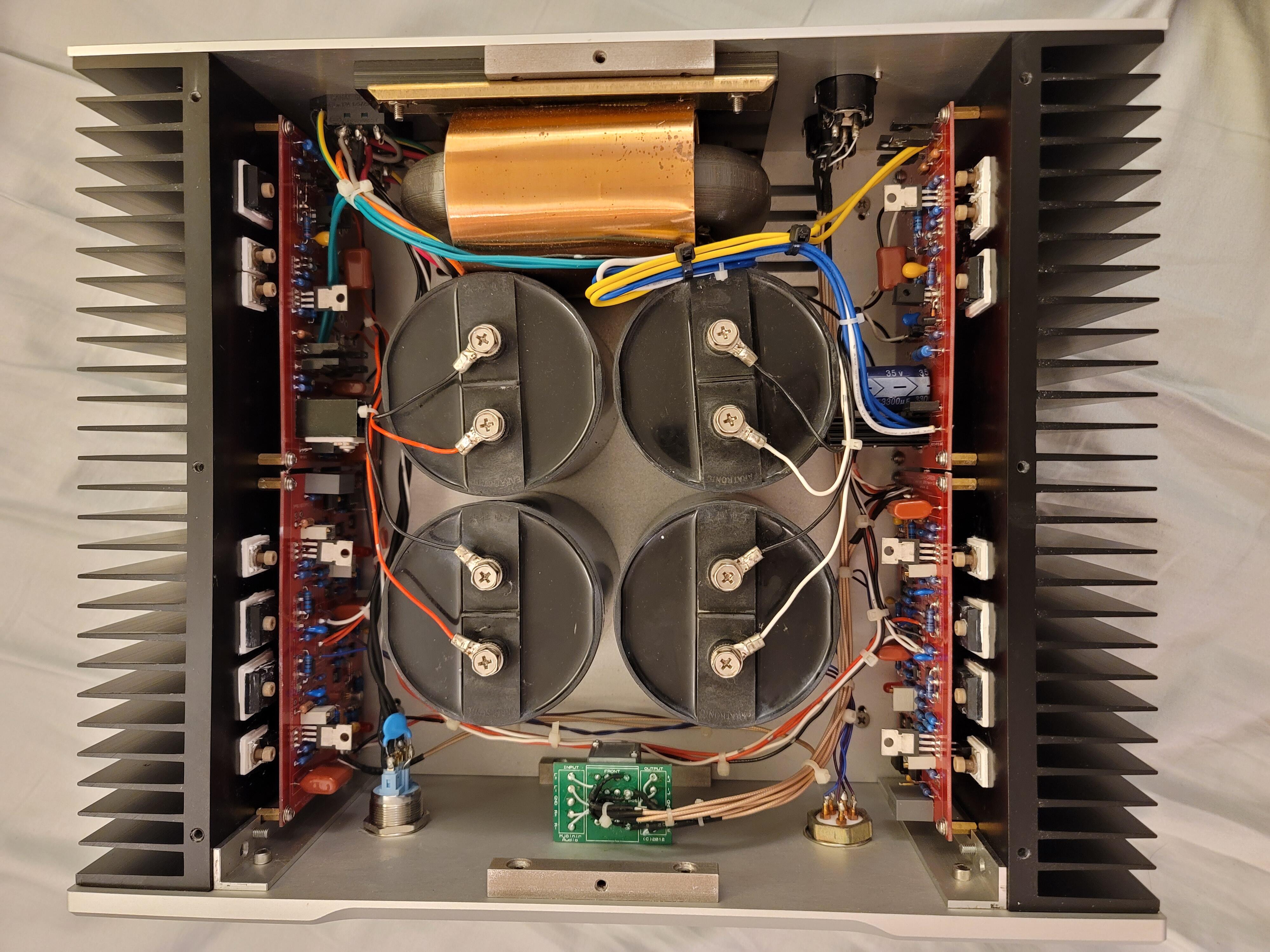
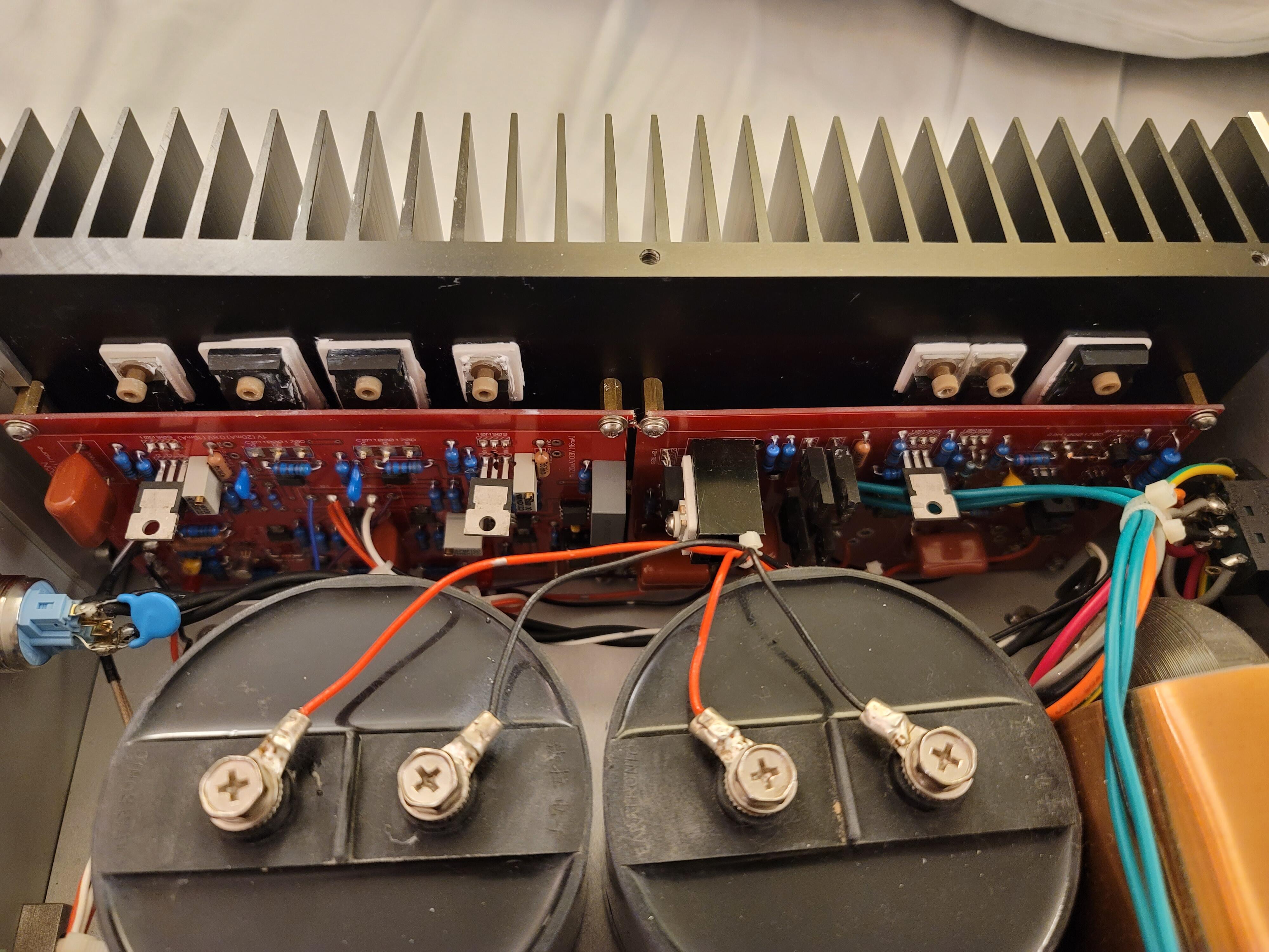
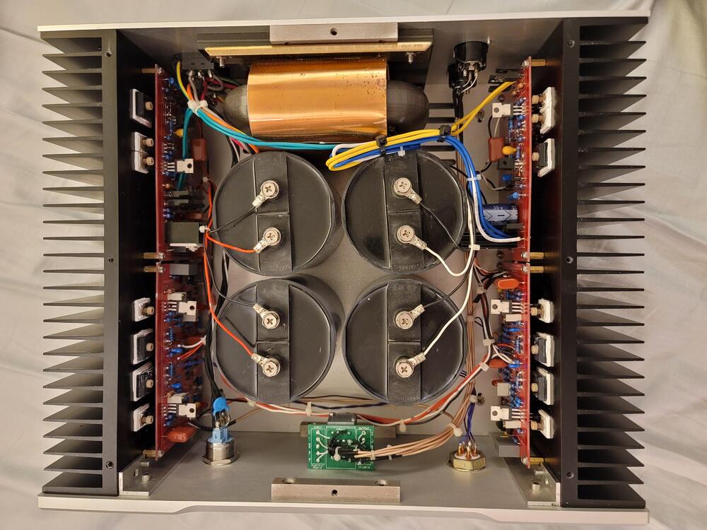
it is possible that parts of the power supply are dual mono and one side is getting too hot for some reason, or one of the electrolytics is causing trouble. Get an infrared thermometer and see if anything is getting hot.
-
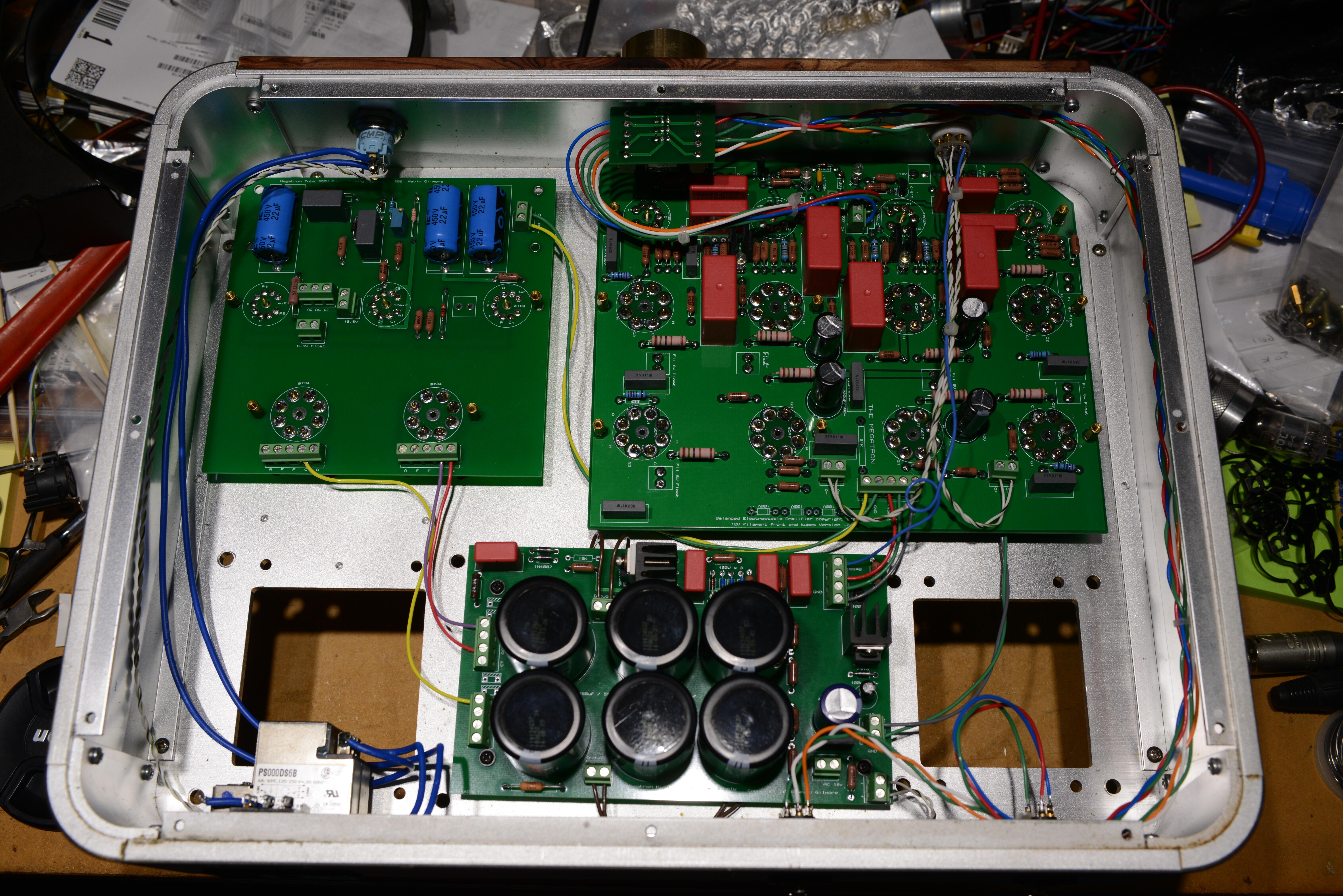
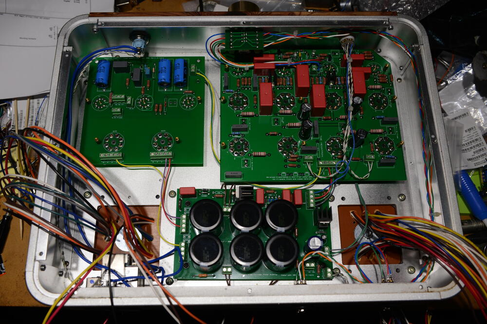
in the past, craig had trouble with all those white plastic connectors with poor crimp on the pins. look carefully for browning or burning on these connectors, removing them one at a time and reseating them.
-
so many wires

-
bc546/bc556 starting to get very hard to get even though onsemi says they are going to make more, so this which needs massive amounts of checking.
-
new document link https://drive.google.com/drive/folders/152thxfZafBmisG0CKCv6X82V-Ch9TjMH?usp=sharing
-
will try and fix later.
-
here are the current google share links https://drive.google.com/drive/folders/1r3g2TAtBUaBdiMorTWX7yYgeJ7maQbYW?usp=sharing https://drive.google.com/drive/folders/152thxfZafBmisG0CKCv6X82V-Ch9TjMH?usp=sharing someone please verify that both links are viewable.
-
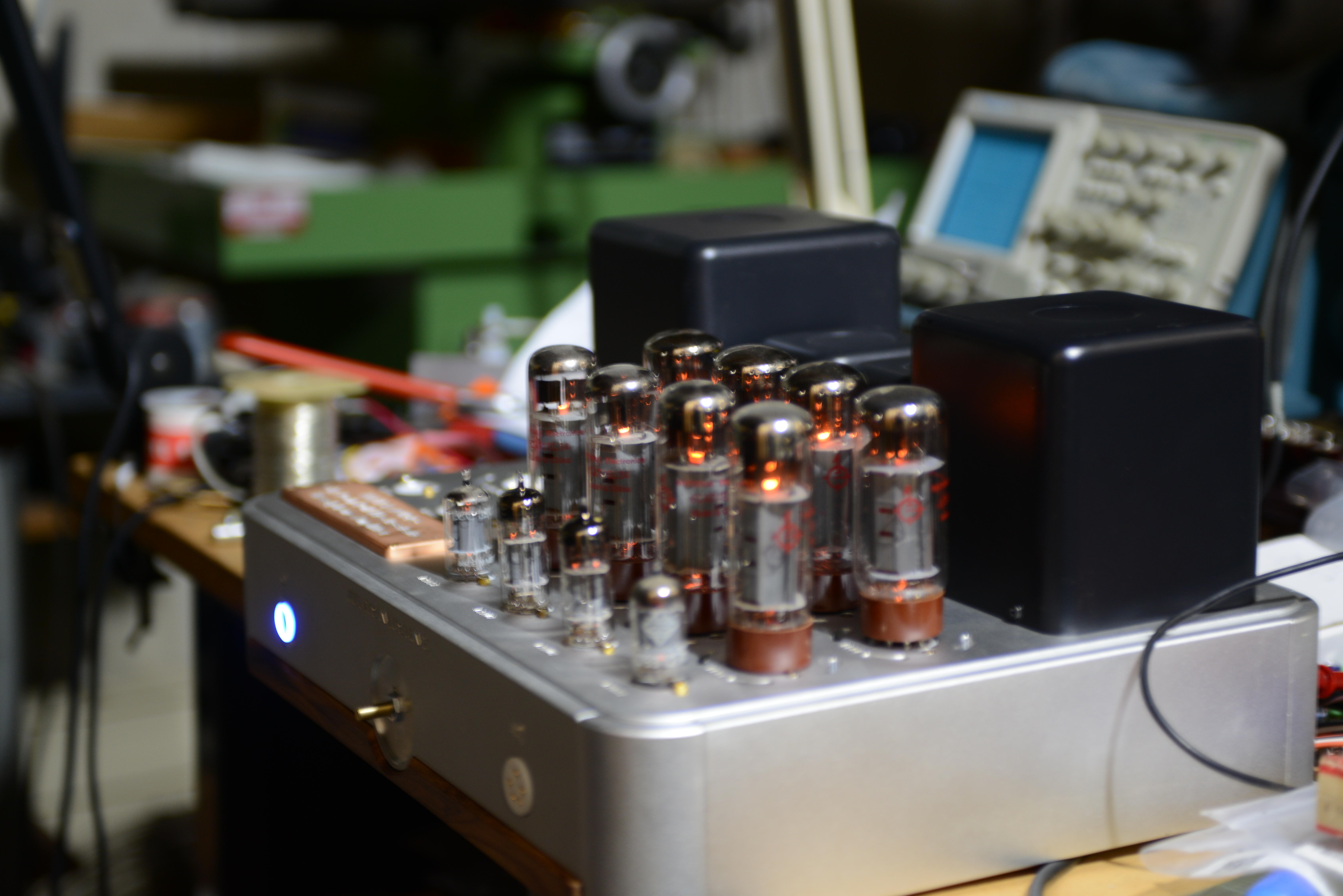
and some correspondence that is truely amazing in so many ways (cut and paste from corrupted adobe file) seriously people, read all of this! I am thinking of having my reference Stax amp find a new good home and fund for another projects. This is something you rarely see for sale. The design is based on the Megatron by Kevin Gilmore but is heavily revised to be a truly tube amp, straight from the power supply to the amp section. 2 separate power transformers, one for high voltage, one for filaments. Another 2 chokes to filter for the power supply. All of these are hand-winded in house, using the Kawasaki 0.23mm core. Tube config for the amp section is 2x 12AU7, 2x 12AX7, 8x EL34. Power supply is something unique you rarely see elsewhere, 2x GZ34 as rectifiers for the EL34s, EZ81 + EL84 + 12AX7 makes a rectifier and voltage regulator config for the input stage. No solid state devices are used here, just pure tube sound. Everything inside is point-to-point wiring, utilizing custom made base boards for tidiness. TKD potentiometer. Single-ended input only. Let me know if you really need balanced input. The chassis is extremely well-built and heavy, full of machined aluminum. There is also a decorative copper plate on top. My own custom teflon Stax jack (wrong direction in the photos but I already switch it ). I specially made a trim of rosewood to make it classier, who doesn’t love tubes and wood? Custom gold screws on the the top plate do improve the look a lot. The amp could run on either 115v or 230v, just flip a switch in the rear panel. This is just a piece of art you could proudly show off. It’s quite sight to see it run at night. Of course, the sound is marvelous. You have all the fun to try out new tubes, new coupling caps. I could do all kind of upgrades if you are interested and don’t want to mess with high voltage stuff. Pls keep in mind the amp is HEAVY and shipping will be quite a bit. Asking price is $5,500 plus PP fee and shipping. Quite a steal for an amp at this class. It’s a level above the BHSE in terms of musical and powerful sound. The hybrid design takes away the pure tube sound that Stax loves. The Carbon is a beef up KGSSHV. It sounds really like the BHSE. The T2 is the only amp that could sound better than my Megatron, but that would cost you twice the price. There’s no one would build one and ask less than $10K Ha, you found me there! That amp is a custom unit that I built for someone really loved the big 845 tubes. I no longer had it when I finished the Megatron, the customer couldn’t just wait anymore to bring it home. No chance to really compare side by side. As far as I remember, they are kind of 2 different monsters. The Megatron has the traditional Kevin Gilmore’s sound, very balanced with superb low end, truly tube sound, without add the harshness of solid-state. The 845 is much more difficult to build, the sound depends heavily on the output transformers. My customer spent heavily on the custom transformers to have the very best one. It has spacious, lush, sweet sound, but not as detailed and bassy as the Megatron. One problem is the cost, it’s actually as much as the T2 due to the exotic transformers, taking many hours to painstakingly wind. Too much time consuming, I must say. If I had to build a tube amp again, I’d build the Megatron which has more stable sound, not having to depend on expensive parts, you build it right, you get the exact sound. If I ever got an unlimited budget, the #3 baby will be bornt with all kind of wildest and craziest idea for a headphone amp. It’s the cost and time that keep me away from it. Good thing though. The power tubes EL34 are indirectly heated. The ones like the 300B, 2A3 or 845 are directly heated, they are much harder to work with because of the noise. The ESHA-1 is single-ended, not push-pull. It’s also output transformer coupled. Only the power 845 tubes are directly heated, the input tubes are indirectly heayed. As I said they are two totally different beast, each has its own sound signature, even though they may sound really close in some genres. The ESHA-3, if ever built, would be like a double of the ESHA-1. It would be a monster, way way overkill, even for speakers. ESHA-1 is: “Direct Heated Triode Direct Coupled Single Ended Output Transformer-Coupled†ESHA-2 is: “All Indirect Heated Triode Direct Coupled Push-Pull Output Transformer-less†Seriously only the EL34 tubes in the ESHA-2 could do the job fine. Other ones like the 300B or the 845 in the ESHA-1 are either low powered or very hard to make them dead quiet, especially with the very sensitive 007/009. Yes, it was initially running at 1050V but later on I kept it at 650v. The headphones don’t need that much power to run at such high voltage, that’s the range of very low senstive speakers. The ESHA-2 runs on +-500V (limit of the EL34 tubes). BHSE +-400v. The ESHA-3? I’m not really sure, depending on who would own it. If that’s my customer, then it would run 700-750v for safety. If that’s my own, probably at least 1000v Yes, the 4x845 is exactly what the ESHA-3 would look like. Twice the ESHA-1 in both power supply and amplifier section. Lots of questions, I can tell you are very eager to learn more. This Megatron is actually my second build. The first one was built out of curiosity after I’ve all kind of solid state and hybrid designs by Kevin Gilmore. Each design has its great sound, KGSSHV - fantastic and most valuable ‘starter’ amp, for $2500 in these days market, it’s a steal! , Carbon - a more muscular KGSSHV with more expensive parts and work to do, Blue Hawaii - a ‘simplified’ T2, and lastly the grandfather of all electrostatic amps, the T2. Lots of history behind the T2, as you might know. Back in the past, Kevin Gilmore designed the Blue Hawaii when he was having a cocktail and thinking about the T2, designing the circuit basing on the descriptions he got, without having the real unit there. Later on to 2009, Birgir purchased a real T2 and sent it straight to Kevin to begin the process of reviving the legend. Months later, the first working T2 was alive and people began to build them. It’s a monster of headphone amp. So much attention and work must be paid in order to build. Most of the transistors to build it were totally no longer in production now, so you either overpay for them or buy them from various places, one from Germany, another one from an auction site in Japan, maybe some from ebay.... The cost of building it is one thing, the labor is another story. That’s the reason you rarely see a T2 on sale, people even reserve the amp! The sound is fantastic, transparent, lots of control. It’s a worthy amp to own due to its legendary status. All these work invested made me think, is there other ways to rival the T2? The tube world has so many options, I searched for months for ideas. One thing I bumped into was the amp Frank Cooter build for Jude. It’s a 3-stage DHT (directly heat triode) using the 845 tubes which are a very powerful, very high voltage, very spacious sounding. I really liked the idea of using big transmitting tube for headphones, not many people are able to build it due to the need for custom transformers and high voltage. I read some and got inspired by the Audio Note Ongaku, the considered best tube amp in the history. It utilizes the 211 which is another tube on the same level of the 845. It has only 2 stages, you would have a better taste of the power tubes. Also the power supply design using 4 rectifier tubes is also fascinating me. Manufacturers usually do cheap and use only 2 or even 1 rectifier tube and use the cheap solid state rectifiers too. So I merge all these ideas and the ESHA-1 was bornt on paper. I spents another month thinking about the design of the chassis, I want it something special and beautiful, something unique that nobody made before. It’s a combination of modern full aluminum and a touch of classics with gold volume knob and a trim of rosewood. The transformers, as I told, are the most important in single-ended amp. The circuit is simple, easy to make, but how good it sounds depending on the output transformers. Unfortunately there’s no such off-the-self one for Stax. My friend who have been making transformers for DIY-ers is a master of this. So I callled him, telling him about my idea, the specs of the 007/009... He said “okayy, this thing is stupid for headphones but who cares? Stop by my place and we will talk about it.†Days later I had a coffee at his shop, he dropped me his precious transformer cores from Japan and a bunch of papers on how to build it. I don’t remember how many times I called him for advice, but in the end, I’ve got something very special done. The customer was also very excited and kept pushing me. The first day I called him telling I got sound from the day, he was like “say no more, I will be at your house right now, just stay thereâ€. He heard the amp and said, “is this the best you can do?â€, I said “probaby yes, for now. I can tune the sound by upgrading some resistors and caps.†So after another round of investment for parts, he brought the ESHA-1 home with utmost happy. I suspect he would be the guy behind the ESHA-3 soon. After the success of the ESHA-1, the design I really wanted to come back and improve is the Megatron. My first build has really good sound but using simplistic chassis. Easy work here, I just redid it using the ESHA-1 core. One thing I would like to improve is the power supply section. The input stage normally just bases on solid state diodes and simple regulators, I decided to do it more by using all tubes. I don’t even think there is a commercial amp using this configuration, it’s just way overkill, more like a show-off! I also read Frank Cooter’s suggestions and tried them, not much difference though, so I sticked with the orginal design. The double chokes in the power supply help clear up the sound a lot. I want as much traditional tube sound as possible. Metal films resistors are used everywhere. Coupling caps are imported from the US. Volume potentiometer is TKD from Japan, one of my favorite! The amp also has a heavily filtered AC inlet. These tubes will last you way longer than you could expect. The stock tubes are already great, but you could try to roll the Gold Lions EL34, 12AX7, 12AU7 for the amp section. These are the best valuable in production tubes. They have controlled quality, unlike the random NOS ones. Power cable is not much an issue, but you could use medical grade one. I’m not sure about Canada’s socket type though. I built some for my customers and he was very satisfied with the result. I love talking about audio 🙂 Most of the fancy and interesting stuff about audio/headphones world are from the history. Having been at HF for almost 15 years, I’ve read lots of great stories. I won’t say the T2 parts is modest, honestly. The boards + transistors alone are $1,300. A pair of chassis is another $1,500 easily. Power transformers another $600. Caps + resistors + volume control $700-$1,500 depending on what you chose. Tubes are $200 for the cheapest. And builder will charge as much as the parts for labor, that’s the reason all of them are sold above $10k. Built properly, the T2 will survive 4-5 years before needing to maintenance. A risk is when something goes kaboom, you might be unable to obtain replacement parts 😕 It’s so easy to maintenance the ESHA series because all parts are always available. You have a peace in mind without worrying about failure. That’s great you have access to machines to work on the T2. Most of the time I just had local shops to do on single quantity, hence the high cost. I have plan to do one very last T2 with heatsinks machined from a solid block aluminum, something like Boulder or D’Agostino amps. Upgrades for the ESHA-2 mostly are tubes rolling, caps and resistors swapping. I have the Cornell-Dublier polypropylene caps in the amps. They are excellent caps for the cost, measured really well. A reasonable upgrade for these caps is the Mundorf or Mif-flex caps. Not as much difference as tube rolling though. Most of the parts I chose are industrial grade so they will work for years. The TKD pot is 2CP-601 which is an excellent pot. Its bigger brother, the 2511, was firstly used but somehow it had weird working way which affected the input impedance. I switched to the 601 and it worked perfectly. Yes, in this design, caps don’t really make much difference. You need two matched quads, that would be sufficient, not need for octet. It’s 1800v Vpp (+-450v supply), substracting a bit due to the tubes eating some power. Output current, I need to check again, so many variables during the tuning process so I can’t remember correctly. I just fool around with values that sound best to my ears but still within safe working points for the tubes. But it’s basically the same as original design, maybe a bit higher. There is really no need to try to stretch the tubes, not significant improvement in sound but will shorten the tubes life significantly. The GZ34 currently used are very great, there’s absolutely no need to replace them. Plus, honestly, those are rectifier tubes, there won’t be much difference swapping the same type. Don’t spend money on them. Nothing else worth worrying about, the amp doesn’t need any calibration when rolling tubes. I’ve been at HF for 15 years but as you see, I only have a couple hundreds posts, most of them were me clearing about stuffs. I just like reading and asking/discussing in private messages. I just looked at the papers again and the output current is approximately 10mA. Those numbers are actually just for references. The T2 clearly is a league above the BHSE but still it runs on lower current. Each core takes 2 days to wind, then another two days for vanishing and drying. My friend could do that in half the time it’s the material that matters. Exotic transformers makers from Japan even spend time making insulation papers from wood pulp. In the ESHA-3, I might switch to toroidal transformers to save height. My plan is two separate chassis and stackable. The tubes in the power supply will be mounted horizontally inside the chassis. The first one took me 8 hours to wind, the rest were faster. I don’t really remember how much time I invested in the amp, the fun of building is more than that. I had a request to build a Carbon in this same chassis style. Should be a fun project, even though I still haven’t taken the request. There are like 10 caps that I can upgrade. I will experiment with them to see which make the most improvement. The Japanese have some very nice, vintage paper-in-oil caps that they don’t export and only sell within Japan. Whenever my friend gets back here, he will deliver them for me. The amp’s operation depends on the mains voltage so when I switch to 115v, some need to be calibrated again. Those oil caps are quite rare, I also keep some for later use, in case I want to build the ESHA-2 again. The amp’s operation depends on the mains voltage so when I switch to 115v, some need to be calibrated again. Those oil caps are quite rare, I also keep some for later use, in case I want to build the ESHA-2 again. It’d need a long essay to talk about DAC because I’ve been spending as much time on DAC’s as on amps. 😊 It’s a trend now most manufacturers go back on R2R designs. HOLO is one of the top one doing R2R, I really like their build. From the internal photos I’ve seen, they do know how to design great DAC’s. I’ve heard many Schiit from meets but honestly I wasn’t much impressed, probably because of not having my familiar amp and ‘phones. The Soekris 1541 is also an interesting one, considering the designer was the one who began the R2R trend some years ago. It’s either the ES9038PRO, AKM4497 or discrete R2R now for top DAC’s. If I have to rank them, it’d be ES9038PRO (too dry, analytical) -> AKM4497 (warm, smooth) -> Discrete R2R (detailed, maybe a bit light in bass). My dream would be building a discrete R2R DAC with DHT tube (300B, 2A3, 45, 71A) output. That’d be an amazing one. Thomas Meyer (a German tube guru who owns ELROG) just introduced the 801A tube DAC at $18k 😃 I bet it’d sound marvelous. My last R2R NOS one was also quite fantastic but was limited due to budget and chassis size. I also built the PCM1704 DAC with discrete output stage, which was a crazy design with like a thousand of resistors. Calibrating it was a nightmare but totally worth it. Yes, my DAC has USB input. Actually it’s the USB that’s usually improved years by years, higher resolution, less jitter. Mac does work wonder with USB because they don’t require driver installed. It's a design by my friend, ultilizing the famous PCM1704U-K chip. It's $60/ea and the DAC requires 16pcs of them. So basically $1k just for chips 🙂 It's no longer in my possesion, really miss that monster! I don't have any DAC I could sell now, just having lots of ideas but haven't got time/budget to get it done. Soekris does offer DIY board that I really want to try some days, adding a nice output stage then I could be happy many years to come. Regarding the USB cable, honestly I don't think all these aftermarket cables out there are built with the right specs. Some conductors must be larger, some smaller to satisfy. All I can see is some fancy braiding work, just like analog cable. My advice is just buy a short one with gold-plated connectors, something from Belkin would do the job perfectly. Adding an USB isolator would be great too. The Thunderbolt cable seems to be hard to do, I suspect they have a tiny controller inside the connector. Hah, looks like he spent a lot of time trying tubes. The Gold Lions are indeed very special, great sound and new stock, which mean you could abuse them without worrying much. The NOS Siemens, Mullard or Telefunken are no doubt the very best but very hard to find 8 tubes that are tested and built the same. They are prone to fail anytime if you don’t take great care of them. ESHA-2 Tube Guide I’ve got the caps installed and the sound is a smoother a bit. There’s some more extension in the mid range too. My suggestion is you should upgrade the input tubes (12ax7 and 12au7) first. They have great importance to the sound. My friend stopped by today and he popped in his newly purchased Gold Lions tubes. I’m amazed at how clearer the sound is. The one 12ax7 in the power supply is quite important too since it decides how high to output voltage. I should be able to ship the amp in 2-3 days. Will need to find packing material. No I’ve calibrated all the stuffs to make sure it will work fine on either 115 or 220/230. The rectifiers are perfectly fine. There’s no need to think of any replacement. I popped in some expensive Mullard GZ34s which are easily $400 but haven’t noticed any difference. The EZ81 rectifier is also fine. The regulator 12ax7 and EL84 do affect on the sound though. As usual, I’d suggest the Genalex Gold Lions. They are newly made, well matched, long-lasting, simply the best among all these in production tubes. Power tubes, two matched quads. I’m using the new Electro-Harmonix. Great sounding tubes. If you could invest, either the Gold Lions or Shuguang 6CA7 is fantastic. EL34 and 6CA7 are same thing, but the 6CA7 has lower internal resistance, making the sound more transparent. My friends just tested with the input tubes. Input tubes, a pair of matched 12ax7 and a pair of matched 12au7. They should be the same brand, closely matched. These are the most important ones. I have a local vendor who carries all kind of new tubes and he agreed the Gold Lions are best seller. For tube amps, balanced connection really means nothing. The way they work just ask for single ended. Balanced is just for convenient. Great to hear the DAC is fine, I haven’t got chance to listen to it. I’ve got the caps installed and the sound is a smoother a bit. There’s some more extension in the mid range too. My suggestion is you should upgrade the input tubes (12ax7 and 12au7) first. They have great importance to the sound. My friend stopped by today and he popped in his newly purchased Gold Lions tubes. I’m amaze d at how clearer the sound is. The one 12ax7 in the power supply is quite important too since it decides how high to output voltage. Those are the 5u4g rectifiers. I switched to the gz34 later because of longer start-up time, which helps prolong the EL34s lifetime. The pure tube sound does have something special. It might not measure as well as solid state, but I prefer the Megatron to most of electrostatic amps I built and heard. RCA Cable: Likely Cap Issue: (Standby switch and warm-up time needed): https://el34world.com/Forum/index.php?topic=622.0 OTOH, most people around here will just say "stick anything in there, it works", which seems to be a general consensus when it comes to chokes as of late. People do say that regarding a cap-input supply, but only because a choke in those circuits only has to support the current of the preamp tubes and output tube screens. Also of note, there is an upper limit to the size of the choke you can use, as if you are not pulling enouhg continuous current, you can not create a big enough B field around the choke for it to do proper regulation, and it all goes to hell. That's a crucial point. Rule of thumb, the voltage at the first filter cap of a choke-input supply is 0.9 times the RMS voltage you're rectifying. For 500vac, you're talking about getting 450v. If you don't draw enough current, the action of the choke doesn't take place, and the voltage reverts to about 1.4 times the RMS voltage. That would put you at 700v. Not good.... Sounds like a standby to allow the heaters to warm up would be a very imprtant thing to have, not for the tubes (although they could be damaged) but for your filter caps. I'd still feel better about rating that first filter cap for the worst-case voltage. I went to a reliable source (Morgan Jone's book Valve Amplifiers) and looked up some choke-input supply info. He notes that in the "old days" the solution was to use a swinging choke. You have a very tough time finding those these days, so that's probably out of the question. He gives a detailed formula for the minimum current draw needed, but then goes on to note an approximation for 50/60Hz power supplies. It's Currentmin. (in milliamps) = VIn (RMS) / L (in henries). So for your 500vac transformer (which is RMS volts), you'd divide that 500v by the inductane rating of the choke you intend to use to see what the minimum current draw must be. As an example, for a 20H choke, 500v/20H = 25 milliamps of minimum current draw. The implication is you want a very high inductance rating for your choke. He also notes that it would seem the choke only needs to be rated for the maximum d.c. load current, but that the choke really needs to be rated in excess of this. Why? The choke generates a magnetic flux in the core proportionate to the size of the current passing through it, and if that flux is too great, it saturates the core and the inductance of the choke falls to zero. Bam! You're back at 700v. The current that the choke will support is the max d.c. load current and the instantaneous a.c. charging current (meaning the current used to charge the filter caps). So that's IDC + IAC = Itotal peak current. He derives a formula for the a.c. peak current. For a 60Hz wall outlet, it's IAC (positive peak) = VIn (RMS) / [1386 * L) Vin is the RMS transformer voltage again, and L is choke inductance in Henries. Here's an example he gave in the book, but with a slightly different formula for 50Hz operation: "A Class A power amplifier using a pair of push-pull 845 valves requires a raw HT of 1100v at 218mA, and a 10H 350mA choke is available, but is this adequate? The transformer supplying the choke has an output voltage of 1224VRMS, and using the equation for a 50Hz mains: IAC = VIn / 1155 * L = 1224 / (1155 * 10) = 106mA Itotal peak current = IDC + IAC = 218mA + 106mA = 324mA The total peak current is 324mA, so the 350mA is just barely sufficient ... " That shows that the choke needs to be rated in excess of the peak d.c. load current, which is the current the amp draws from the power supply at max power, not at idle. Once again, a choke with more inductance tends to ease your required ratings. But in all, you need to flesh out the design a bit more to properly rate the choke. Looking at this info, it's a very bad idea to just "slap something in" when you're thinking about a choke-input power supply. Jones also notes that regarding the power transformer, it simply needs to be rated for the d.c. load current. He gives an explanation for why, but it's enough to know that's the case. He does also note that the input choke creates voltage spikes seen by the power transformer. The solution is to have a snubber network, and he notes that the apparently best way of going about this is to fit 2 caps across the choke, with their "center-tap" connected to 0v. What this means is to use two 0.22uF 1kV caps connected in series, then take the outer leads and connect those to the choke to put this pair of caps in parallel to the choke, then connect the junction of the 2 caps to ground.
-
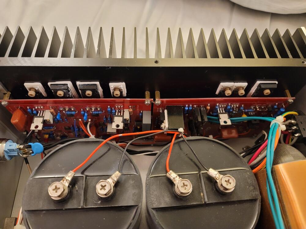
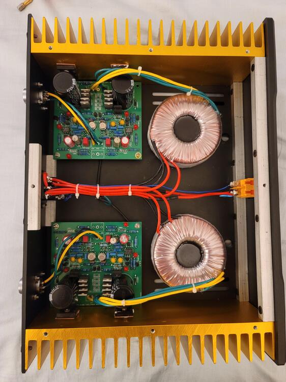
yep, i definitely do not see why this causes the lights to dim when you turn the power on. And a unique way of mounting the transistors to the heatsink
-
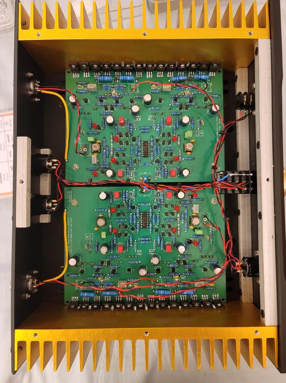
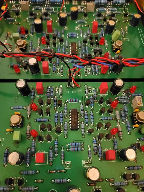
pics from rayofsi of tran's cfa3. slightly sloppy in places, but nowhere near the megatron fuck job. pics of carbon and ss dynahi coming later.
-
it was supposed to be the resistor or the current source. seems to work better with both. will know soon.
-
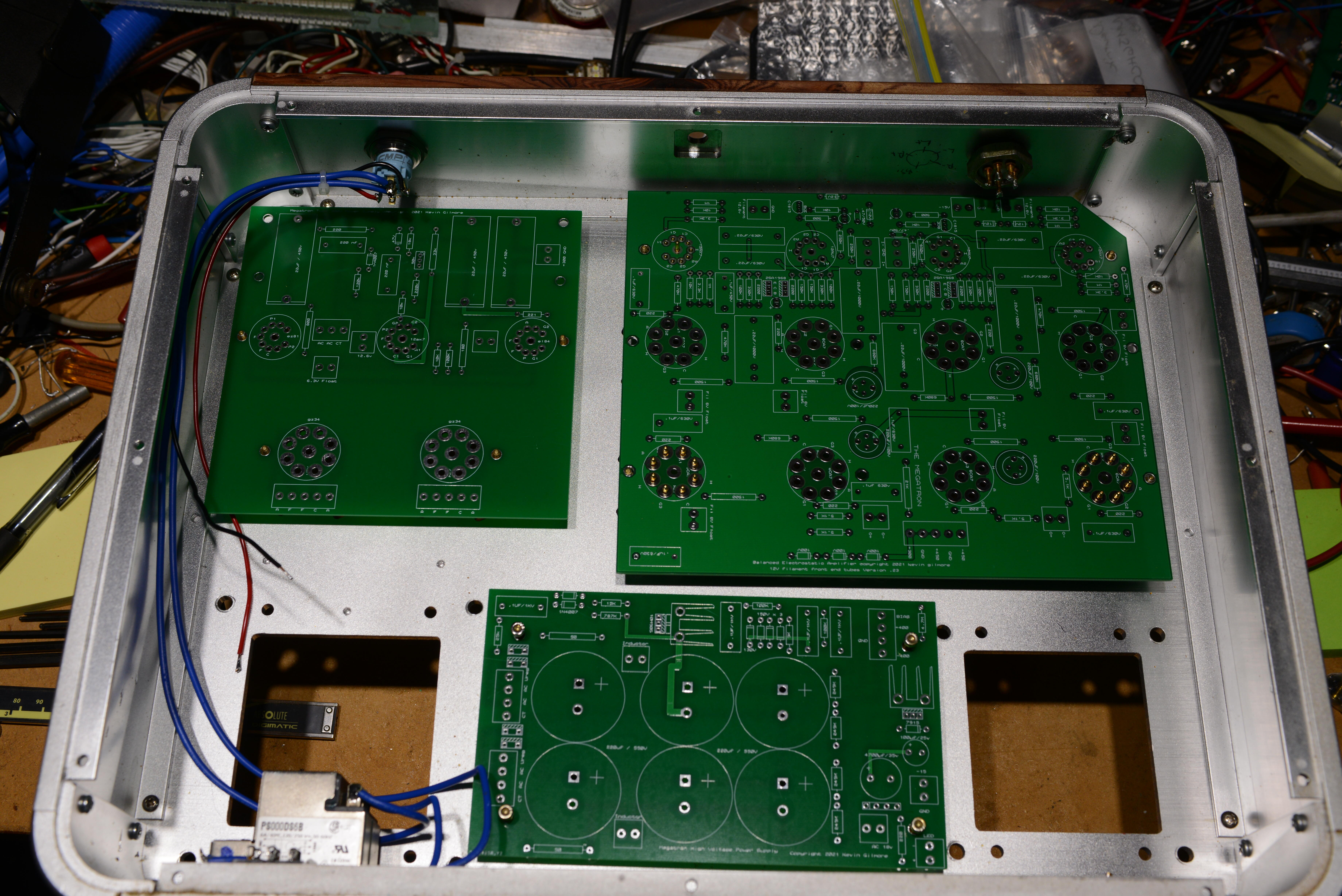
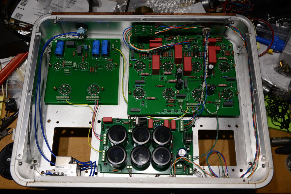
actually that plaque was a structural element that held the 300v board in. You can see the extra mounting holes on the new circuit board. But its way more than stiff enough without the extra 4 holes, so it can be flipped and re-engraved if necessary, but the screws won't be countersunk unless its re-machined. sounds like too much work for what is going to be a joke. birgir probably knows what i'm gonna do, but he better not tell. notice that all the 9 pin tubes do not have countersunk mounting holes. Also way to hard to fix.
-
i'm planning on a special modification with a label maker.
-
everything done as much as possible till the transformers get here.
-
more parts stuffage the wire used to hook up the power led inside the switch is pure silver wire from the US military in 1965. the rest of the wiring will be silver plated copper teflon.
-
progress continues
-
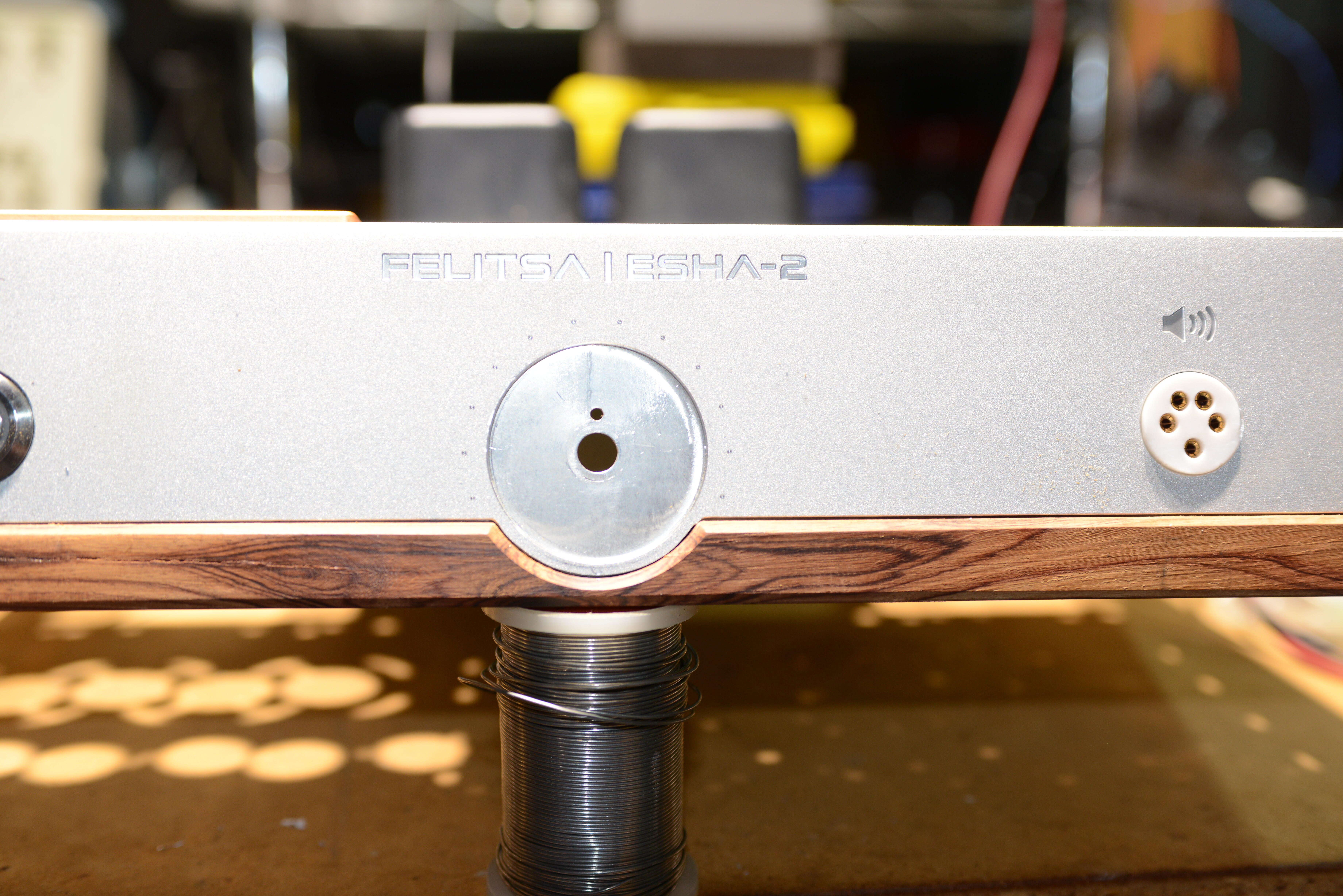
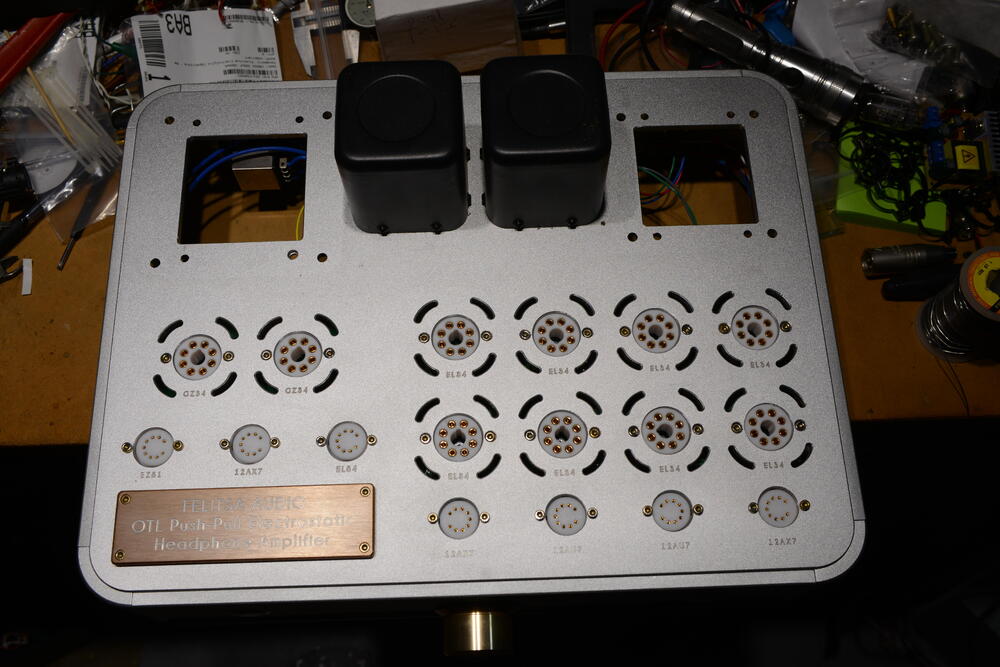
So more than 30 minutes to disassemble the front panel, 10 minutes to get it aligned into my emco fb5, and 10 seconds to put in a fucking hole that should have been there from the start. Notice the fucked up stax jack and the shitty finishing on the wood.

-
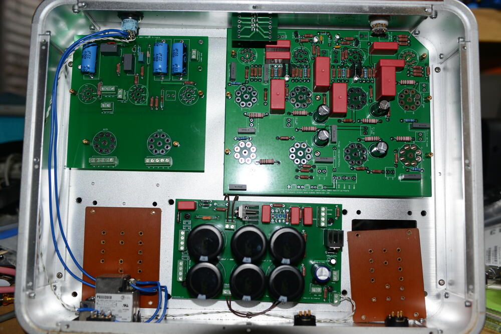
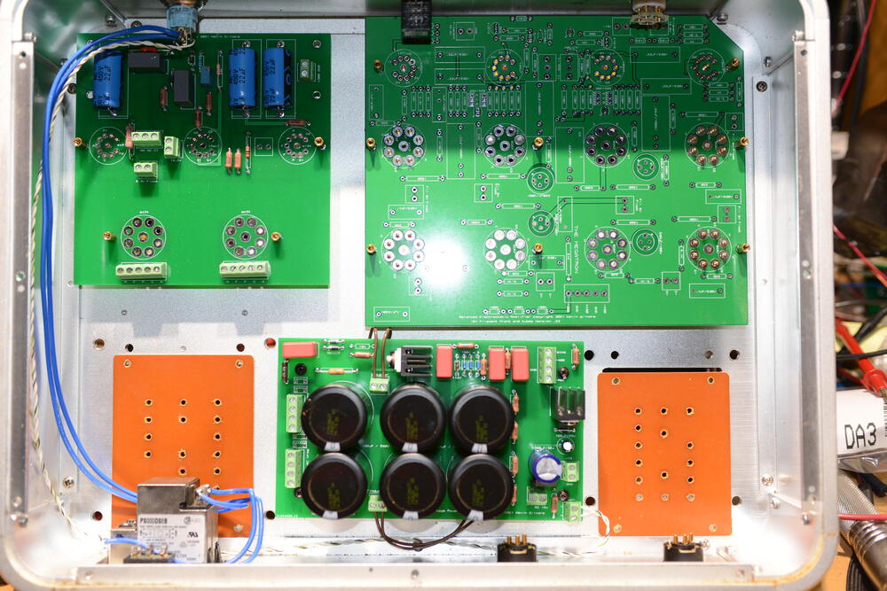
this is a put together chassis of a specific size. where he bought the chassis i do not know, but it completely comes apart, all 4 sides, the round corner pieces etc. Then he had the front,back and top all machined. all panels are .2 inch thick. And the front wood piece is esentially a stick on made of unknown wood. absolutely every single thing about this is fucked to the max. broke the anti-spin pin off the pot and did not even bother to drill a single hole to prevent the pot from spinning. Some of the work was definitely done by an nc mill, and a really shitty one at that. on the mill i used, everything was accurate to .00001 inch, and it really was at least this accurate. this thing is barely accurate to .008 inch. nothing on either inch or metric boundaries. and the holes for the power supply board were drilled by hand, and blind tapped, 2 of the 4 holes went all the way thru the panel. But the worst is the way under-rated power transformers which were potted with definitely the wrong stuff. And wiring all the filaments together. And the stax jack it turns out is also massively fucked. And force held in with rubber o-rings. Gold plated hex screws with the gold coming off. And the tube sockets were really low quality garbage, as bad as the russian crap that mikhail used. The 3 boards from jlcpcb were a total of $65 with shipping. and shipping was half the price. The hand dremel tooled boards were so utterly fucked, no reason for any of this. Somebody really high on really bad drugs did this. Not even mikhail or mike bean (hennyo) could do something so utterly and completely fucked. Wow, i gave hennyo a compliment, yikes. The 300v tube supply is actually pretty clever and kind of unique, but also utterly fucked because he had the pass tube cathode wired to ground when it had to be connected to 300v. And the bias supply with a 100k series resistor. Guaranteed to kill your headphones. Its not my money going into this, so i will continue till its either completely finished and working or the tube diode power supply cannot be made to work. Looks like the repair price will be about $1500 in parts, plus the original purchase price of about $5k. All the improvements to the amp board are in the new board. There are places for solid state diodes on the power supply just in case. There is no reason for any of this. So far i have about 30 hours of labor in this. The mikhail es1 ended up about 50 hours of labor. Yes i'm fucking nuts. all you have to do is take my board files, have them made, stuff with parts, slap into chassis. how fucking hard can it be.
-
my board does not have the delay cap. really does not need it since its going to wait for all the voltages to be within range to connect the relay.
-
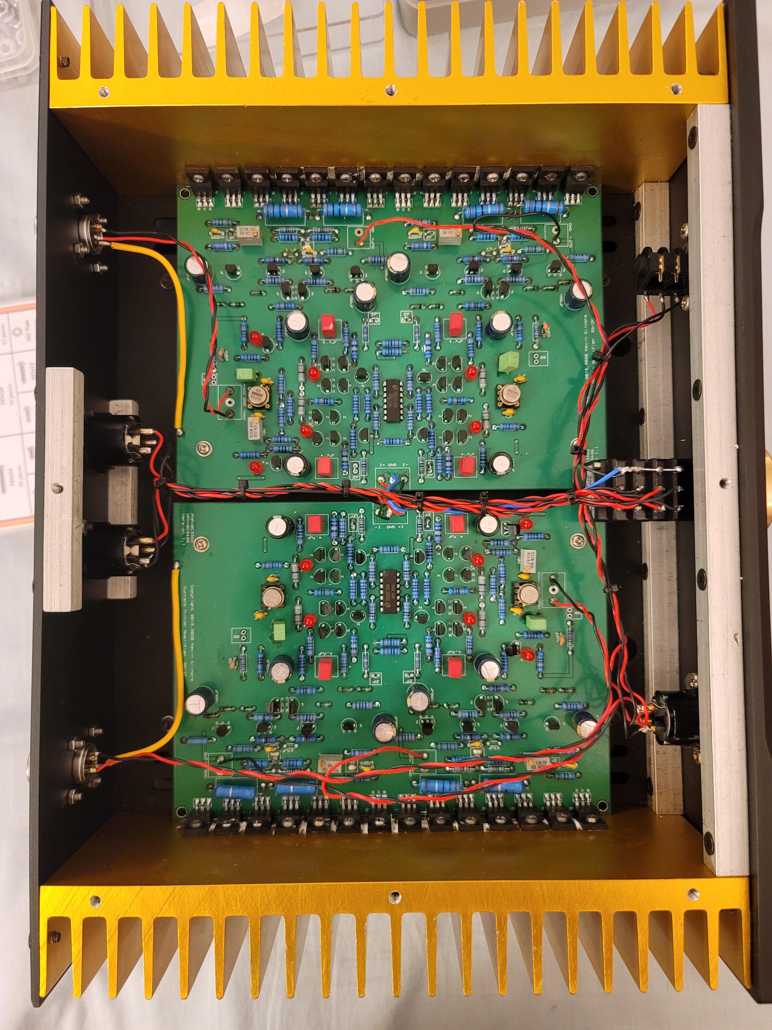
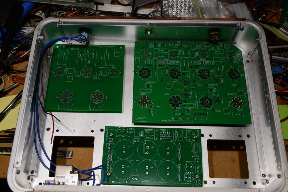
boards actually fit. well shit.
-
https://drive.google.com/drive/folders/1r3g2TAtBUaBdiMorTWX7yYgeJ7maQbYW?usp=sharing
-
https://drive.google.com/drive/folders/0B7egryukiT7_TFlEQlBRejdVdDQ?resourcekey=0-nGWwBYQ_Uivj-ciBLYMeaA&usp=sharing