kevin gilmore
-
Posts
7,204 -
Joined
-
Last visited
-
Days Won
21
Content Type
Profiles
Forums
Events
Everything posted by kevin gilmore
-

Megatron Electrostatic Headphone Amplifier
kevin gilmore replied to kevin gilmore's topic in Do It Yourself
yep, a trim pin. not really necessary unless someone comes up with a reason. all parts on order. -
Megatron Electrostatic Headphone Amplifier
kevin gilmore replied to kevin gilmore's topic in Do It Yourself
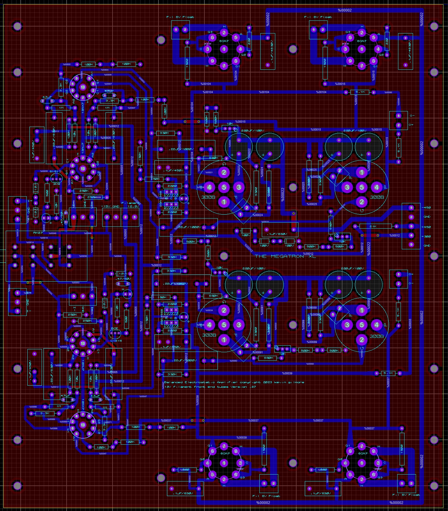
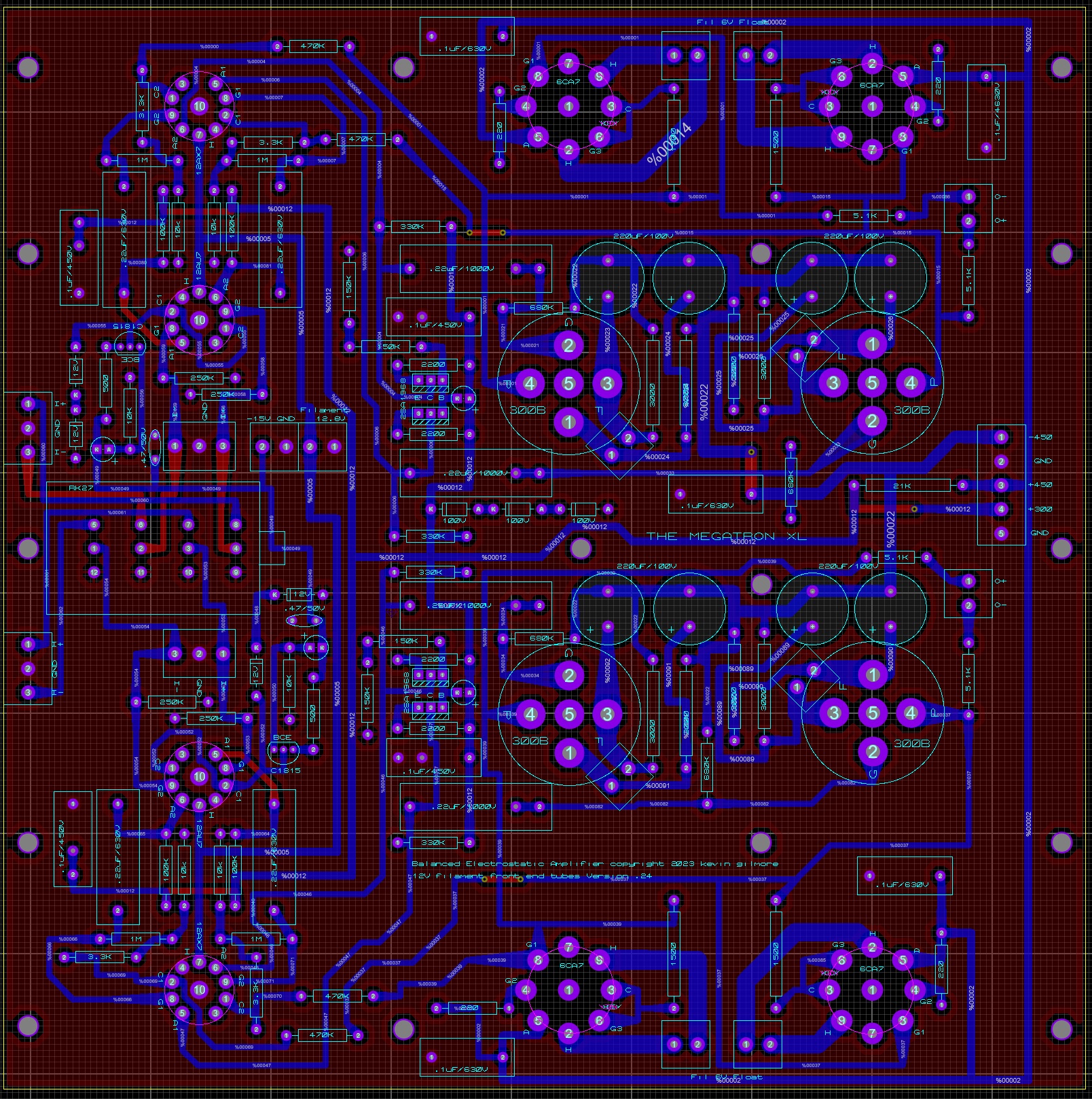
had to make the board bigger because of the diameter of the 300B pictures not same size (major squares are 1 inch)
-
Megatron Electrostatic Headphone Amplifier
kevin gilmore replied to kevin gilmore's topic in Do It Yourself
that section runs on 300 volts. ksa1156 is in stock at mouser now. would work fine. i think the pinout is backwards from 2sa1968 so just rotate it around. the emission labs tube with the octal base and the center tap filament would make things much easier but would limit the amp to those tubes. so its the standard 4 pin socket. -
Megatron Electrostatic Headphone Amplifier
kevin gilmore replied to kevin gilmore's topic in Do It Yourself
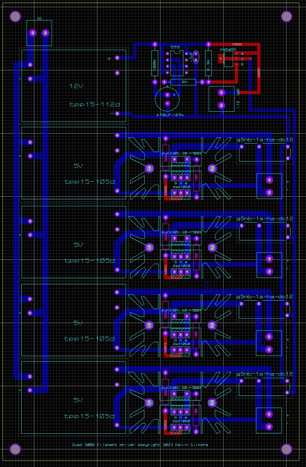
so i posted this elsewhere because people really want to spend large amounts of money on an electrostatic amplifier that uses a pile of 300b. this is the first of two. Megatron xl with 4 x 300b Megatron xxl with 8 x 300b Power supply #1 goldenreferencehv all solid state Power supply #2 tube rectified lc filtered no regulation solid state regulated bias. Power supply #3 tube rectified lc filtered 4 x 6l6gc fully regulated voltages. 300 volt tube rectified and 6bq5 regulated power supply. solid state regulated bias high voltage rectifier tubes are gz34 (5ar4) 300v rectifier tube is ez81 I figure a megatronxxl with power supply #3 should come in at a retail built price of $40k evidently one or more companies are making dc supplies that slam 7 amps into cold 300b resulting in tubes that don't last very long. so this will have a slow start quad 5v power supply board. the xxl will have 2 of these boards. amp chassis will be about 14 x 14 x 4 inches. power supply box should be the same size. the spice simulations indicate that minimum distortion is set at about 33ma, so this is likely to eat about 300 watts total power consumption. distortion will end up about .01% at full voltage swing.
-
buy whatever you can find that is the right voltage and meets minimum current requirements. bonus if it fits the original holes. otherwise remove old studs, drill new holes etc..
-
use something round and small diameter to push the piston down, then tiny long nose pliers to extract the o-ring. then size appropriately from a selection of o-rings and reassemble the same way.
-
pics of the unreplaceable o-ring please.
-
The problem with the Woo Audio 3ES
kevin gilmore replied to spritzer's topic in Headphone Amplification
the owners of ray samuels audio will say their amp is the best. just ask them. my favorites are 1) rudistor with the silver wire enhancement 2) singlepower es2 with the all tube regulated power supply 3) felista megatron. definitely you are a moron. torus? you mean tuchas. and you must have a really big one. -
and now for something completely different part 3
kevin gilmore replied to kevin gilmore's topic in Do It Yourself
100 watts maximum for those speakers! -
and now for something completely different part 3
kevin gilmore replied to kevin gilmore's topic in Do It Yourself
there is (or at least should be) a board for the rk27 pot. -
and now for something completely different part 3
kevin gilmore replied to kevin gilmore's topic in Do It Yourself
you may be the first person to test these boards. but if you have music, highly likely that everything works right. if the dac has a significant dc offset, that may cause trouble. maybe wiring of the pot is wrong? edit: 10k pot highly recommended with the that340 chips. 50k is not going to perform well. -
The problem with the Woo Audio 3ES
kevin gilmore replied to spritzer's topic in Headphone Amplification
so that is what new math actually is. -
a short in that place is definitely going to cause trouble.
-
i thought the viva was all about bling.
-
the pictures show that the inputs are line level. and its tubes. so likely push pull transformer output. for the price, can't touch it.
-
The problem with the Woo Audio 3ES
kevin gilmore replied to spritzer's topic in Headphone Amplification
I did. He confirmed it’s not a 300B output. He said the 300B isn’t powerful enough so it needed a Mosfat for the output, but I’m not really sure what that means. reference: CanJam NYC 2023 Impressions Thread (February 25-26, 2023) | Page 16 | Headphone Reviews and Discussion - Head-Fi.org so lets be specific 1) mosfet for output. lets rephrase that. 4 x apex class C high voltage power opamps. 2) 300B not powerful enough? pair of tubes is good for 18 watts. more than enough to damage your hearing. All of my tube designs that use el34 you can substitute emission labs 300b. with an adapter and extra filament transformers. Works great. plenty of power. including bh, gg, t2 and megatron. and justin's grand cayman. just because jack does not know how to correctly design amplifiers with 300b...- 58 replies
-
- 10
-

-

-

-
this is what happens if the offset pot is out of range. much easier if you have 2 voltmeters.
-
you need the inputs to ground or pot to zero. balance is o+ to o- offset is either to ground. repeat a couple of times.
-
The problem with the Woo Audio 3ES
kevin gilmore replied to spritzer's topic in Headphone Amplification
this is how it is already done. the headphones are balanced drive only. -
The problem with the Woo Audio 3ES
kevin gilmore replied to spritzer's topic in Headphone Amplification
are you so clueless that you cannot read a datasheet. the apex opamp used in the woo is a class C device. with 450v power supply rails. so loud and horrible. the apex opamp used in the d10 is a class a/b device with 175v power supply rails. so too quiet for most people. -
Background noise from headamp aristaeus
kevin gilmore replied to qqiao's topic in Headphone Amplification
you cannot correctly setup this amp by measuring these voltages. you need a signal generator and a scope. leave the phase splitter adjustment alone and set the output plate voltages to about 320v. but this is only approximate. what you want for the output tubes is maximum peak to peak voltage with symmetrical clipping. what you want for the phase splitter is balanced peak to peak voltages between the 2 output tubes. -
The problem with the Woo Audio 3ES
kevin gilmore replied to spritzer's topic in Headphone Amplification
here is another koss circuit. this one seems built better.
-
The problem with the Woo Audio 3ES
kevin gilmore replied to spritzer's topic in Headphone Amplification
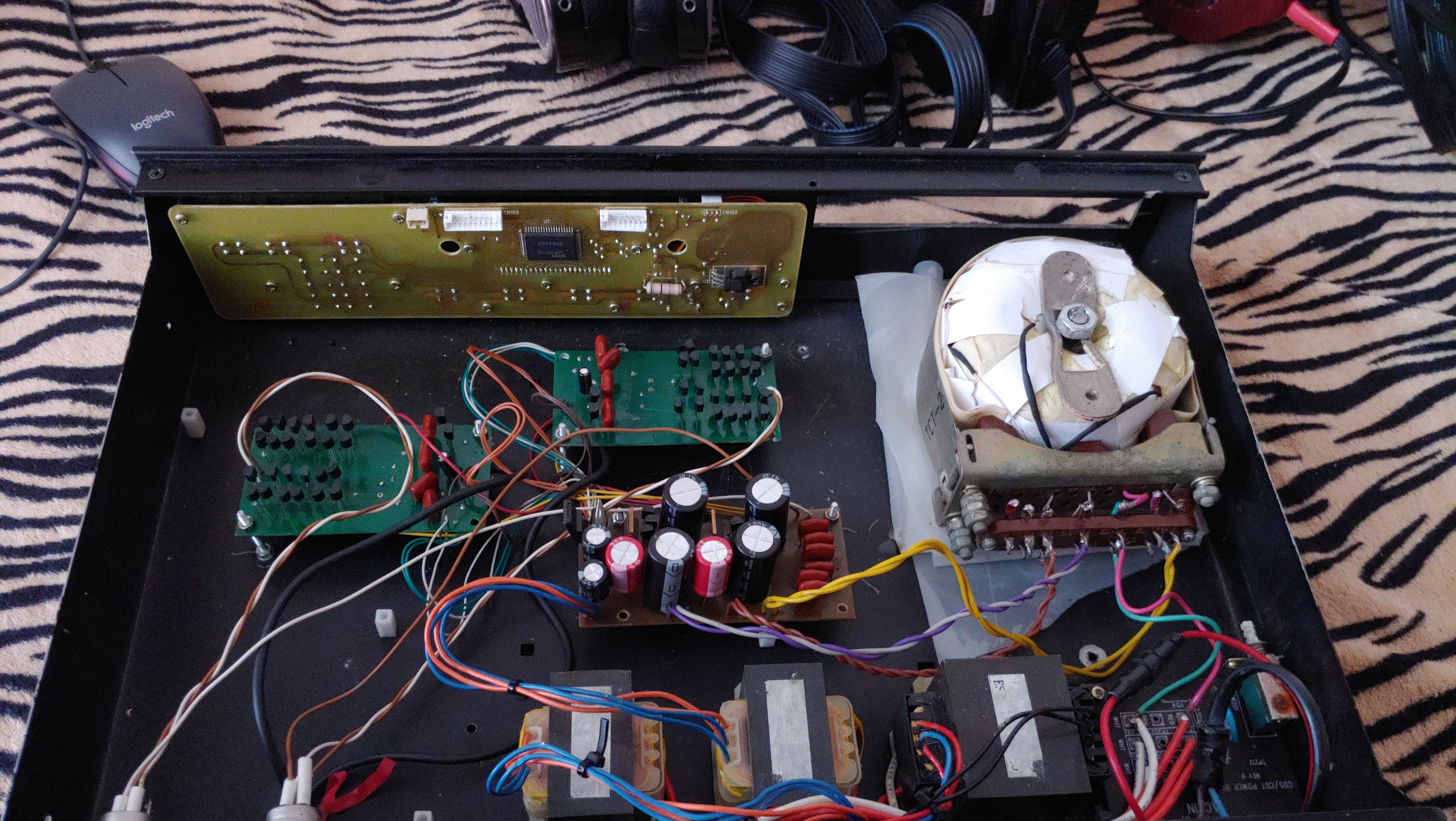
you mean like this there was another koss circuit on ebay from a guy in ukrane, i did not save that picture. it was even worse. the soviet era toroid transformer is a real gem.
-
The problem with the Woo Audio 3ES
kevin gilmore replied to spritzer's topic in Headphone Amplification
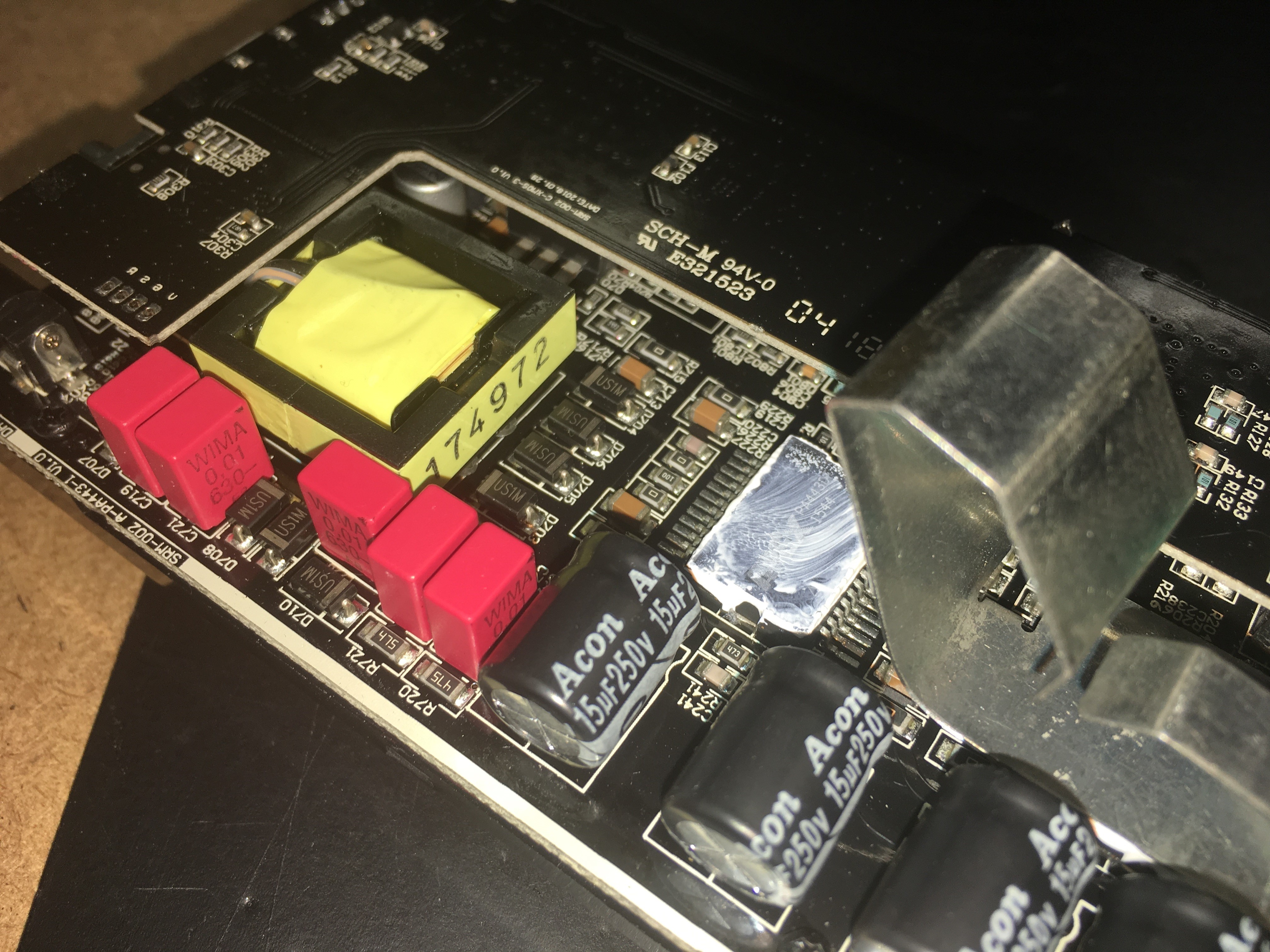
here you go pa443D
-
Repair and restoration of my STAX SRA-12S
kevin gilmore replied to Quad's topic in Headphone Amplification
jumper connector pins 7 and 8 of the phono board connector. but really it should work fine with the board removed.