kevin gilmore
High Rollers
-
Joined
-
Last visited
Everything posted by kevin gilmore
-
i have plenty of speed. 495hp + 640hp in the garage.
-
making larger in progress
-
oops, to3pf according to the datasheet spacing .75 inch instead of .5 inch. board is about to get bigger. or i find different transistors.
-
yup. not available at mouser, lots in stock digikey.
-
i'm trying hard not to get this to uberamp size there are wonderful t03p transistors that would be great but then the heatsink would be 8 inches high instead of 3.57
-
4 more transistors added so yep its longer.
-
going to have to buy one, have not figured out which one yet, then test. i did a uberamp with a smps, it was fine. i have a couple of lambda smps that i use for testing, absolutely dead quiet.
-
gerbers will be available after much more checking. lots and lots of editing was done. but if you really want to be first, i can arrange for gerbers to be delivered. you can do the checking before making boards. i got to hear a cfa3 driving vintage klipsch belle. stunning. also it was running stupid hot. so this will take care of all of that. should make all the raal owners real happy. (and deaf) (and fried diaphrams) connex switching power supplies recommended. a linear power supply would be very large and heavy.
-
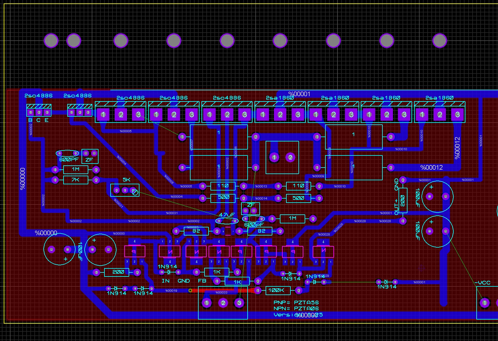
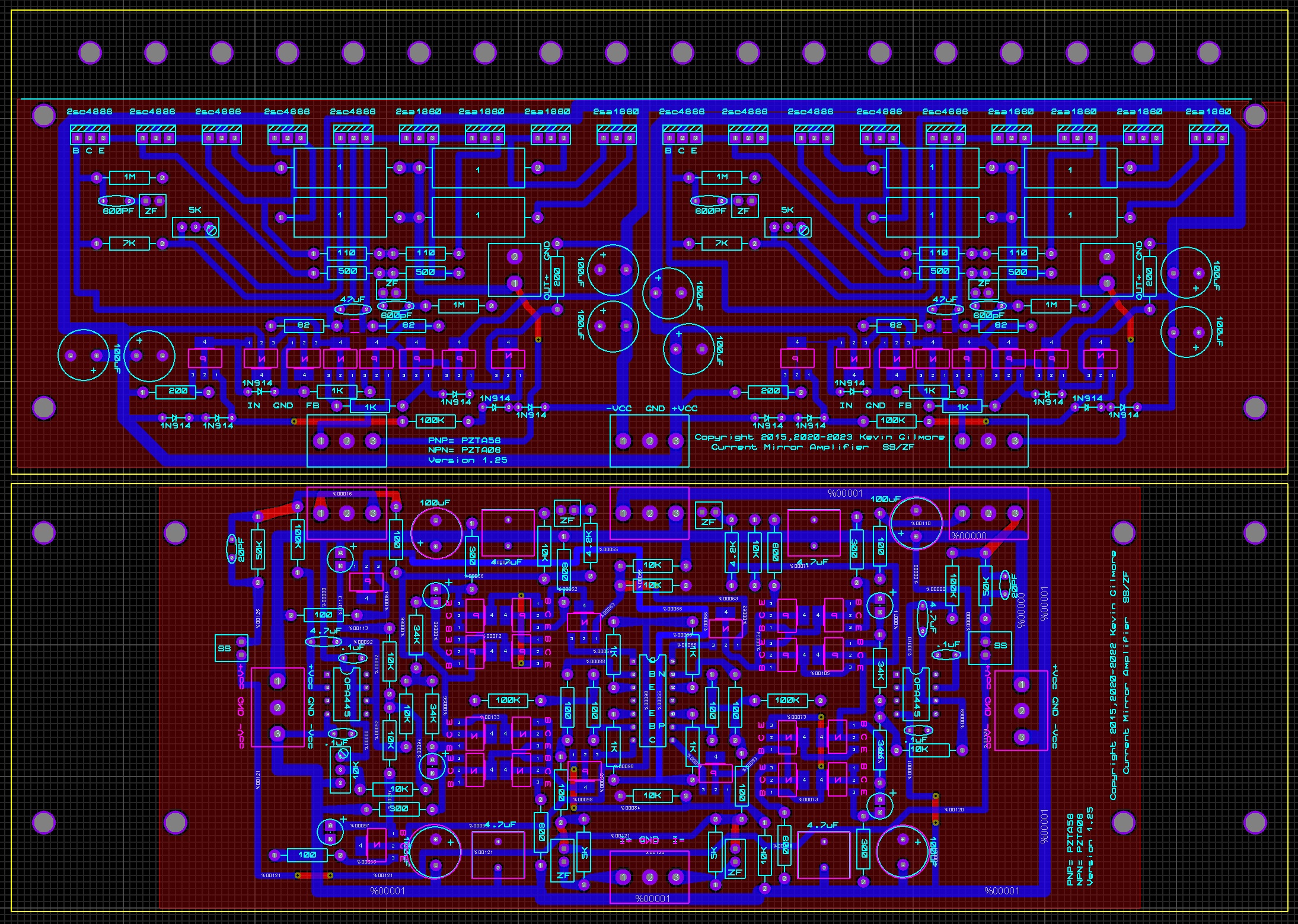
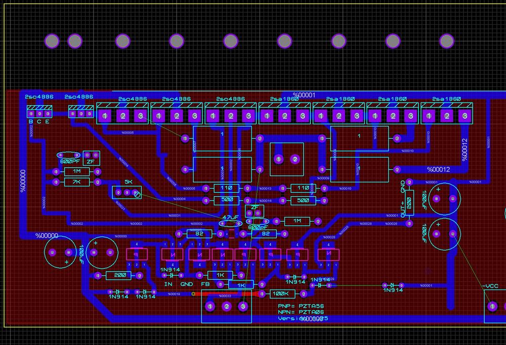
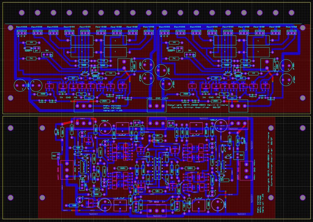
a pre turkey day new year teaser. sanken output transistors, in parallel. with appropriate switching power supplies, capable of about 25 amperes. can be built with 30v, 35v, 40v power supplies if you change out the pzta06/pzta56 with bf722/bf723 then you can go up to 60v supplies. with 40v supplies and big enough heatsinks, 100 watts rms into 8 ohms. lets see how much joamat can shrink this one. balanced output impedance, .5 ohm
-
the to243 definitely work and are the same pinout. also probably out of stock. seems like the to92 versions like to blow up in some situations.
-
that board was designed for a specific chassis. which one, i no longer remember. i could make it fit a current chassis if that is what people want.
-
keeps any dc out of the transformers. even small amounts of dc would saturate the transformers real quick. mikhail used the same circuit on the square wave instead of using a servo.
-
needed to invert the signal to the integrator. a non-inverting integrator did not have enough voltage gain.
-
-
-
this is another of the JR audio builds where they took my gerber files and reloaded them and then proceeded to do a hack job on the boards changing all the part values to R# and C# without supplying schematics, moved around a bunch of lands so that they could replace the english connectors with metric connectors, then had boards made with 1 oz copper. the +/-15 supply is of their own design with the ic's having their numbers sanded off etc. since there is no sound from either channel its likely that one or more of the power supplies is not functioning. after the felista megatron, i am DONE with trying to repair stuff that is built like this. someone with the expertise as well as a stock of required parts will be needed to fix this. many of the parts are on infinite backorder.
-
so due to a comment i made over there, someone wanted to know if i had the eddie current dht filament schematic. here it is. eddiecurrentfilament.PDF
-
no the zero feedback version does not have high loop gain. no feedback anywhere. not at the input stage and not at the output stage. first stage is a transimpedance amplifier with a output resistor that fixes the gain. output buffer is just that, voltage gain of 1 with no feedback. the feedback version bumps the gain of the input stage and adds about 5db of feedback. or whatever you set it to.
-
no, you really need that much current gain when you are doing zero feedback. especially if you like those really low distortion numbers. but sure, go ahead and modify.
-
you definitely need another cap to ground on pin 3 of the opamp.
-
sure, why not. nelson pass does the same thing with an opto isolator. i've seen various other versions of the same thing over the years, not sure why its not more popular.
-
because that is the way the original did it. certainly possible to use one pair of led's.
-
The vbe multiplier really needs to be on the heatsink otherwise thermal runaway may happen.
-
put a 1.5v battery on the input, and cycle thru the steps and watch the output voltage.
-
dc filament power supplies normally cause way more trouble than they fix. and you definitely want that supply floating and leave in the 47 ohm resistors.