kevin gilmore
High Rollers
-
Joined
-
Last visited
Everything posted by kevin gilmore
-
magni, magni2, magni2uber, jotunheim,liquid carbon, and the new headroom amplifier. None of these things have heatsinks of any kind on the output transistors and thermal stability is questionable, and then they overheat, and long term reliability is non-existant. there is a reason why you are supposed to put the thermal compensation diodes as close as possible to the output devices. Same problem with the singlepower squarewave but a bit more dramatic.
-
attach the pass transistors to short wires its done a lot more often than you think on big expensive instruments
-
it could certainly be balanced susy. biggest question is what to use for output transistors
-
you are going to need to be able to fix the blue and orange wires and attach them back to the circuit board
-
I have never listened to the yggy, and likely never will. No DSD! The amps are all designs from the 70's and sound like it too. hard to tell which is worse, jotunheim or liquid carbon. Both have the same failure modes.
-
I don't stoop that low either. I have 4 pieces of schiit. The joutunheim broke me. That's not a piece of schiit, its a piece of shit. you can't leave it on for more than about 8 hours, it starts to cook.
-
I can certainly do a new board, it would have to be mostly surface mount, and different output fets. I can definitely see that running the board without the main electrolytics would effect the low frequencies
-
The push pull is still pure class A so in theory the Sonoma at the same bias would be half the power as long as the voltage swings are similar
-
So balanced electrostats have a linear response with respect to the amount of movement of the diaphragm vs voltage. That is because the dual non-linearities of each stator balance out the position of the diaphragm with respect to voltage. single ended electrostatics do not do this. So higher voltage swings result in more distortion than lower voltage swings. pretty much an exponential curve. throwing piles of dsp at the problem likely only fixes some of the problems, and then is subject to temperature and humidity of the room. The only known version of this that was ever successful was the beveridge loudspeaker. And the acoustic lens allowed for very small movements in the diaphragm to generate substantial sound levels. Which is what happens when the diaphragm is 6 feet x 1 foot. this is going to be epic fail.
-
kgsshvcarbonv5.pdf goldenreferencehvsic.PDF megatron.PDF added megatron schematic
-
schematics t2schem.PDF t2schempower.PDF
-
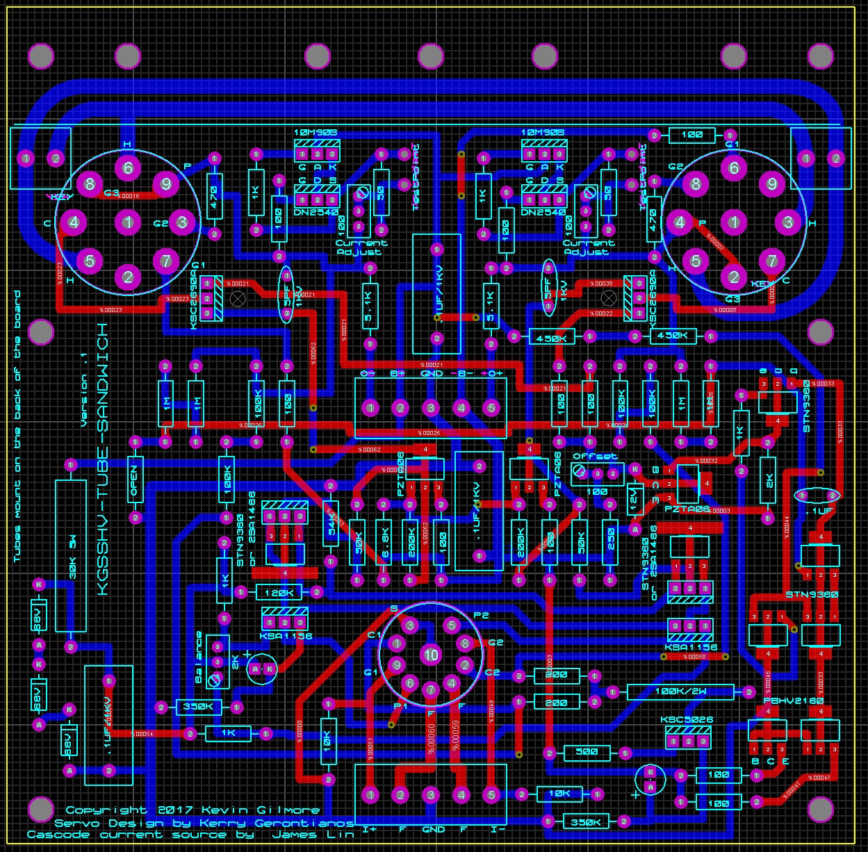
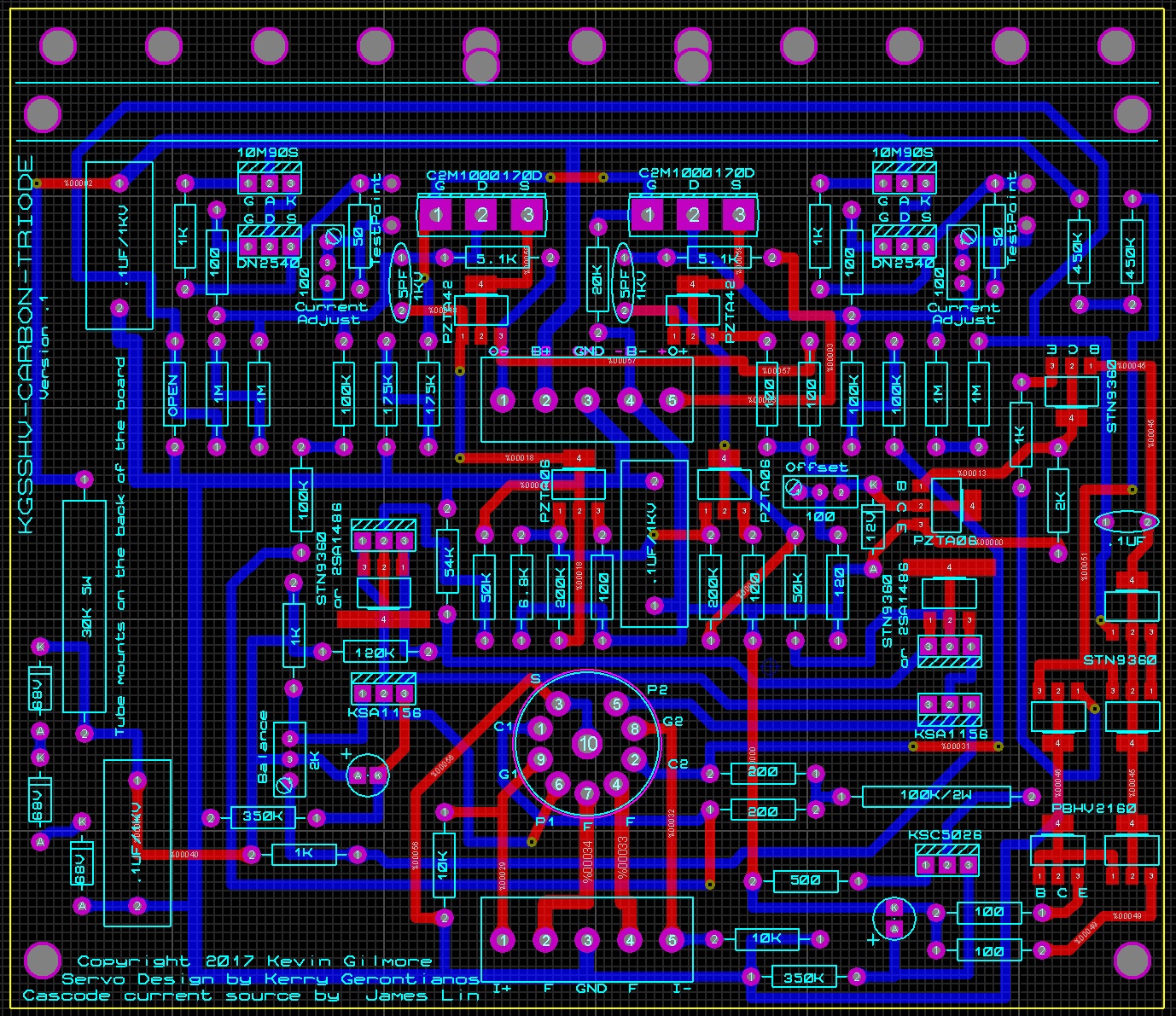
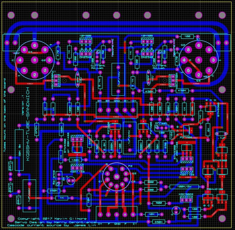
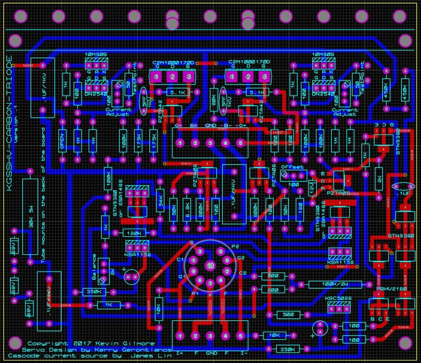
todd added zip files to the attach list, so please look at these and see if I made any mistakes kgsshvcarbontriode.zip kgsshvtubesandwich.zip
-
length or width, you are asking for width. for that box, inside is 6.3 x 11.8 so two amp boards would fit on one heatsink already. no room for anything else, would have to be a two box. I centered everything on the board, so when you put them next to each other, the tubes align.
-
updated the board pictures, either stn9360 or 2sa1486 (people should have bunches of them, still available) that transistor is roughly .6 watt 5 watt resistor is designed to give about 200v 3 x 68v zener in series would be around 210, so if the tube is not warm...
-
they are not the same kind of plugin's that fit in the 7000 series scopes. but they are plugins that require a power chassis.
-
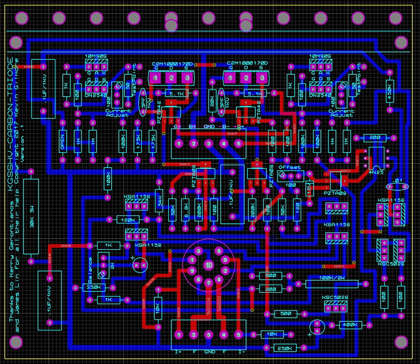
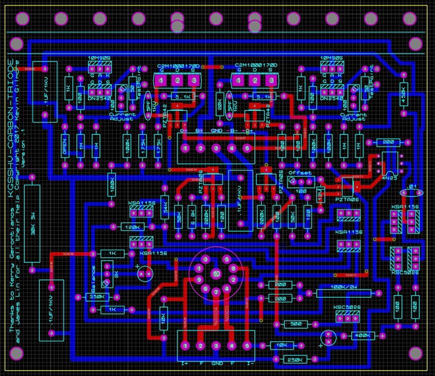
Kerry needs to publish the latest schematic with his servo. posted version does not have enough current to drive the opto. would still work without the servo
-
actually the cathode sits at +1.5 volts, very similar to T2.
-
not to scale, carbon board is 5.45 x 4.72, tube output board is 5.6 x 5.52 newest versions of the boards
-
one capacitor in the audio path.
-
well that is one way to make a fully dc coupled megatron
-
looks like the best I can do is about 5.7 inches current gg board is 4.7 inches
-
that's enough for today
-
using Kerry's servo, but a resistor to make +200 by the way the alternate name of this board will be t8000DR (DR as in done right) edit: fixed font sizes
-
18 to 20ma guitar amps will bias them much more, but they run at only 400v total
-
i'm not sure what the mjw18020 is designed for, but for dc use, its going to blow up over 450v