

kevin gilmore
High Rollers
-
Joined
-
Last visited
Everything posted by kevin gilmore
-
the rest of the power in the circlotron is pure AC for the filaments, so not much of a turn on whoosh either
-
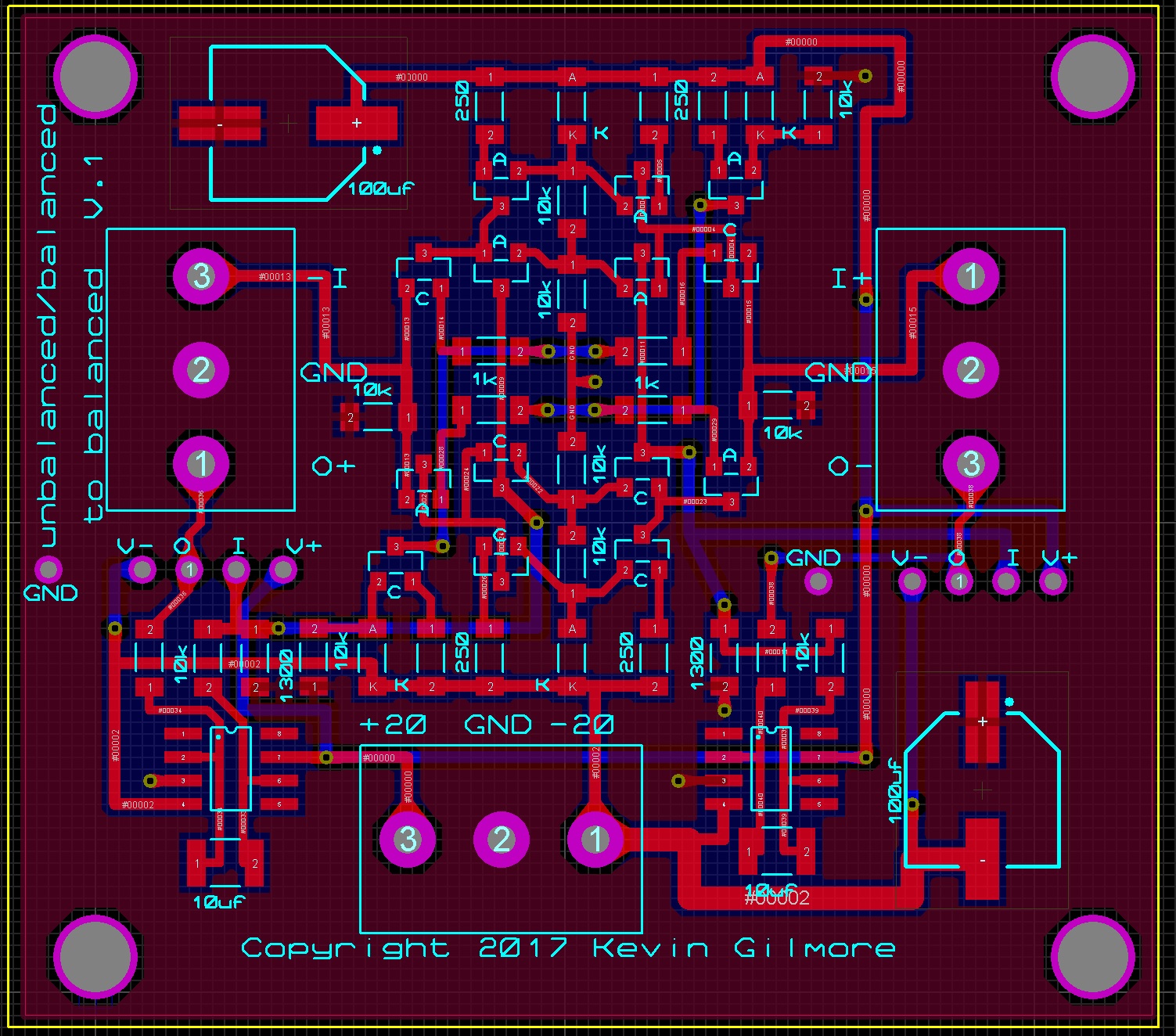
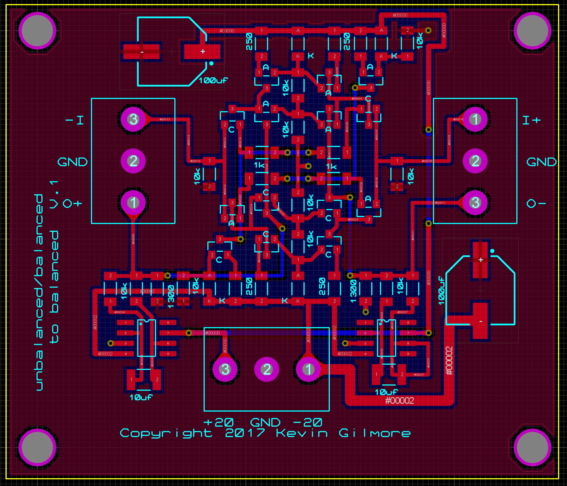
the way the board is layed out currently its really input -> attenuator -> ubal/bal -> diamond buffer because there is only one set of servo's and the attenuator is best at something like 10K
-
unbalanced to unbalanced, gain of 1 unbalanced to balanced, gain of 2 etc you can adjust the gain by changing the 1300 ohm resistors, or the emitter resistors up to 10x is possible with no increase in distortion these days, I don't think there is any reason to add much gain
-
remember that there is both a dynamic and electrostatic current feedback amp. using the bh power supply on the dynamic amp is going to result in much magic smoke.
-
deleted
-
final dns change monday morning machine will end up on 165.124.198.148 and dns will change a few hours after that 2/1/17 edit, final networking address, should stay this way till i retire
-
highest hfe, make sure to match hfe and vbe
-
i have not touched that one in a while. don't see any reason to, i like it the way it is
-
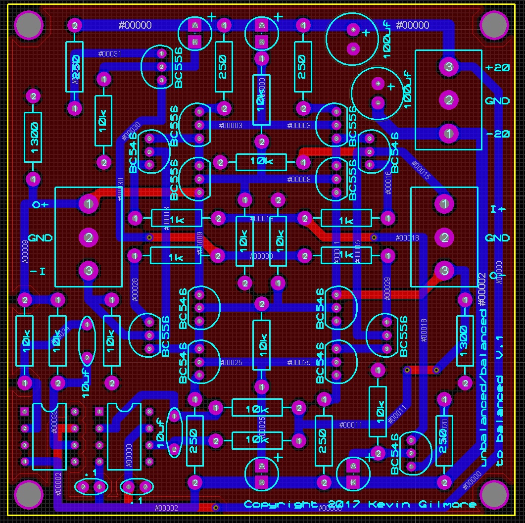
transistors are 2sc3324 and 2sa1312
-
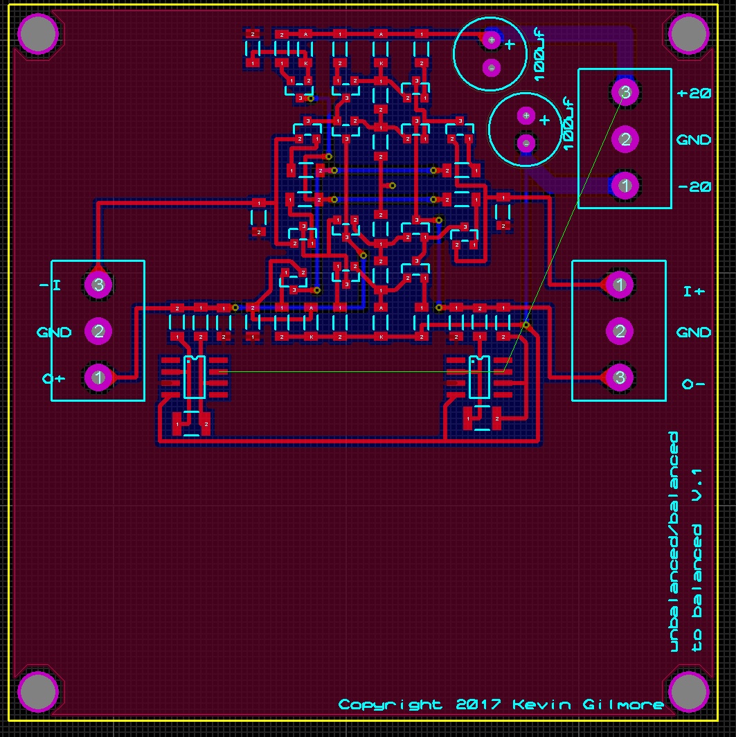
posted final smt version of the ubal to bal board. the smt boards should be cheap because they are tiny, ubal board is 2.42 x 2.12 and the diamond buffer is 1.46 x .8 I would like 4 of the ubal boards, and 8 of the diamond buffer boards please
-
that was not a buffer. that was a 60 watt + power amp done with semisouth as output devices.. It was pretty nice for a small chip amp.
-
probably close to final 2.45 x 2.17 inch

-
lm49830 is a chip amp do you mean opa1632 and its clones, all of which require huge amounts of feedback and have all sorts of common mode dc issues
-
diamond buffers will stand vertical on that board. there are thru hole versions of both pieces already
-
moar better 2.65 x 2.27 inch

-
some people are going to have trouble assembling this, same size for comparison see updated picture belowcorrectyep, gets the output impedance down to say 5 ohms. then you can add some resistance to match the cables you intend on using, +45 or +70 ohmsfor soren, thru hole version with servo
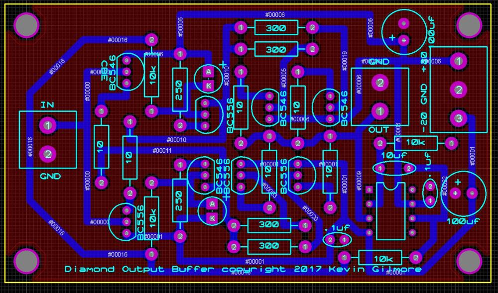 start laying out your own boards and you will know why. there will be a all smd version at some point with these as output buffers .8 x 1.5 inch
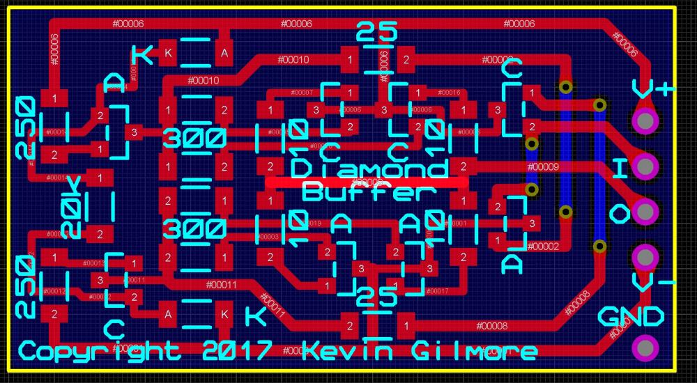 it had better look like this the output impedance is about 1k, working on the diamond buffer output now
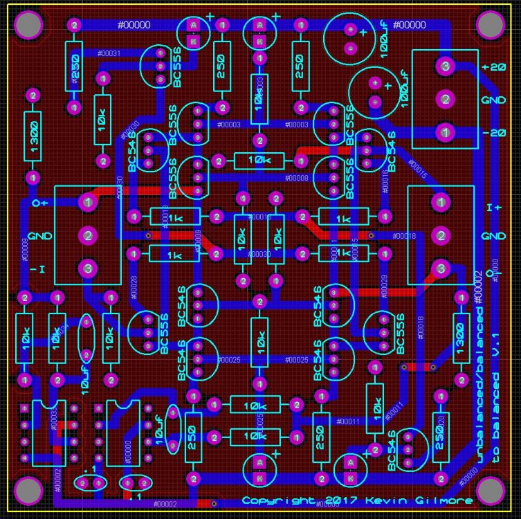 boards at the speed of light. updated version of the board with input resistors just posted. by adjusting a few resistors you can get up to 6db (12db balanced) gainno no no, swimming pool, it floats


Important Information
By using this site, you agree to our Terms of Use.