


sbelyo
-
Posts
1,036 -
Joined
-
Last visited
-
Days Won
1
Content Type
Profiles
Forums
Events
Posts posted by sbelyo
-
-
This was the best source for them for me
https://www.amazon.com/gp/product/B0756KLNLX/ref=ppx_yo_dt_b_asin_title_o01_s01?ie=UTF8&psc=1
-
-
Can anyone recommend a free gerber viewer that lets you print the layers true to size? Or at lease view them on screen where they're accurate enough for measurement.
-
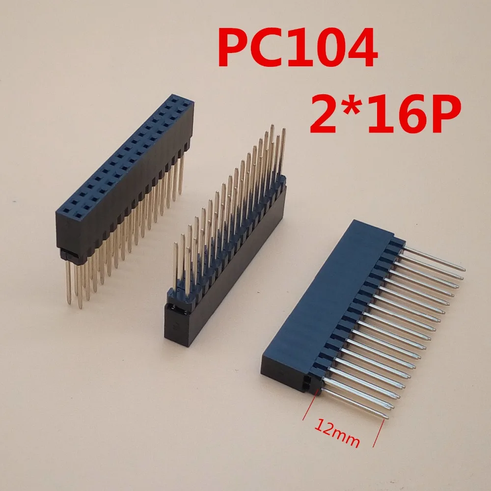
I need help finding board stacking headers like these. I need to stack a bunch of Arduino shields and a screen together. I can't seem to find them on mouser or digikey but thats probably me not putting in the right info


-
 1
1
-
-
At first glance and a quick measurement from the bottom, the hole seems to be dead center. I will print out the outlines this weekend and see where it matches up
-
I've done the same. But I totally get where purk is coming from.
-
All of my headphone's have been terminated or re-terminated with a 4 pin xlr for years now
-
transformers should be here tomorrow
-
Max for length is 228.5 mm
-
9 hours ago, n_maher said:
If adding features to the board might I suggest a fuse? Not sure if this is a one-off and not worth bothering, but sometimes a chassis just doesn't lend itself to the somewhat monstrous integrated IECs that have both voltage switching and fuse provisions. That's what made me think of it anyway.
For me it'd be cool to do the voltage switch. I have enough room for an IEC inlet with a fuse. Let me measure to see how long the board can be
7 hours ago, kevin gilmore said:if you rotate the left transformer 180 degrees, makes the high voltage wires a lot shorter.
My only thinking was to have AC in on the left so the wires are very short to the front panel switch and then the secondaries are facing the AC in on the PSU boards. Basically just keeping the wiring as short and neat as possible. Is that creating more of a problem with noise the way it is?
-
That switch is cool, I like that
-
looks good. I expect the transformers next week so I'll measure that to check. Unless someone here has one
-
3 minutes ago, Pars said:
Maybe just put a voltage select switch right on the board as well, and only have 2 AC in (L/N)?
EDIT: Also note that the 35VA/50VA trans use 1.3 mm pins, larger than the others.
That would be cool... It looks like the outer holes are bigger so I think that's ok.
-
This look really good! I should have some 50VA coming next week. I don't have any 25VA, let me see if one is in stock
-
1 hour ago, jamesmking said:
ok working on it. I have done the 25va transformer (I think. I assume you would like the 35 and 50va on the same pcb if possible.
yep that's right. If you have to drop one to make it fir you can cut out the 35. I really only need the 25 and 50VA
-
I wasn't sure how to draw the traces. I figure leave the primary and secondary alone so anyone and choose 115 or 230 on the primary and parallel or series on the output
-
Ok, excuse my crude drawing but this is my idea for a basic dual side by side layout. The AC in and out would just be the normal terminal block we all use. 5.08mm pitch with a 1.3 mm hole. I use 4-40 stand offs so the holes would be 3.26 mm or there abouts. Not sure what size hole is usually standard for that.
For the transformer pin spacing and hole size I circled the 25, 35, and 50 VA models, the specs are in the chart. I was looking to do those three. Let me know what you think.
-
sure, let me get cracking.
-
that's just what I was looking for... The 50VA is just slightly bigger unfortunately. I did order some protoboard so that's most likely what I'll use
-
Does anyone have or know where I can find a board that would let me mount a single or side by side Amveco PC mount low profile toroidial transformers? I'm just looking for a board that would have AC in and out going to terminal blocks and allow the use of standoffs.
Amveco PC mount low profile 50VA toroidial transformers https://talema.com/wp-content/uploads/datasheets/70000K-72400K.pdf
If not, I'd gladly pay someone for their time to lay out a board for me. Something like the pic in here
-
8 hours ago, swt61 said:
I believe that Amazon music let's you store your own music files in your cloud locker.
There's always the chance that I'm mistaken.
They do
At least she is using Itunes. My wife is trying to figure out how to play CD's
-
This is just sad...
-
love that movie! "How dare you make hand party with Pamela"
-
6 hours ago, Craig Sawyers said:
What is the sack for? Wotcha going to build?
It's all the parts to build a Dynalo MkII and a GRLV to power it. Stocking up for the winter build season
-
2
-


.jpg.515df83c8298d69867188424743a2a7d.jpg)


Need newb help with Arduino Due
in GoRedwings19's Computer Help Hotline
Posted
I'm looking to add an arduino to control my dac. I'm not worried so much about writing code as that's already done and proven to work for others. This whole platform is new to me. I can see that the initial scrpt or program is the .ino file and that will contain commands as well as references to libraries but I'm not sure how to put this altogether in Arduino IDE to upload it to the Arduino Due.
I purchased this display for the project
https://www.buydisplay.com/5-inch-tft-display-arduino-touch-shield-ssd1963-library-for-mega-due
There is a download with examples in it here
https://www.buydisplay.com/arduino/Libraries-Examples_ER-TFTM050-4.zip
I want to test the 480x272 demo. I see the ino file and have downloaded the UTFT library and added it to Arduino IDE.
Do I open the ino file in sketch then include the UTFT library and complile then upload? Or am I missing steps?