JimL
High Rollers
-
Joined
-
Last visited
Everything posted by JimL
-
Yes, but if you look at the diagram, there is no other stator. There is only a stator on one side - in fact they brag about the fact that there is no second stator. Perhaps the DSP is also needed to correct for that?
-
In other words, it's single ended. I wonder how they manage the distortion inherent in a single-ended device?
-
Good show.
-
Wonderful! A mod that costs twice as much as the list price of the amp and can't get rid of the current drive limitations due to limited heat sinks.
-
Well, I have a somewhat different perspective on this. I don't know that "tubes had to become more reliable into the '50s" as prior to that there was no other option. In fact, if improved reliability was a major engineering goal you would think that the tube manufacturers would be putting out advertisements touting it. They didn't. They did promote cheaper 9 pin miniature tubes, e.g. 12A_7 vs. more expensive pre-war octals such as 6SL7 and 6SN7, squeezing more elements into the same tube envelope with compactrons (less tubes, less expense), or putting in controlled filament warm up elements to allow manufacturers to run series filament heaters (less expensive) - do you see a pattern here? The fact is by the 1930s, consumer tubes would last 5-10 years, which was "good enough." In fact, the major factor for tube reliability is conservative operating conditions, which was understood in the 1930s - the longest running tube was a "Mazda AC/P pentode valve (serial No. 4418) in operation at the BBC's main Northern Ireland transmitter at Lisnagarvey. The valve was in service from 1935 until 1961 and had a recorded life of 232,592 hours." A 1930s tube. In the 1950s, they did introduce premium versions of the 6SL7 (5691) and 6SN7 (5692) tubes which were supposed to have a longer service life. The way they did that is very simple, they just derated the tube so it was supposed to run at lower voltages, currents and power dissipation than its parent tubes. Now, it is true that they made advances in reliability for specialized tubes which were used for trans-Atlantic submarine telephone cable repeaters, but AFAIK that technology never made it to consumer grade tubes - too expensive. Switching to the other item in your post, would it be possible to show the schematic of the HEV90? The working version, that is.
-
I'd say that's an oversimplification. For example, some of the triodes from the 1930s such as the 56 and 76 tubes are among the most linear tubes ever designed, as documented by Eric Barbour in issues of Vacuum Tube Valley. 6SL7 and 6SN7 tubes designed in the 30s are more measurably more clinear than theircounterpart 12AU7,6CG7 and 12AX7 tubes from the 1950s, which were primarily designed to cost less. OTOH he latter tend to have less microphonics due to smaller plate dimensions, so pluses and minuses, but not all on the later design's side. And NOS JAN (Joint Army Navy) tubes that were sold as surplus in the 1990s and 2000s when DOD finally decided that they were never going to use those old tubes are nobody's idea of "rejected crap," as they were stocked after meeting military specs. A lot of the advances in tube technology in the 1940s were due to the war effort and had more to do with VHF and UHF design for radar, not improvements in audio tube design. As for materials, probably some improvements there. Lynn Olson has noted that early direct heated triodes are measurably very linear devices, more so than even triode strapped pentodes from later. They do have disadvantages of course in terms of amplification factor, hum problems with AC heater supplies, etc. The 300B is one of the most linear tubes ever designed. Not ideal as a stat headphone amp output tube because of its voltage limitations and its relatively high current requirement for best linearity, which isn't needed for stat headphones.
-
Actually, I get what you're saying, which is that the actual cost of the thing is way under the price that is being asked for it, i.e. HUGE markup. Very unlike, say the BHSE, which a lot of manufacturers would charge a great deal more than the asking price.
-
Actually, if you read the 1939 Western Electric data sheet here: http://www.tubebooks.org/tubedata/we300a_b.pdf it says: "Classification: Moderate power filamentary triodes for class A service. Application: Audio-frequency amplifier in positions where power outputs of approximately ten watts or less are required at relatively low plate voltages." So, not transmitter tube, not Class B. Sheesh! in fact, in the 1930s, Western Electric was a major supplier of equipment to movie theaters in the U.S. They had two amplifiers that were commonly used to drive their speakers, the Model 91, which used one 300B tube as the single ended output, and the Model 86, which used two 300B output tubes push-pull. If you watch U.S. black and whilte movies from the 30s you will quite often see Western Electric credited with some aspect of the sound reproduction.
-
Um. I think it IS built in China. Now, being first generation Chinese American, I have nothing against stuff being built in China. They can build cheap junk, if that's what you're willing to pay for. Or they can build quality goods, if that's what you're willing to pay for, and have the quality control to make it happen. Seems like Dr. Bian is charging quality prices for stuff without good quality control. Well, Mikhail had the advantage of starting with a good circuit (the SRX). He just didn't know how to implement it, and his tube rolling capers screwed it up even further. JMHO.
-
Possibly, but the all-triode used 12AX7 tubes, which have 5 times the voltage gain of a 6SN7, and 6S4A output tubes, which have 4 times the voltage gain of a 300B tube. All that extra gain allowed the all-triode design to have some overall feedback to stabilize the design. With the 6SN7 and 300B tubes, there just doesn't appear to be enough voltage gain to get the overall gain needed plus a little extra to allow overall feedback. Without overall feedback the result is drift. Ah, well, Boston Symphony Hall generally has excellent acoustics - I have enjoyed several concerts there. But as I mentioned, there was one occasion in one location when the sound was like listening to speakers with blown tweeters.
-
Here's the Bell Telephone data sheet I found dated 1950: http://www.mif.pg.gda.pl/homepages/frank/sheets/084/3/300B.pdf. It says 400 volts max DC, but also shows the current-voltage curves going out to almost 700 volts. And they were designed as power output tubes to drive transformers, so I would expect them to swing AC peaks up to almost twice B+. With either resistors or current loads you would have to dissipate as much power in them as in the tubes, and with a 300B running at a typical dissipation of 20 watts (55% of max, a good conservative operating condition) that means 80 watts in the resistors or current sources - similar to a DIY T2, but with much less voltage swing. I would think even output resistors would probably need significant heatsinking.
-
Well, Chicago Symphony Hall has had its critics about its sound quality since it was renovated in 1997 - see the Wikipedia article, so who knows what he regards as "ideal" live sound. And of course, the sound of a concert hall in recording, which, except for the occasional live recording, is done with nobody in the audience, sounds different from the sound at a live concert packed with people. Live sound is actually notoriously variable. The sound in the front rows can be drastically different from the sound in the upper balcony - I remember sitting in Boston Symphony hall in the upper balcony decades ago at a concert which sounded like a muffling blanket had been placed over the whole orchestra. So, no output transformers. Input transformers maybe to boost the gain? Or current source loads on the 6SN7s to boost their gain to the max? And incidentally, I found a Bell 300B spec sheet that shows current/voltage curves to 700 volts, so it can put out about much voltage as a 6SN7GTA if properly driven - more current, though.
-
Obviously, since Stax has been making electrostatic headphones since before Dr. Fang Bian was born, they don't have a clue about, um, er, ah... Dr. Fang Bian (in Emily Litella voice): Never mind. Likely trying to push his new limited voltage output 300B stat amp with 6SN7 drivers. With those tubes, wonder how he got enough voltage gain?
-
He is the head honcho of HiFi Man.
-
Ah, but it's special audiophile-grade hot glue. Very exclusive. Very expensive. But requires the very expensive audiophile electrons with a spin of 1.
-
Well, you could start your reply: "Dear Dumbass:" But maybe that would give him a clue.
-
Ah, Old World Craftsmanship!
-
Yes, they would need to be at least 1 watt. I used the same 2 watt resistors as are used in the output stage resistor chain. The reason for doing this is to further isolate the two channels for purposes of trouble shooting, but practically, it makes no difference if the circuit is working properly. As you note, with the first run PC board you would have to cut the traces from the C- supply - I think Kevin has updated the board to the newer circuit, but that doesn't help people with the first board. I built mine point-to-point so more difficult to build but easy to modify. Circuit boards are easy to build but more difficult to mod.
-
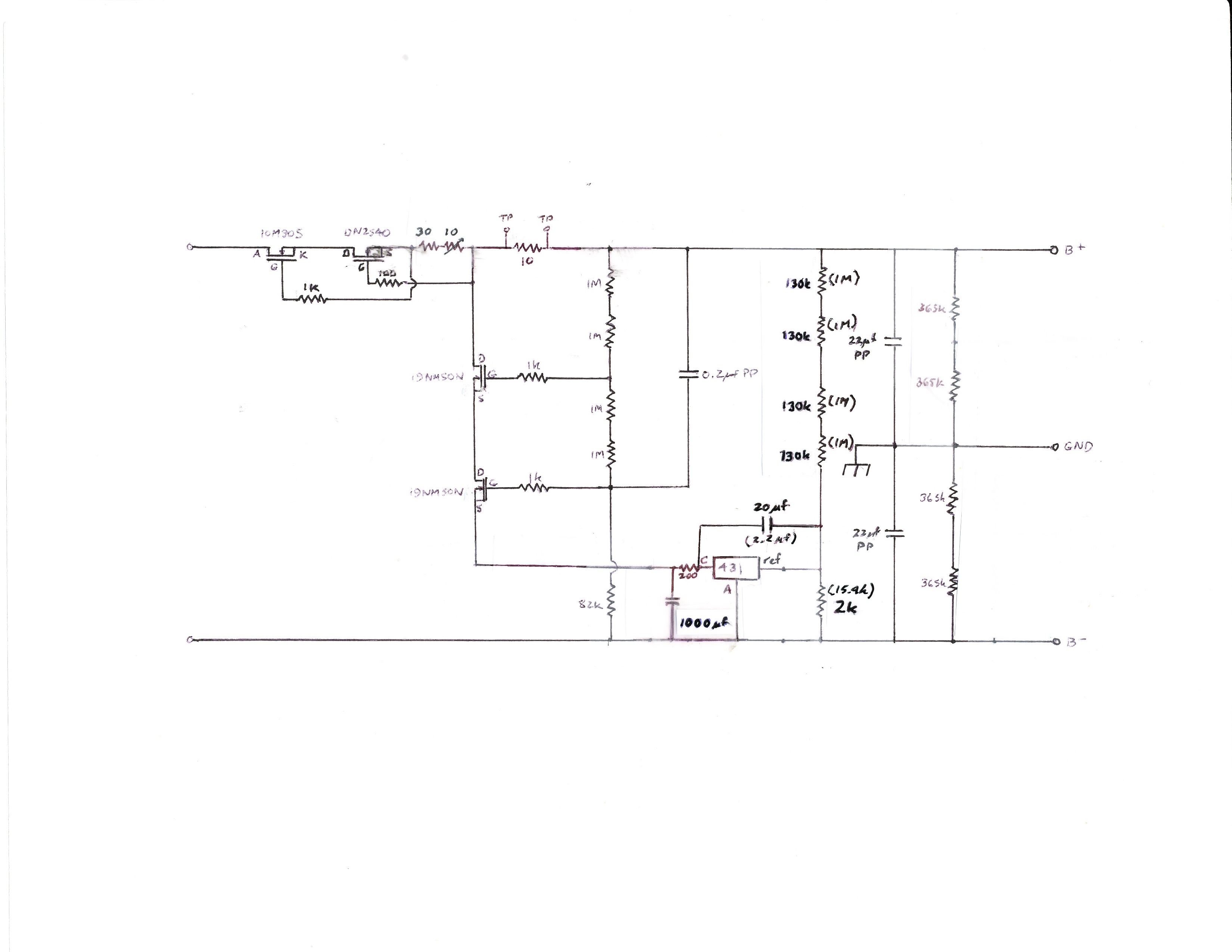
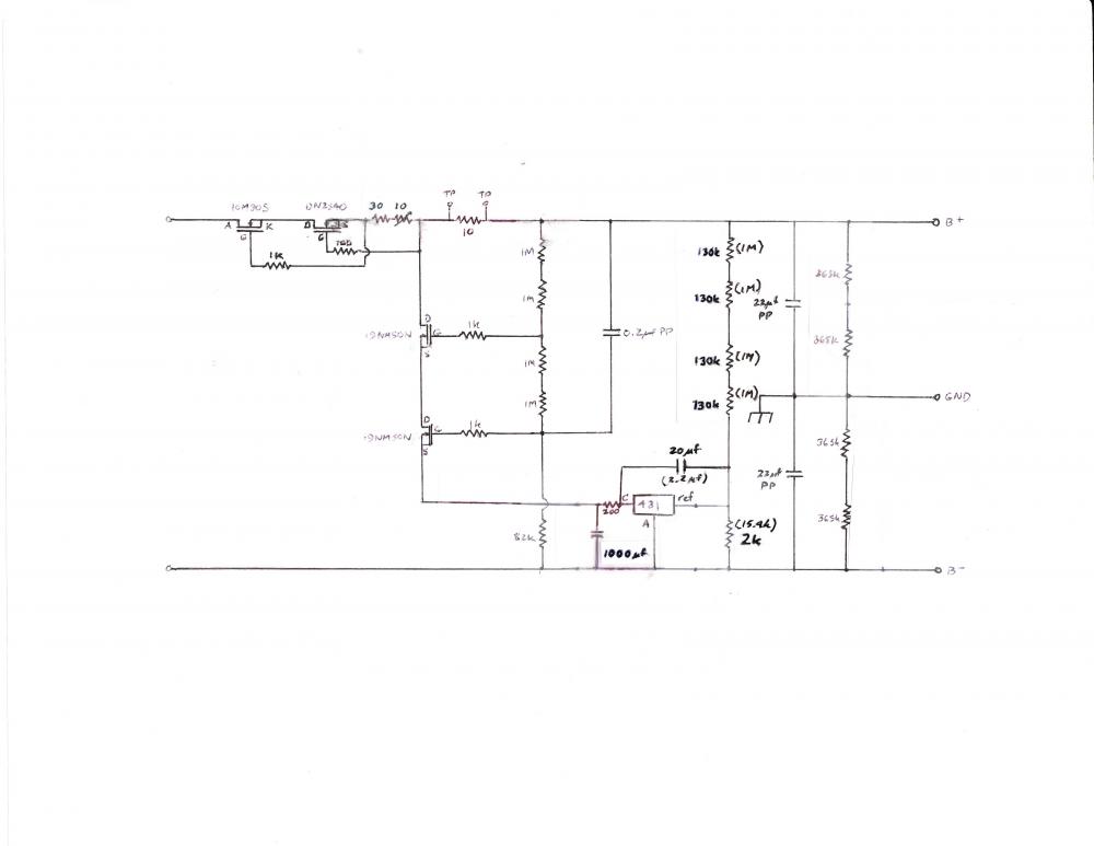
I've posted a revised power supply schematic and explanation on the SRX revised thread. This comes as a result of trying to make the supply quieter. Most of my attempts seemed to make it noisier, but after frying a few 431 chips, including getting some hundred plus volt oscillations, this is both quieter and more stable.
-
I have made a few revisions to improve the power supply – see schematic. First, the 15 volt zener at the bottom of the two MOSFET cascode shunt was deleted as unnecessary. Second, the 431 output filter capacitance was increased to 1000 μf to roll off its output noise above 0.8 Hz. Third, I now recommend running a 220 kilohm resistor from B- to each input tail current source, so I deleted the –C supply resistor chain. Fourth, I recommend floating both filament supplies rather than tying them to the high voltage supply, so I modified the voltage setting output resistors to all have the same value. Fifth I decreased the resistor chain values for the 431 chip the schematic shows the original values in parentheses. These are mostly deletions or changes in values but not in topology, i.e. if you leave out the component values the circuit looks pretty much the same as the original. Finally, I moved the capacitor from between reference and anode terminals of the 431 to across its cathode and reference terminals. Although this appears to be a very simple change, it significantly improved both stability and noise performance. The 431 has an internal op amp with a gain of about 55 dB and a bandwidth extending to between 5 kHz to 50 kHz before rolling off. This op amp is not unity gain stable, which means it can and will oscillate. Despite this, the 431 chip is widely used as a voltage regulator in switch mode power supplies in all sorts of consumer electronics, such as PCs, laptop chargers, cell phone chargers, solar panel charge controllers, etc., so various techniques have been developed to stabilize it. The regulator voltage is controlled by feeding back a portion of the output voltage into the reference terminal of the 431. Often a wide bandwidth is desirable to control both the DC voltage and cancel any AC variations across a broad spectrum. However, this design uses local feedback to the lower MOSFET via a capacitor to its gate to cancel any AC changes and noise, so we want to restrict the 431 to controlling the DC only. Broskie did this by rolling off the feedback signal using the capacitor between reference terminal and ground. But that did not affect the feedback loop gain, leaving lots of opportunities for oscillation. However, instead of limiting the feedback signal, if we limit the bandwidth of the 431 sufficiently, we both restrict its effect on AC voltage variations and stabilize it against oscillation. This is done by removing the capacitor between the 431 reference and anode terminals, and instead connecting it between the 431 cathode and reference terminals. In combination with the resistor chain between B+ and the reference terminal, this forms a negative feedback compensation loop that rolls off the gain of the op amp at 6 db/octave above its corner frequency. Since I modified the 431 resistor chain and output RC filter, I used trial and error to determine the needed feedback cap value. There were large oscillations with a 1 μf cap, while 3.3 μf produced smaller, slower oscillations but still managed to fry the 431. A 10 μf/50V polyester capacitor was stable with generally low noise, but random bursts of higher noise – however, the levels of the bursts were still below the 2 mV noise level in the original design. Increasing to 20 μf decreased the magnitude and frequency of the random noise bursts by about half. With the original 4 megohm resistor chain for the 431, a 2.2 μf cap should give the same gain compensation curve, so the simplest modification is to remove it from its original position across the reference and anode terminals and connect it between reference and cathode terminals. On the PS PCB there isn’t room to mount a 2.2 μf cap next to the regulator chip but you can drill a couple holes next to the 200 ohm resistor on the opposite side from the 22 μf output cap and run insulated wires to the two outer leads of the 431 chip. Note that if you are using a polarized cap, the + terminal should be connected to the cathode and the - terminal to the reference. This is the opposite from the previous connection where the + terminal of the cap was connected to the reference terminal. Replacing the TL431 with the quieter SPX431 dropped the noise voltage another 10 dB or so. With these changes, the broad-band power supply noise with a Fluke 189 DMM was decreased to around 0.16 mV into a resistor dummy load on the kitchen counter, with occasional bursts up 0.4-0.5 mV, so call it a -120 dB power supply. Not too shabby considering its simplicity. DC voltage overshoots by a volt or so but then remains within 0.1 volts of its target voltage due to the excellent temperature compensation in the 431 chip.
-
Don't have to wait. See my post from last Monday for some published internal pics of the Golden Gate taken from the 6 Moons review website and from Lampizator's own website. I especially love the way they bypassed the big capacitor with a smaller capacitor - is that electrical tape they are using, or duct tape? Inquiring minds want to know.
-
So, they now have almost everything on circuit boards rather than hard-wired. Here are some pics from a 6 Moons review and their website of their Golden Gate DAC, a mere 13,000 Euros - note how well the caps fit the PCB. Or not.
-
Ah, missed the resistor connection between the two halves.
-
Double WOW! Per OSHA, recommended time of exposure to 110 db dBA is 30 minutes.
-
I must admit I really admire your patience, perspicacity and erudition in crafting such a sagacious response to a relatively brief comment. You must have a lot of time on your hands.