JimL
High Rollers
-
Joined
-
Last visited
Everything posted by JimL
-
So, the amp consumes around 60-65 watts, similar to a KGSS. A 100 VA transformer should probably be adequate, although higher won't hurt, with the output voltage running around +/-375 volts raw voltage to have some margin during the summer when the AC voltage may drop 10%.
-
Oh my Gawd! That is fucking hilarious! I love it near the beginning where he says the holes in the two pads are "identical"!?!?
-
I think what Arnaud meant to say is, Fumier is French for manure. By the way, I don't know French but I do know Google.
-
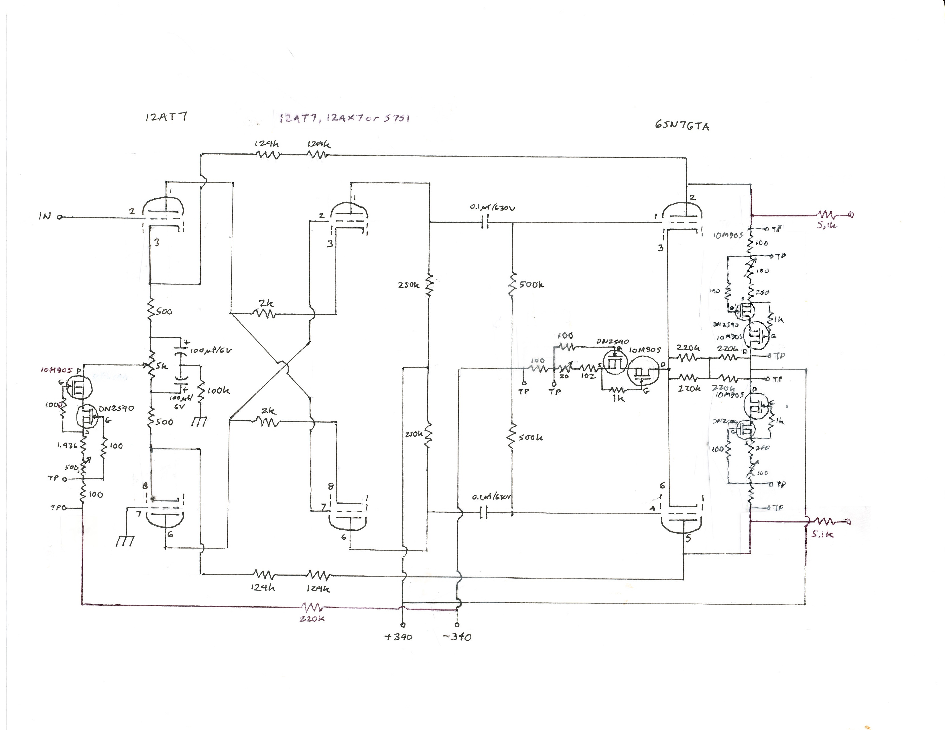
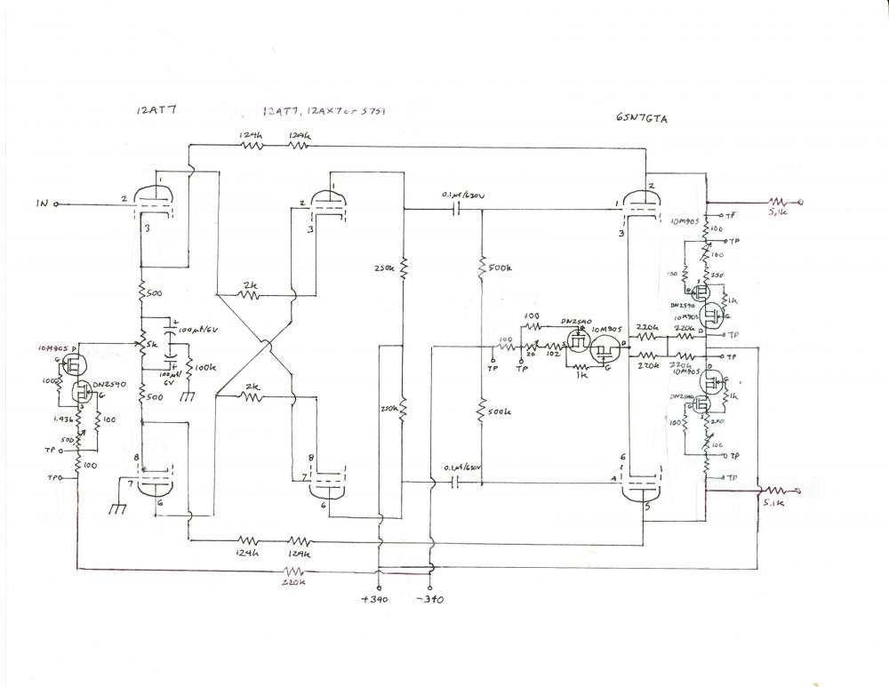
So, wanted to update this thread with the recent modifications to the schematic. Basically, this consists of running a resistor from B- to the input stage tail current source, and changing the top MOSFET in that current source from a DN2540 to a 10M90S, which increases its voltage limit. This should protect this current source from frying if one of the input tubes goes bad. With this change, C- in the power supply is no longer needed, so the only connections from the power supply are B+. B- and ground.

-
Beautiful build, Kerry! After building something so complex, you should relax...by building something simple.
-
I loved the Granada TV Holmes with Jeremy Brett, which are probably the most faithful to the original stories, but I also love Cumberbatch's Sherlock series. And I should like to point out that Brett was significantly older than the Holmes of the stories. In Study in Scarlet, the very first Sherlock Holmes story, Watson is just out of medical training, goes in the army and is wounded shortly after arriving in Afghanistan, comes back to England, which would put him in his twenties. He also comments after meeting Holmes that Holmes was not a medical student, which means that Watson thought Holmes was his age or younger. Brett was 51 when he started portraying Holmes, Cumberbatch and Freeman (Watson) are in their 30s, and Basil Rathbone, who also did a fine Holmes, was 47 when he starred in his first Holmes movie.
-
A couple weeks ago one of the 12AT7s in my SRX Plus failed, and in troubleshooting it eventually took out both input sections. On analyzing the failure it appears that I may have been just a bit too much of a cheapskate. Therefore I have slightly revised the circuit so that at least a failure won’t take out both channels, and hopefully won’t even take out one. The revision is pretty straightforward. Rather than supplying both input current source tails with a single resistor from B-, I substituted a 220k/500V rated resistor (270k/500V if you are using the original 300k plate resistors) from the B- rail to the input tail current source of each channel (which was previously marked on the schematic as being connected to -20v). The revised schematic is shown (ignore the +/-340 volt numbers, they should be +/-325 v). This resistor takes the place of the 10k and100k resistor chain in the shunt power supply that ran from B- to -C. This means that C- in my original power supply is no longer connected to anything, and the only connections between the high voltage power supply and amp boards are B+, B- and ground. For those using my shunt regulated current supply, you have to make a couple changes on the amp board. First, you have to cut the connection between the -20 volt terminal and one of the 100 ohm sense resistors, and then you have to cut the connection between that 100 ohm resistor and the other 100 ohm sense resistor. Then you have to connect each of those two sense resistors to a 220k resistor, which then runs to the B- rail – probably the closest place to do this on the amp board is the connecting point for the 100 ohm sense resistors on the output tail current sources – a bit of a kludge but it will work. In addition, I substituted a 10M90S in place of the upper DN2540 on the input current source. This modestly improves its performance, but more importantly should prevent the input current source from failing due to overvoltage. This modification does not need to be done for those of you who built the SRX Plus circuit using a Gilmore regulated PS, as that supplies the -15 volts that can be used for the input current sources.
-
-
Nope. I don't think Bob Katz did either. It's a little unclear to me if spritzer has the Mk I pads with Mk II springs on his Mk II or whether he has the stock pads and springs.
-
I used AC heaters in my SRX Plus and it is dead quiet.
-
To get back to the original topic, I've had an SR007 Mk I for a while, and recently I bought a new pair of Mk IIs for comparison, although I didn't listen to it until about a week and a half ago. I just listened for a couple minutes just to make sure it was working properly and then did the spritzer port mod. Prior to that, a couple of weekends ago I brought my SRX Plus and Mk I headphones to the first Albuquerque Head-Fi meet. I'm happy to say it impressed a number of people, including a couple of very experienced audiophiles. So much so, that one of them immediately went out and got a Stax Lambda Pro and T1 amp and sold his Sennheiser 800s. Last weekend I got together with a few of them, bringing my amp, Mk I and modded Mk II phones. The consensus of opinion was that the Mk I was a bit on the soft side - as one listener put it, "It's what I'd choose if I wanted to sit back with a glass of wine to listen for pleasure" - and the Mk II was more tonally neutral. So, using completely different amp and source, I would say that we came to the same conclusions as spritzer, Bob Katz and Tyll.
-
Well, maybe I'm confused, but the regulator is regulating the voltage between the B+ and B- rails but is not directly regulating either B+ or B-, other than the fact that the resistor chain across the output caps is dividing the voltage between B+and B- with respect to ground. So, the total voltage between B+ and B- are regulated but they "float" around ground with the average value set by the dividing resistor string. This is as opposed to KGs designs (as well as many others) where both B+ and B- are "hard" regulated with respect to ground. This is a disadvantage of this design topology. Does that make any sense?
-
Jose, aka Strawhat, noticed another error on the shunt power supply board. There is a missing connection between the input ground terminal and the output terminal ground terminal. The easiest way to fix this is to run a wire from the center tap of the HV transformer to both the input ground terminal and the output ground terminal. Thanks to Jose for catching this.
-
So, the one thing I would do differently is to set the current sinks and loads to close to their desired value before plugging everything in. The nice thing about the current sources and loads is that, due to their very high impedance, you can get close to the final values without using high voltage. You can do the preliminary adjustment as soon as the amp board is built without hooking up the high voltage OR filament voltage supplies. What you need is a voltage source of around 15-25 volts, so for example, 2 nine volt batteries in series connected with clipped wires will do. You connect the positive lead to the "upper" end of the current source and the negative end to "lower" end. Specifically, for the output current loads: Connect the positive end to the B+ terminal, connect the negative end to the junction between the 5.1 k output resistor and the 100 ohm test resistor Measure the voltage across the test resistor and adjust the trim pot to get 0.70 volts For the output current sink: Connect the positive lead to the junction between the 220k resistor string and the 10M90s MOSFET Connect the negative lead to the junction between the 500k grid resistors and the 100 ohm test resistor. Measure the voltage across the test resistor and adjust the trim pot to get 1.70 volts. Fot the input current sink: Connect the positive lead to the junction between the 5k trim pot and the "top" DN2540. Connect the negative lead to the -20v terminal Measure the voltage across the test resistor and adjust the trim pot to get 0.11 volts (if you are using 300k plate resistors for the 12AT7) or 0.13 volts (if you are using 300k plate resistors for the 12AT7). This will get you close to the final values. If you can't get to these values then you will need to adjust the value of the fixed resistor which is used with the trimpot to adjust the current. If the measured voltage across the test resistor is too high, you will need to increase the value of the fixed resistor, and if the measured voltage is too low, you will need to decrease the value of the fixed resistor, to shift the current range so that the trim pot can be used to achieve the desired current.
-
On this side of the Atlantic the Dynaco PAT-4 used a similar topology IIRC.
-
to quote Oscar Wilde: "I have the simplest taste. I am always satisfied with the best!"
-
Easy for you bakers to say. You're used to being around hot ovens!
-
Hopefully not with the unit turned on - peeing on a high voltage amp could be....interesting.
-
Part of it is what conditions you are running. If you look at the specifications sheets, you will see that an RN60 resistor has a power rating of 1/8 watt at 125 degrees centigrade, and a power rating of 1/4 watt at 70 degrees centigrade. So the power spec is "derated" at higher temps, which is not unusual. Which is where the confusion comes in - which is correct? If you're running the inside of your equipment at above boiling temps and need military grade reliability, then 1/8 watt rating for an RN60 is the way to go. If you're running stereo equipment inside your house, 1/2 watt rating is perfectly fine. At least, that's the way I read it.
-
Nope, the thread is generally it. Ask a specific question and you'll get a specific answer, otherwise the general philosophy of DIY on Head-Case is similar to Gobber the Belch in How to Train Your Dragon IME: Snoutlout: Wait, aren't you going to teach us first? Gobber: I believe in learning on the job. [releases the dragon]
-
Honestly, it doesn't matter to me what you build, that's what DIY is about.
-
Well, I missed that on the PS board also.
-
Also remember with a shunt regulator that you MUST have the high voltage MOSFETs attached to the heatsink before testing it or it WILL BLOW UP! I used four 20k 20 watt resistors in series parallel to make a 20k 80w dummy load when testing out the high voltage section of my regulator.
-
The SPX431 is Exar's improved version of the TL431 adjustable IC shunt regulator. It has about 10 dB less noise than the basic version and is available at Mouser. The TL431 is the control element that sets the voltage of the regulator. TIL731 is something completely different and will not work in this circuit.
-
Ah, OK, got it. I agree with you. Engineering decisions are rarely good vs evil, which is why I usually try to present advantages and drawbacks in a discussion.