


JimL
High Rollers
-
Joined
-
Last visited
Everything posted by JimL
-
Fixed it for them.
-
Not a member of the Stax mafia, but...it's a glorified SRD-7 in a fancy case.
-
I agree with Jose. The output voltage can jump around when the amp first starts up, BUT, the output voltages track - in other words, if the R+ output is +50 volts, the R- output is also close to 50 volts, and the same with the L+ and L- outputs.. This is because the output stage is differential. Since it is the difference in voltage that produces sound, ss a result, the headphones see very little difference between the two stator plates, so there is no appreciable turn-on thump.
-
Yes, I think they are doing a baseline EQ for 8 dB down, then varying the compensation with volume to match the Fletcher-Munson, Robinson-Dadson or some other equal loudness curves, plus adding in some expansion, but the variation occurring separately in three frequency bands, possibly depending on the loudness within each band. At least, that's what they seem to be saying - or I could be completely off base. Hard to know from the vague description, and I have no idea what sort of psychoacoustic research they have to back it up, if any.
-
Could be a couple of things going on. First of all, what are your input stage plate resistors? That plus the input tail current source sets the plate voltages. If your B+ is around +370 volts, and you have 250k plate resistors, you need the tail current source to be running at 2 x 185/250k = 1.48 mA. If you are running 300k plate resistors, then the tail current source should be 2 x 185/300k = 1.23 mA. If B+ is at +340 volts, you want the upper plate voltage to be at 170 volts, which means the tail current source should be 2 x 170/250k = 1.36 mA for 250k resistors, and so on. Once you have set the tail current source to the proper value, you should have the plate voltages close to the desired value. If you are not able to balance the tubes, you need to either swap tubes around until you can achieve balance, or replace the tubes. Not sure about the source of the hum, but if the tubes are bad that is a possibility so I would try replacing them. Otherwise, there could be a ground loop, and those can be a b***h to track down. You should begin by checking your grounds - the amp board should go to a star ground, as should the PS board. Sometimes hum can come from the power cord ground, in which case lifting it from ground with a 10-100 ohm resistor can help. I seem to recall someone posting a diagram for the KGSSHV showing how to connect all the grounds, inputs and outputs, but I can't find it at the moment. I am working on an update to the shunt regulator so I wouldn't recommend building it at this point. The KGBH PS board is well sorted out and works fine.
-
I got a notice that it is up on Massdrop. The Massdrop pictures seem to show it with a wall wart type supply. I've already got a Mk I so I didn't pay a lot of attention to it.
-
If you're serious and not tongue-in-cheek, the specs on the RKV Mk III through the "impedance" (transformer) give just over 1 watt into 8 ohms. It's not specified for 4 ohms, but that is a tougher load. You should be able to figure it out from there.
-
Speaking of old circuit boards, I remember doing mods on Dynaco phenolic PAS-3 boards.
-
Well, you can do the same mods on the newer SRM-006, and similar mods on an SRM-007 using 7.5 mA constant current loads.
-
Actually, he says the transformers are from the Stax F81X electrostatic loudspeakers. As to why a transformer designed to sit between a power amp with a couple ohms or less impedance and a large capacitative load (the F81) would be a good choice for a 6336A tube output with a couple hundred ohms plate impedance driving a small capacitative load of around 100 pf...?.
-
Don't know about the pictures. Copied directly from p12 of the HF thread "Stat SR009 and T2 successors confirmed for spring 2017"
-
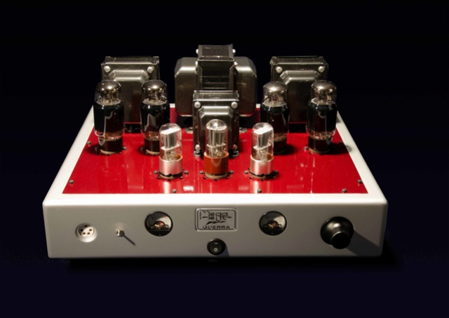
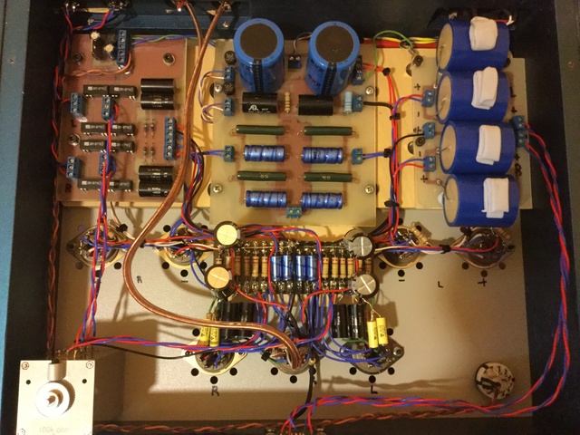
You missed the best one, the Guerra (Italian for "war"), which has...wait for it....output inductors. Oh, wait, sorry, here's what the manufacturer says, "Although it may seem like our truncated circuit, it has been designed with great care and the output inductance has been realized as a high level transformer, on two holes, with different splits, just like a secondary output transformer!" Outside: Inside: Looks like passive power supply.
-
Just up on InnerFidelity - Katz's Corner has a review of the KGSS Carbon and Dynalo Mk II built by Mjolnir Audio - well done, kevin and spritzer! He used an SR-007 Mk II with port mod and LCD-4 for the reviews.
-
-
Of course, Trilogy is not clever enough to use MOSFET current sources.
-
Yes, there are still NOS 6SN7GTA/B tubes at reasonable prices, and reportedly the new manufacture TungSol 6SN7GTB tubes sound good, according to both Upscale Audio and Jim McShane.
-
Electrically, there probably isn't enough of a difference to be meaningful in terms of drive capability. Sonically, there are lots of versions of the 6SN7GTA/B available, both NOS and new, moreso than the 6N6P, which gives the end user an opportunity to modify the "flavor" of the amp. That could be considered an advantage or a disadvantage depending on your philosophy.
-
Well, it does appear that Schiit, Kingsound and Trilogy have all taken their designs from Stax circuits developed in the 1970s, without paying attention to anything done since. A pity, really.
-
I'm not an expert in the different T1 versions, spritzer is much more knowledgeable on that. AFAIK, the T1W used a later version of the board (the early version has the PS caps running across the board from right to left, looking from the front of the amp, whereas the later version has the PS caps on the right side of the board going from front to back). It's a bit easier to modify the T1 and T1S versions as the heatsink for the constant current sources can be mounted on the side of the case, over the part of the circuit board that contained the output resistors, as shown in the photo I posted. However, in the T1W you'll have to figure out a way to mount the heatsink close to the location of the output resistors, as that part of the circuit board is not adjacent to the side of the case. Unfortunately, I am not aware of anyone in the business of doing mods on Stax amps, or people who build amps for others, other than spritzer, who does KG builds but not mods, as far as I know.
-
If spritzer is correct that the output tubes are 6N6P, the data sheet says their maximum plate dissipation is 8 watts total for both anodes, max static plate voltage is 450 volts. Pretty similar to 6SN7GTA/B at 7.5 watts total and max static plate voltage of 450 volts. I note that the most recent ECC99 data sheet lists plate dissipation per side as 3.5 watts (down from 5 watts in the original data sheets) and max static plate voltage of 400 volts.
-
Just what the world needs. A variation of a 40 year old design, with passive power supply - for 5000 pounds??!!!?!?
-
Whatever, personally I think they're just variations on a theme. But, run your simulations with the SRX circuit, the Birt circuit, and the SRX circuit without the cross-coupling, but with fixed bias on the upper tube grid, and see what you get.
-
So, what is the circuit board at the bottom of the box? Regulated PS?
-
The first place I saw this circuit was in an electrostatic amp design by Joe Curcio using 6DJ8 tubes, which was published in the very first issue of Glass Audio (Vol 1, no. 0), 1988. That's where I found the reference to the Birt article. I had to go to the MIT library to find a copy of the article on microfilm. I have it in a pdf file so if you PM me, I can send you a copy. Here is a quote from the article (part II): "From a discussion of the general principles in last month's article, the requirements for the first stage of a practical amplifier are now fairly clear. We have seen that for good balance and low push-push [as opposed to push-pull] gain, [tubes] V1 and V2 should have a high gm and large anode impedance...... A better plan is to substitute cascode stages for V1 and V2. It is generally possible to achieve a higher gain in this way, and a screen grid supply is not required. The grids of the upper triodes of the cascode pair require ideally to be at a constant potential relative to cathode. This is not a difficult problem, as we may decouple the grids to cathode, and make the grid feed resistor large. Alternatively, a cross coupling arrangement can be used as shown in figure 9 [this is the cross coupling the SRX uses]. The operation of this circuit is relatively interesting. When a push-pull signal is applied, it can be seen that the drive to the upper triodes of the cascode pair is applied to both the grid and cathode, in anti phase. As far as the cathode circuit is concerned, this turns out to be equivalent to doubling the gm of the upper valve, and therefore the cathode impedance is halved and the voltage gain to this point is halved. However, the grid-to-cathode voltage of each upper triode is the same as it would be in a conventional cascode amplifier, and the overall gain is similar." My comments and clarifications are in [ ]. The article then goes on to plot the V-I characteristics of the cross-coupled circuit using 12AX7 tubes, which, surprise, look just like a standard cascode, i.e. pentode-like. You may not like to call this a cascode because it doesn't keep the grid of the upper tube constant, but considering that cascode was originally coined as a contraction of CASCaded triODE, that the connections of the two tubes are the same as a standard cascode (plate of lower tube to cathode of upper tube), the same current runs through both tubes, and that the V-I curves of this circuit are the same as a standard cascode circuit, I don't know what else you could call it. Just don't let those two extra lines confuse you. Note that the SRX input circuit is NOT an LTP into a common cathode because of the connection between the PLATE of the lower triode to the CATHODE of the upper triode ON THE SAME SIDE. The common-cathode-like connection of the PLATE of the lower triode to the GRID of the upper triode is on THE OPPOSITE SIDE. This is the cross-connection. Take it out, substitute a fixed voltage to the grid of the upper triodes and you have the Hedge circuit, which is a cascode differential pair (balanced) or cascode LTP (single ended). Given that the gain of the cross-coupled circuit is the same as the standard cascode, I calculated the gain as about 41-42 dB, and an output impedance per side of close to 147 kilohm, using the estimated rp and gain for the low current used in the SRX circuit. That's with my 250 kilohm plate resistors rather than the original 300k. If you use the standard published 12AT7 parameters, you'll get a slightly different answer. The input capacitance of the input circuit is low because of the cascode connection. The issue is the high output impedance of the input stage into the output tube Miller capacitance. With the 6SN7GTA/B, the Miller capacitance is about 84 pf, and the circuit rolls off above 11-12 kHz. There is about 14 dB feedback at low frequencies, and so the calculated closed loop gain rolls off above about 53 kHz, which is what I measured. "
-
First, ignore the cross-coupling for a minute. If you fix the voltage of the grid of the upper tubes, you'll see that you have a cascode circuit with a common cathode for the lower tubes and a "grounded grid" for the upper tubes. Now, with the cross-coupling, what you have is the plate signal from the left lower tube going to both the cathode of left upper tube and the grid of the right upper tube, and vice-versa. Remember that plate signals from the two lower tubes are out of phase. So what the upper tubes see is double the voltage signal between the cathode and grid that they would without the cross-coupling. It's still operating as a cascode, just that the voltage signal to the upper tube effectively doubles because the grid and cathode signals are out of phase. If we analyze the upper tube in isolation, it looks like it has double the gm (change in current out for change in voltage in) because the same grid signal now results in twice the variation in current due to there also being an anti phase cathode signal. This results in twice the voltage gain for the upper tube. However, for the lower tube, as it is feeding both upper tubes its current signal is split for the same voltage input, so its gm is halved. The result is that the overall gain is about the same as a cascode without the cross-coupling. So if there is no change in the voltage gain, what is the point of the cross-coupling? Well, if there is a difference between the output signals of the lower tubes due to a single ended input, then the cross-coupling tends to balance it out because the output of the lower tubes feeds both the upper tubes.


