


Tinkerer
Returning Member
-
Joined
-
Last visited
Everything posted by Tinkerer
-
Yeah, I was about to edit my post. I had a 50V laying around that I temporarily added in series. That jumped it up to 635. So I figured it just needed a little less. I tried swapping in a 150V in the 130 slot and it jumped up to about 610. So I just put it back to stock and it went back to 530. But I noticed the very last time I measured it, that it would start around 570 and then drop down to 530. It might be fine. All the changes add up about right. It's just the particular combination I need that's giving me funny numbers.
-
Got the new zeners in, and installed them. Still only getting 536V now at the bias test point, and that's basically tolerance difference. I'm guessing that means I need to replace either the IXYS 10m90s or the 3k resistor in front of the zener string. I don't really see what else it could be.
-
Yeah. I put in an order for enough to redo it twice if I need to. They should be here in a couple of days. On the good news end though, since the amp driving parts are fine, I hooked up each amp board individually to test them after installing all the new parts. Everything fired up. Got the balance and offset set on the first one then let it warm up before I tweaked it again. Then I disconnected that one to test the second one and so I could install the servo jumper on the first board. Second one is still warming up but it's doing fine.
-
I just checked and they actually all measure within tolerance. 130, 144, 148, 146 Should be 568V total before warm up. But reading from the test point I'm getting 527V. I'm probably doing something stupid with the measurement, but I'm getting the same reading in front of the ballast resistor as the test point. I'll look at the schematic closer tomorrow with a fresh pair of eyes and see if I can't figure out where my screwup is.
-
The values of the parts are correct, 3 150V's and a 130V. I guess one or more of them is damaged. I'll pull them and get them measured, see what else I need to buy.
-
Mouser order came in today. Just tested the power supply after installing the new parts and jumper, and double checking everything. Nothing exploded. +/- 494 on the 500V rails and +/- 14V on the 15V. Feels good, and wouldn't be possible without all the help I've gotten here. Bias at the test point only reads about 520V though.
-
They're the exact same as the schematic, just as you listed. But I think they were slightly newer production as the O, GR, and Y identification were on the side label instead of the top like the originals on the IS amp board.
-
Just thought I'd chime in that I got my NOS 2SC1167's in today and replaced the stopgap C3148's. Sounds good. Voltage drifts more than it used to though, but still less than a volt. Haven't listened enough to tell how different it is. Now the only original parts left on the output boards are the small fets. I think the old girl is about as good as she's gonna get at this point. Now off to work on the KGSSHV and try not to blow it up.
-
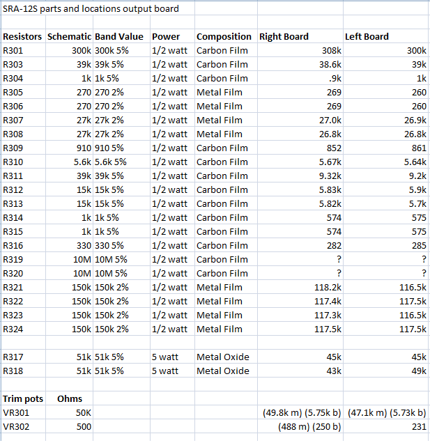
The 50k is the balance pot for each card. The 500 pot is to adjust the voltage. I got distortion kind of like that when the right channel card was unbalanced. I also measured balance and voltage from the top of the power resistors and not the transistors, but I don't know if that makes a difference. Why are you turning on the extra 20db amp board though? Isn't that supposed to add lots of extra noise? I know it raises the noise floor on mine. Dead quiet without music at any volume level without it, faint static at high levels with it on.
-
Right. Thanks. Reading through again, I understand a lot of the 'I' bits are for if ixys parts are used in other positions besides the current source. Also took a look closer at the psu schematic, saw where the voltage multiplier section was and what traces the jumper should connect. Following it through I discovered the actual real jumper slot I had overlooked. Boy do I feel like a dumbass. Otherwise, found out the zener strings are correct at 550v, desoldered the stuff that needs to be replaced, put in my mouser order, tapped the holes for the amp feet+ sanded one of the rear ones to use for the chassis ground, and enlarged the attenuator hole to fit. Just waiting on parts to do more now. EDIT: And confirmed global feedback is the default in the back pages of the thread. I remember reading somewhere a long while back that there was originally just one option, then the second was added and then nobody used it so it was removed again. So that was the case, and it was global in the beginning. Good thing to dig up as the jumpers for that are currently set to local. Still only about halfway through the thread, but I'm getting there. Hopefully I'll be all caught up by the time parts start arriving in force on Monday. It's just a pretty good read anyway, with some great tips on parts and suppliers and how to break ground loops and such that have been very helpful. I really appreciate you all helping out with my stupid questions as well. EDIT 2: Just to be clear, I don't hook up the servo until I'm sure everything else is fine on the amp boards and make the initial balance and offset, correct?
-
Thanks for all the help so far. I'm up to about page forty of reading the whole thread, about the point when the original battery stuff was getting replaced with the zener string in the layout. Main helpful bit that I picked up there so far is the exact part number needed for the nylon washers and the exact screw sizes if I need any more. Looking up the A1156 sheet and comparing it to the BOM unit, they are only rated to 400V instead of the 600V of the 2SA1486. The extra gain seems nice but I don't know how they'll hold up. I know it's a pain to answer some of these questions. I just really want to only have to make one mouser order for everything, barring doing something stupid and blowing something in the PSU or other such pitfall. Right now the list for parts is: For PSU Correct isolating diodes for the HV rectifier bridges Zener string replacements to guarantee right value (Before that, I'll get them desoldered and identify them. They might be the right values after all.) Faraday 7815 and 7915 that need to be populated. For Amp boards Nylon washers for the IXYS parts with isolators 174k resistors that need to be populated (thanks for the alternate part there) Ceramic caps that need to be populated 5.1k resistors to replace the 7.1K 180 resistors to replace the 250 1k resistors for the "1K I" labeled bits even though I don't know if it's needed Some LED's But an additional question I had was, could a normal 4 pole 12 pin switch be used to bypass the volume pot the same way you can on an SRM-727? I have a preamp to control the volume to the amp directly and would like to have the option to do that. Best pot is no pot right? I know speaker switches are common as dirt but I don't know how that sort of thing affects SQ at this level, if it does at all.
-
-
Great. That squares with the schematic only showing the alternate current source in the lower left as different parts. So the only questions on the amp boards left is do I put in the '1K I' labeled resistor spots in the upper right and what do I set the G/L jumper to in the center of the board. Oh, almost forgot, what's the size for the nylon screws/washers that will fit the heatsinks? Other than that, went through the psu and listed the discrepancies where they seemed like they might be important. So stuff like a couple of the smaller caps having more than minimum capacitance values I left out. Also not quite sure if the zener strings are correct as the schematic reads 150/150(200)/200 and the PCB reads 150/150(200)/150. Might just replace them all to be positive. Seems like the 680uF 450V caps are bit of a pain to come by too as there's a group buy going on and the one in the BOM is OOP.
-
Soldering actually looks good on the bottom. It's just none of the flux has been cleaned off so the board bottoms are ugly as hell at the moment. I'll get it all prettied up and probably reflow everything just to be safe. At the least though, for what cost me about $700+ shipping (trade was worth a lot more but that's what I paid for what I traded), I don't mind spending a little time to fiddle with things. Edit: Looking over the BOM for the amp boards here again https://docs.google.com/spreadsheets/d/1tQvwqsARXGge6Tw6edqicCDti6Mite2F24T5YddyEEc/edit?pli=1#gid=0 It has the 250 ohm R for the IXYS parts build. But I can use 180 ohm R in an IXYS current source 500v build as long as the onboard sinks dissipate the heat? Otherwise, it seems most of the parts I thought were missing have the A designation so should be left alone right? The mentioned jumper in the upper right is also marked A instead of I. So it should also be left alone? I also needed to ask again about the local vs. global feedback jumper. What's the standard everyone uses in their builds?
-
It affects the amp boards as well. Or maybe it just does on mine since mine is missing the phono board. Anyway, mostly just posting the transformer current read 250ma and 50ma on the secondaries. Figured it would be a good time to take the readings as my mouser order just came in for a full output board rebuild minus the fets and my soldering iron was warmed up anyway. EDIT: Installed full resistor replacements, all Xicon and big ass Dale RN60D's. As everyone probably figured, the static was after all a bad resistor. Still have the original TO-3 replacement transistors coming in too thanks to some help from you guys, but it sounds great right now with the SR-007. I actually like it better than my old feedback-modded 727A. We'll see if the original configuration changes that.
-
Just finished going through the amp boards part by part and other than a couple of 7.1k resistors in place of 5.1k that need to be replaced, I had two things that needed checking out. First is that there is a slot for an extra pair of 1k resistors that aren't in the current revision. Second is that there are a pair of 250 ohm resistors installed and the PCB matches that value, when the latest revision is 180 ohm. So would it be better to follow the original board or to put jumpers over the 1k and swap the 250 for 180 to bring it up to current? Will go over the PSU next.
-
I traded for it, but yeah.
-
Two of the devices on each amp board are IXYS. The rest are the 4686. The PCB below seems to match that but I don't know if that's correct or not. If I'm reading the website stuff right, and I very well might not be, the amp boards still need to be fully populated as well no matter what which means I still need 4x 175k 1/2 watt resistors, 2x 1k 1/2 watt resistors, 2x 1.2k 1/2 watt resistors (board says 500 but BOM says 1.2k if using the IXYS), 2x .47uF/50v caps (ceramic/mica), 2x 5pF caps (ceramic/mica), and two LED's per amp board. Comparing to the BOM here https://docs.google.com/spreadsheets/d/1tQvwqsARXGge6Tw6edqicCDti6Mite2F24T5YddyEEc/edit?pli=1#gid=0 that means I need. 8x 273-174K-RC Xicon resistors (nonstock mouser) I'm guessing you can't swap in the Dale CMF55174K00FHEB because it's only rated 250v instead of 350? 4x 273-1K-RC Xicon (in stock mouser) 4x 273-1.2K-RC Xicon (in stock mouser) 4x 810-FK16X7R1H474K TDK cap (in stock mouser) 4x 75-561R10TCCV47 Vishay cap (in stock mouser) 4x 859-LTL-307ELC LED's (in stock Mouser) Also found the jumpers for Local/Global feedback. They're currently set to local. I remember how terrible the no-feedback sounded on my 727A with my SR-007 and I think the mod that fixed it changed that to global. What would be recommended here? I think the global/local option later got removed entirely in later revisions of these boards right? So there should be a clear better option.
-
Yeah, definitely wanted to go over this thing with a fine tooth comb before putting any power through it. This was one of those projects that was 80% done that I picked up because I figured it would be easier than starting from scratch, especially with the case stuff almost all done already. I just need to tap holes for the case feet and enlarge the tap for the volume pot a hair. Also, looking closer at the transformer and comparing to the website specs, this is the 500v version after all, not the 450v. The amp boards look to have the correct IXTP01N100D for it installed as well. I think 500v means I need a jumper in place of one of the missing film caps? I'm still trying to puzzle out the rest. I'm getting a mouser order together for what I lack. So far I know I still need 8 STM STTH512FP to replace the Vishay ETF12's in the rectifier bridges.
-
I just got set of the onboard heatsink boards, mostly populated and the enclosure mostly already put together. I just needed to check if everything was set up for 450v and global feedback and if anything obvious is missing since I don't know what's different between versions. It's revision .61 so I think a bit older than current?
-
There's a pot you can use to adjust some stuff in the PS by the two big caps next to the transformer. As for the transformer, the primaries are like a mirror of the one on the SRM 1, right to left instead of left to right 120 100 G 120 100 G CG |___|___| |____|__|__| ________ _______ 230 CT 230 18-CT-18
-
230-0-230 and 18-0-18 IIRC. I think the original was supposed to be 260-0-260 and 26-0-26 looking at the boards? But it seems to be putting out what it needs to with the pot adjusted in the back. The pro bias measured 579v in front of the ballast resistor and the normal was adjusted to 230v. Don't have current readings unfortunately. Will try to get some when I get a new battery for my multimeter. Also just bit the bullet and grabbed a full set of higher rated resistors from mouser except for the power ones I already replaced. All dale and xicon so quality should be no issue.
-
Well, I wound up needing some more help. The reason I was even replacing anything on this was because after a couple months, I started hearing slight static in the right channel that would come and go. It had been working perfectly again the last time I posted, but it's started up again. Here are the symptoms. 1. Problem switches sides when I switch boards. 2. Leaving the meter to read balance after it has been zeroed when it happens, I get a 4-15 vdc difference when I hear the static. Then it goes back to 0 when the static goes away. 3. It's not a cold solder joint. I must have reflowed everything twice not counting replacement parts. 4. It's not the two main transistors. It still did the same thing when I tried some replacements. Any ideas? I'm hoping it's not the smaller transistors. EDIT: Swapped jfets in from the 30db extra gain board (2x K30A O and 2x K30A GR), which accounts for all but one on the output board. Didn't fix the problem. I also have some measurements for the resistors but they were taken on the board so not terribly accurate sometimes. When I replaced some, they usually would measure within tolerance when removed from the PCB.
-
Thanks. Everything's running great now. EDIT: Set output boards to the proper 290VDC and keeping them there. I'm mostly posting to show what mine looks like since it's one of those that's certainly had an interesting past. Something may really off that I'm not seeing. As far as I can tell, this is what was done to it at some point before I got ahold of it: New electrolytic caps New bando transformer with winding combinations for any mains voltage Pro bias breadboard epoxied to chassis and pro socket added Phono board removed for some reason Main transistors replaced and heatsinks added for them Then this is all I did: Rewired from 100v to US voltage Replaced caps on output boards Replaced 3/4 power transistors (the ones replaced were about 10% off and now they're all within 1%) Replaced pots with multiturn ones Reflowed everything on output boards
-
Thanks. That really helped out. I didn't realize whoever put in the new transformer before me was undervolting the boards at 320VDC. Had to adjust the pot in the back of the amp to get the voltage up on the output boards before I could get those numbers. EDIT: I just saw on the previous page that 290VDC had been recommended before. Don't know how I missed it when I must have read this thread five times over the last few months. My replacement power resistors are rated 10 watt and the replacement transformer is much beefier than the old one so whatever I throw at either of them shouldn't be a problem I think. Pretty sure everything on the output cards are rated 500V+ as well. Should everything still be fine at 390VDC? Just want to make sure I'm not missing anything.

