Shawn
-
Posts
105 -
Joined
-
Last visited
Content Type
Profiles
Forums
Events
Everything posted by Shawn
-
Hi, @MLA I'm planning to test this next month, and I have one more question: The low-voltage ±15V supply GND on the Carbon PCB is connected to the high-voltage GND. Does the ±15V supply also need to float somehow in this configuration, or should I simply connect the GRLV GND to the Carbon GND as normal? I'm trying to make sure I understand the grounding scheme correctly before I start wiring everything up.
-
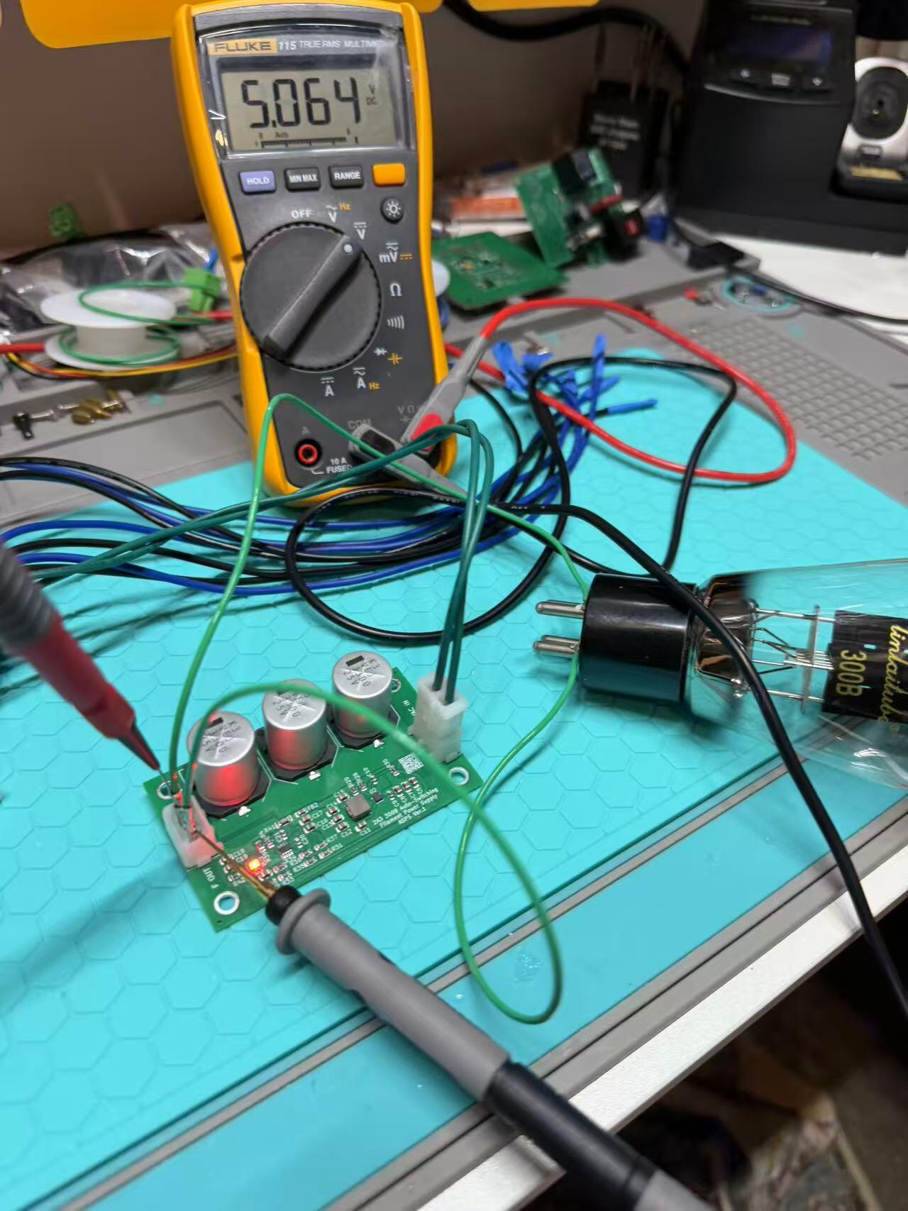
Did some testing today on the auto switch filament board. It seems to correctly detect 2A3 300B so far. For the test, I directly soldered the cable onto the 300B filament pins. I know that’s not the best practice, but it was quick.

-
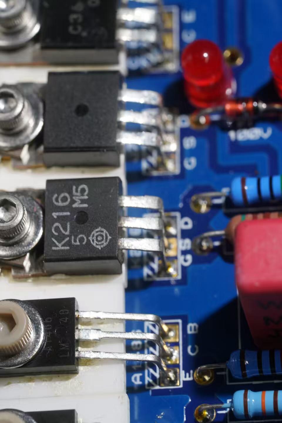
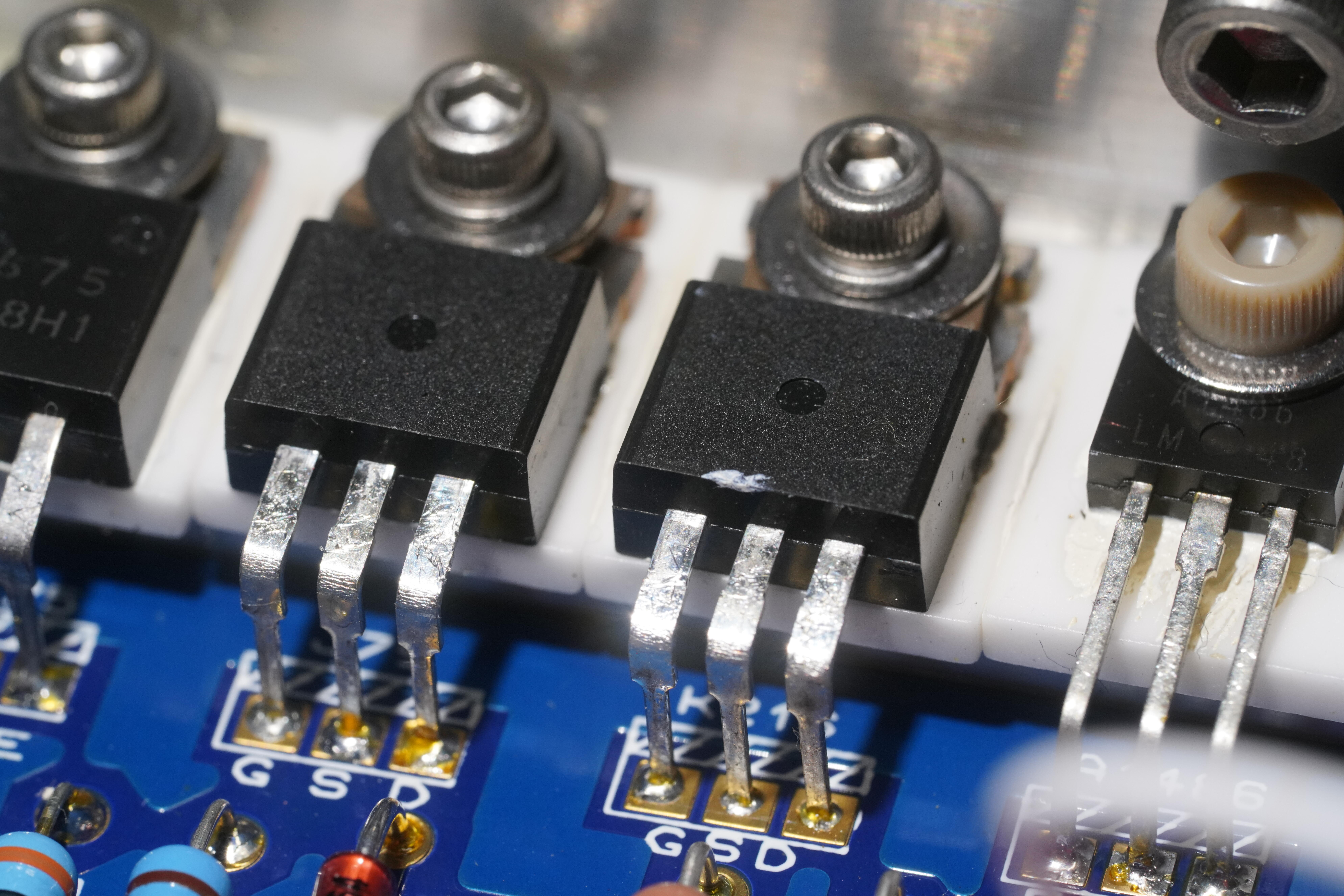
Thanks for your reply, Pars. The photo angle isn’t ideal. In real, at a certain angle under light, I can barely make out the 2SK216 / 2SJ79 markings, but they are extremely faint. I’ve seen genuine Hitachi versions before and they look quite different. I’m not sure if Renesas production ever looked like this, but I personally haven’t seen any sands with markings this faint. Below is a comparison. On one side is what I believe to be a normal 2SK216, and next to it is the suspicious 2SJ79. This T2 actually has a mix of both types of markings installed.
-
I’m currently helping repair a DIY T2, and while inspecting the amplifier section, I came across something a bit suspicious. The 2SJ79 / 2SK216 devices look like this (see attached photos). The marking on them appears very faint and somewhat unusual: not what I would normally expect from these parts. This makes me suspect that they might be counterfeit or at least not from a reliable source. Has anyone here seen this kind of marking before on genuine 2SJ79 / 2SK216? Any insight would be greatly appreciated.
-
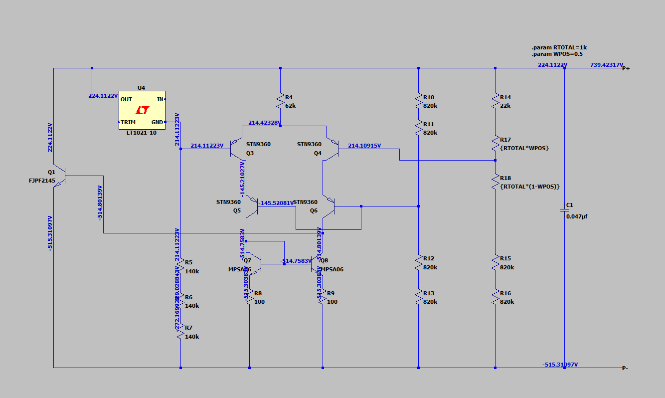
Thanks to @MLA for sending me a few FJPF2145s. To avoid turning them into smoke immediately, I’m currently still in the simulation phase. So far, the battery section appears to behave properly, at least in theory🙃 I’ll also try simulating a few alternative devices to see how they compare. From what I’m seeing so far, a Darlington configuration might actually make more sense in this position. More updates once I move from theory to reality.
-
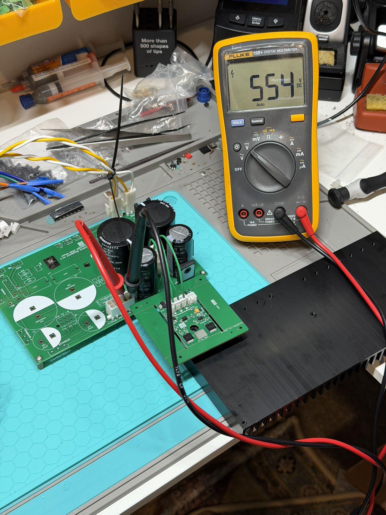
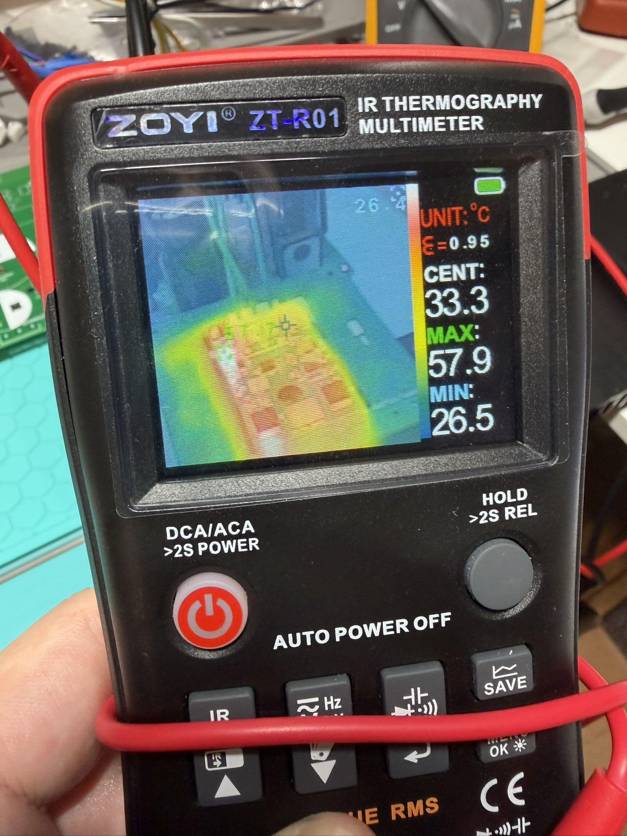
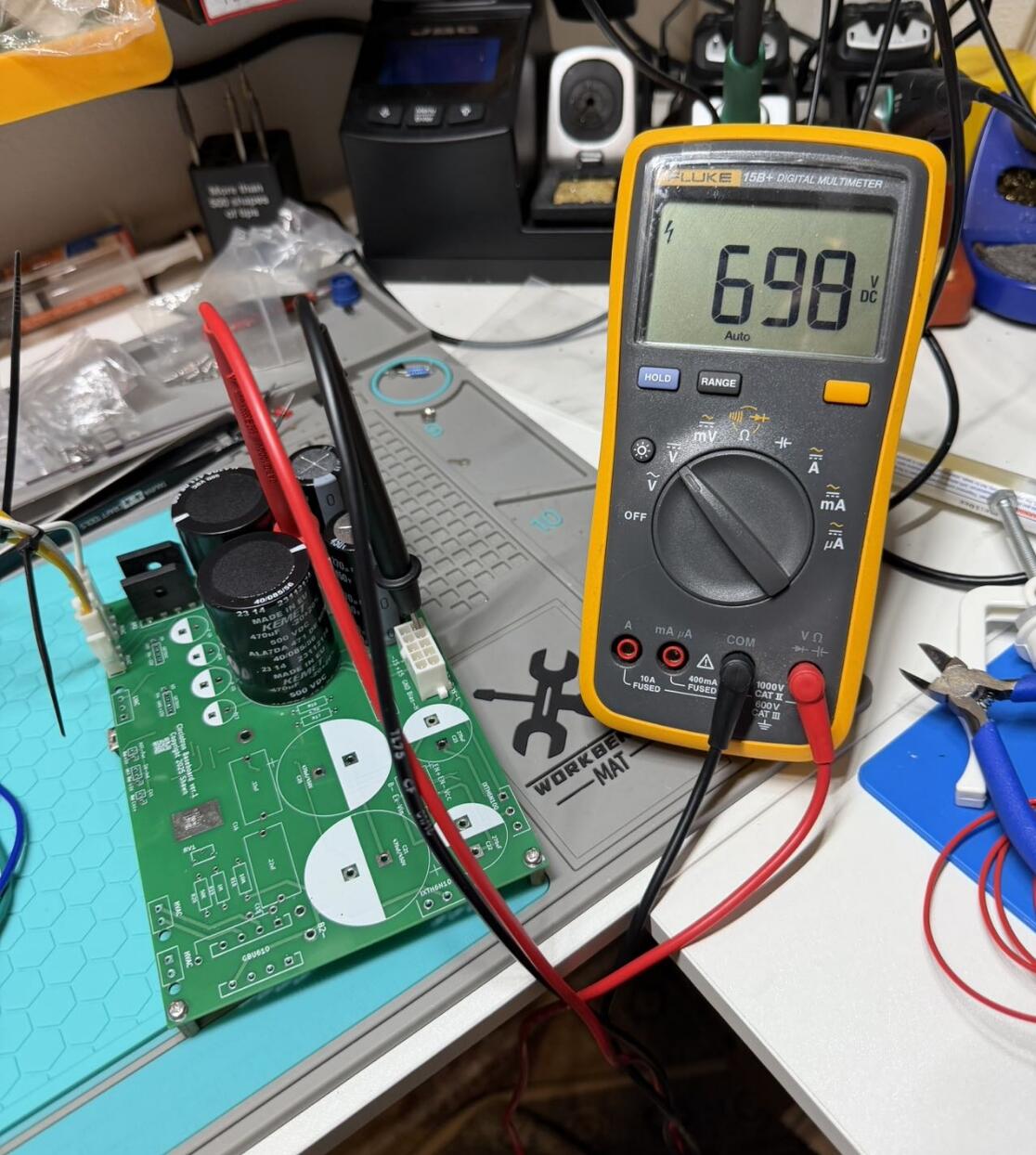
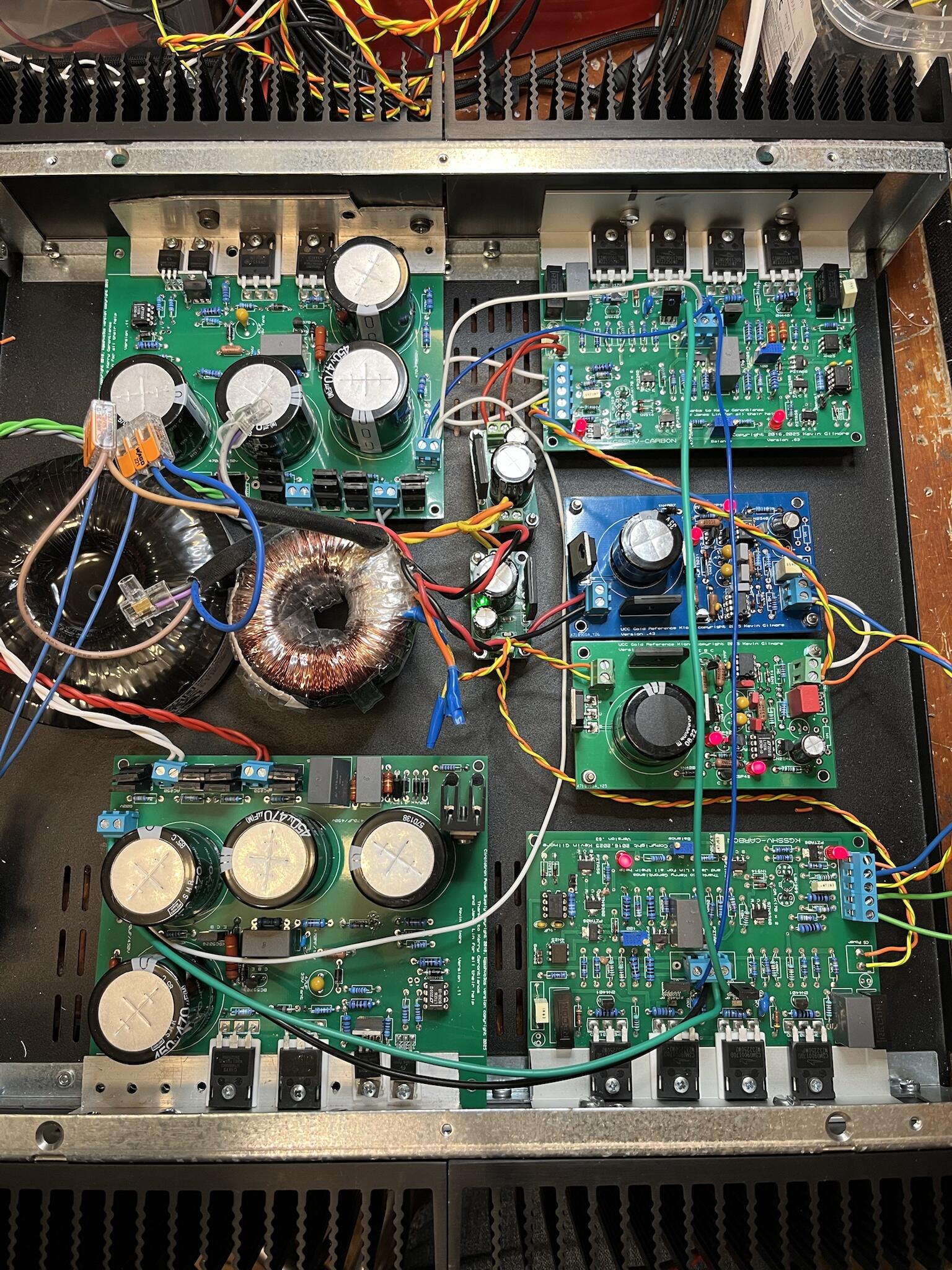
OK. Did a first power-up test for CRHV today. With 360k set for 550 V, I’m measuring about 554 V in practice. I only let it run for ~10 minutes. A quick IR check shows the CRHV peak temperature at ~58 °C. I suspect running it from dual 250 VAC inputs targeting ~600 V output may result in slightly better thermal behavior. At the moment, only the high-voltage section is populated. The delay soft-start and ±15 V sections are not installed yet, but they should function as expected once added.
-
It’s 2026 and FJPF2145 (and 2SC3675 in some builds) have been discontinued for quite a while. So far I’ve come up with a few candidates: KSC5026 BUL216 (I remember this being mentioned before) FJP5027 My main concern is output capacitance. I’ve seen comments that BUL216 has relatively high capacitance, and the other candidates seem in the same ballpark. Their Ic ratings are ~1.5A to 4A, and gain (hFE) looks acceptable. But I’m worried about any impact on stability. Has anyone actually tried one of those (or any other modern parts) as substitutes for FJPF2145 / 2SC3675? Datasheet attached: https://www.onsemi.com/pdf/datasheet/ksc5026m-d.pdf https://www.onsemi.com/pdf/datasheet/fjp5027-d.pdf https://www.st.com/content/ccc/resource/technical/document/datasheet/group1/01/eb/74/95/d4/55/44/6c/CD00000009/files/CD00000009.pdf/jcr:content/translations/en.CD00000009.pdf
-
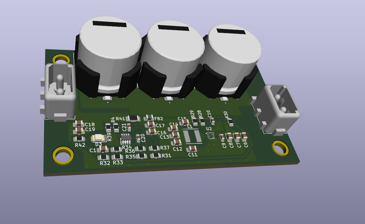
Did some work on the auto-switch filament board today. It’s based on the same schematic as before, but with additional rectification and filtering added this time. The mounting holes and overall dimensions are kept identical to my previous filament board, so it can be dropped in as a direct replacement without any mechanical changes.
-
Thanks a lot, JoaMat. Much appreciated.👍 That confirms my understanding.
-
@JoaMat I have a quick question regarding the servo. Once the servo is in place, does that mean the cathode resistor and its bypass capacitor are no longer needed, and the cathode is effectively tied directly without local bias components? Or are they still retained in some form? Thanks.
-
I haven’t really followed up on this for a while, but today I did a quick LTspice simulation of the 2A3 stage. With a constant plate current of about 23.8 mA, a 3100 Ω cathode resistor looks like a reasonable bias point (compared to 3300 Ω previously). The operating point itself is stable, and plate dissipation comes out to roughly 7.7 W, well below the 15 W maximum for a 2A3. The resulting plate-to-cathode voltage (Va-k) is around 329 V, which is clearly above the classic 2A3 datasheet limit of 300 V. Based on older/NOS 2A3 specs, this would be outside the safe operating range. Some modern production tubes (for example, the EH 2A3) are rated for a higher Va-k (up to ~360 V), so they may tolerate this operating point without issue. Just wanted to share the simulation results. Please share any 2A3 running data points in reality.
-
Cross-checked the layout of kgsshvcarbon6.1c3cs. Red marked the differences. Nothing wrong with the schematic. Just a couple of caps added to it. And the shrink version Circlotron(CRHV) board has been shipped out from the manufacturer. Will report the result later. kgsshvcarbon6.1c3cs.pdf
-
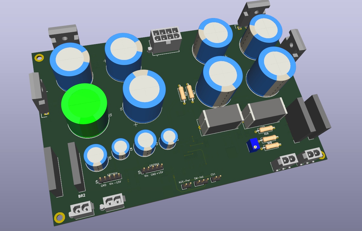
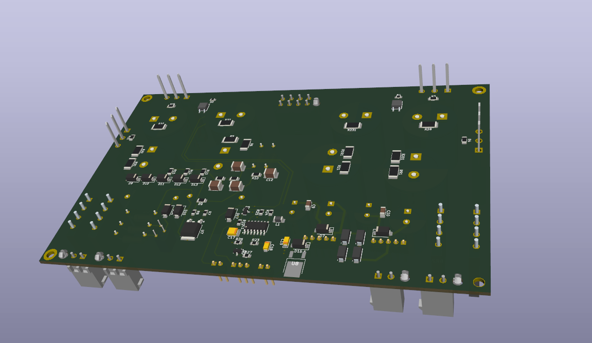
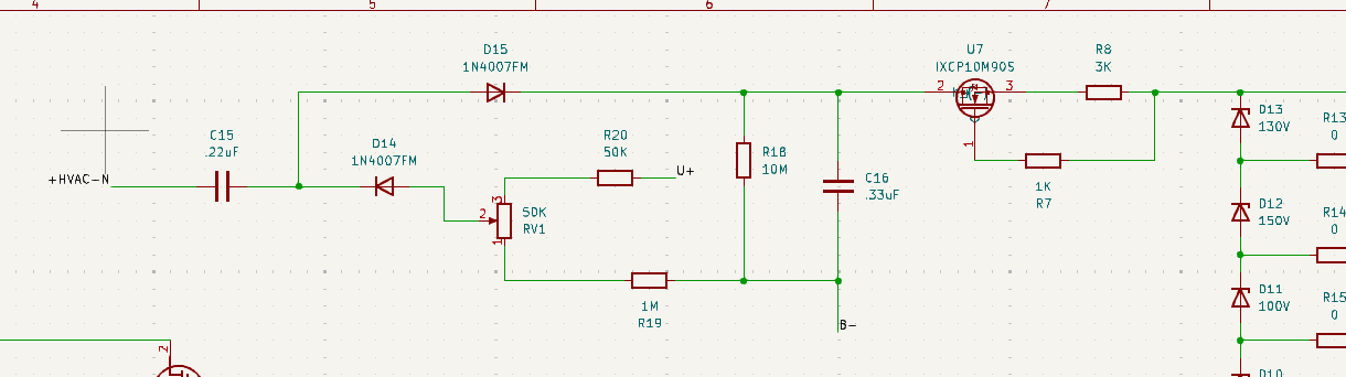
I’ve mostly finished the layout at this point. The current board size is 107 mm × 166 mm, and it integrates the following onto a single PCB: Bias GRLV interface Circlotron PSU interfaces Soft-start circuit Four IXTH6N100 Stand outside. Should be fine w/o heatsinks. Both Circlotron supplies merged into one board. For reference, the original Circlotron PSU boards were roughly 176 mm × 190 mm per board, so the overall footprint has been reduced to well under half the original total area while keeping full functionality. The shrink seems reasonably successful so far. There is one point I’m still not fully confident about (see Fig. 4): C15, left side +HVAC-N — which rectifier bridge should this node reference? In the non-floating implementation, it would naturally reference the rectifier feeding B+. However, once the supply is fully floating, I’m not entirely sure which point should be considered the correct reference for this connection, and I’m unclear which node I should be tying it to. Any clarification on the correct reference point here would be appreciated.
-
Sorry. I didn’t read your post carefully enough the first time. Glad you’ve got a working solution. My current thinking is: instead of keeping Q12 at the very end of the PSU, I’m considering moving it right after the rectifier and bulk filtering, and ahead of the C2M device. For the SMD version, I’m also thinking about adding a STR1550 locally next to the C2M to provide a second layer of current limiting. That said, as mentioned before, similar to something like a 2N3094, but who knows if it works or not. The main goal of the SMD redesign right now is to merge the two circlotron PSU boards into a single board and reduce the overall size by roughly half. If space allows, I’d also like to see whether the 15 V golden reference and the CPC1117 delay / soft-start can be integrated onto the same board. I have some ideas sketched out, but I haven’t started any actual layout work yet.🤐
-
I believe Q12 (IXTH6N100) here is also acting as a current limiter, and it’s a depletion-mode MOSFET. I’ve been thinking about slightly changing its placement: moving it ahead of Q2 (C2M), after the filtering stage. Since the C2M devices are now discontinued, they’re likely to become increasingly difficult to source going forward.
-
What specific differences do you notice after adding the 100 µF caps?
-
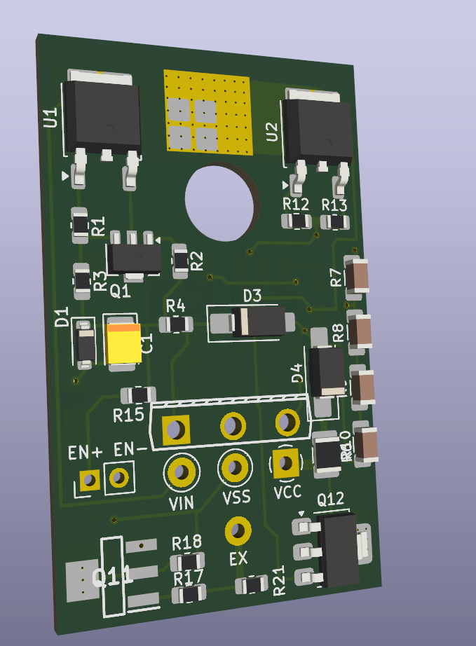
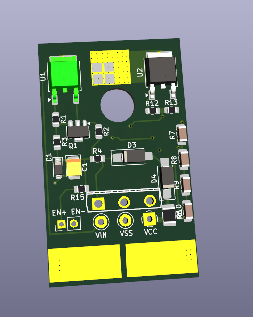
Roughly based on the schematic Kevin provided (Based on the version with the extra 1N4007 diode), I did an SMD layout of the circlotron PSU. Yes, it looks familiar. The layout was adapted from the GRHV SMD board and modified for this application. The board size is 51 mm × 31 mm. The KSC5026 was replaced with STN0214, using a large copper pad underneath for heat dissipation. The 10 Ω / 5 W resistor can also be substituted with 4.7 Ω, which is generally easier to source. Don`t know if the two stn0214s can be replaced by PBHV2160.
-
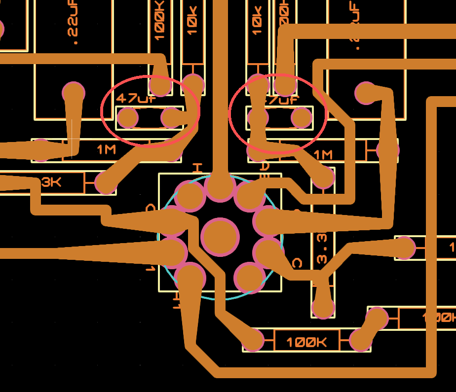
Double-checked the gerber file of the Megatron XL today. It shows 47uf caps to gnd nearby the 12AX7. Don`t know if it should be .47uf instead of the 47. The rerber file name is megatron12vxl3fp ver .27
-
Here you go. I forward the previous pic. Should be visible now.
-
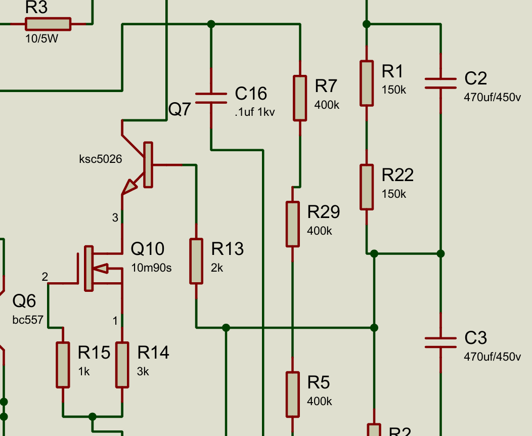
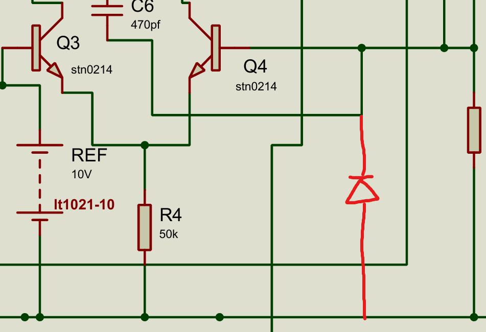
Can we replace the Q7 KSC5026 with STN0214 ? Since someone mentioned it can be replaced in GRHV build. Also, an extra 1N4007 may be good here(photo 2) for further protection i guess. Try to shrink the size of the PCB and see how far we can go.
-
So, like connect the PSU1 + and PSU2 -. Then the remaining - and + from both PSU to the B+ and B-, leave the GND unconnected. Do I understand it correctly?
-
Quick question: how did you connect the floating PSU outputs to B+, B−, and GND in your build?
-
I carefully cross-checked the circlotron schematic against the PCB layout and noticed a few discrepancies between the two. I’m posting them here so others can help double-check the circuit. All the locations where the schematic and PCB differ are marked with red lines in the file. CirclotronV.11.pdf
-
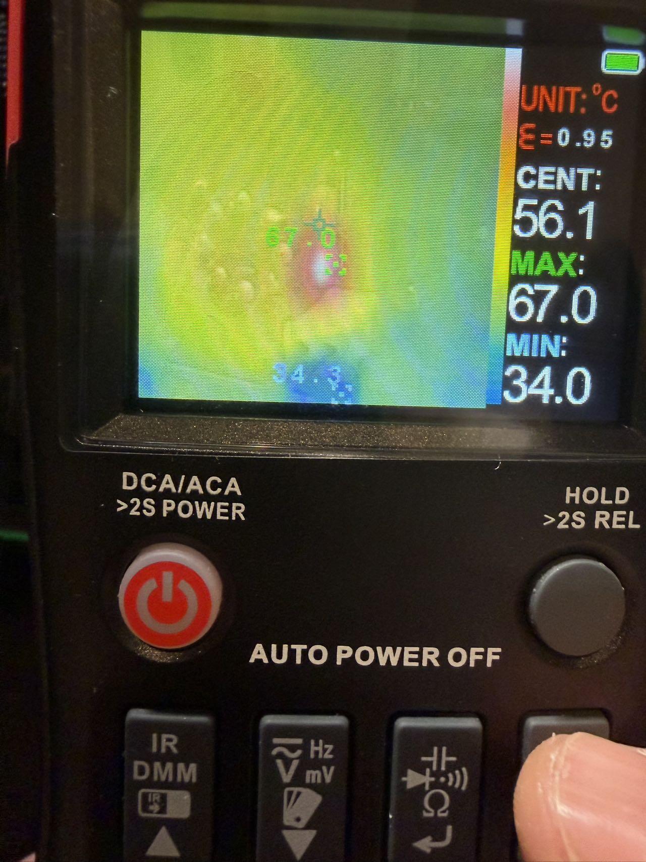
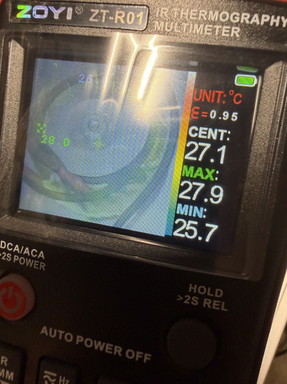
After almost a month of business travel, I finally had some time to follow up on this thread. It’s great to see that the filament PSU design has been making further progress. Today I did a quick and very simple thermal check on a Megatron after about 30 minutes of warm-up using a basic thermal camera: Transformers: max ~28 °C Power supply section: max ~55 °C (MOSFETs + rectifier bridges) 1.5 kΩ resistors under the EL34s: ~67 °C Overall the thermal behavior looks very reasonable and well within expectations.