Shawn
Returning Member
-
Joined
-
Last visited
Everything posted by Shawn
-
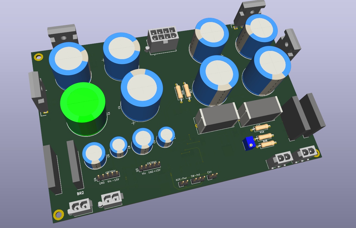
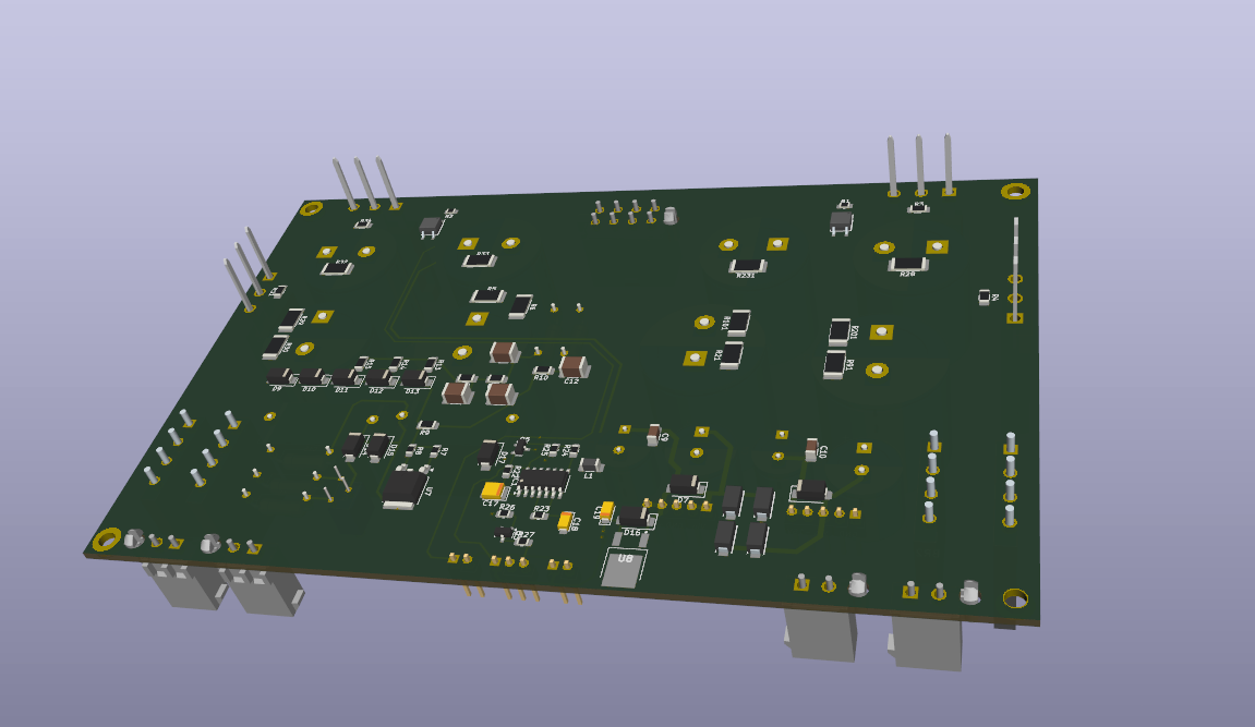
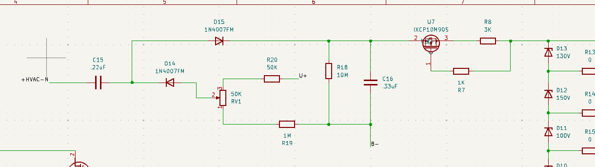
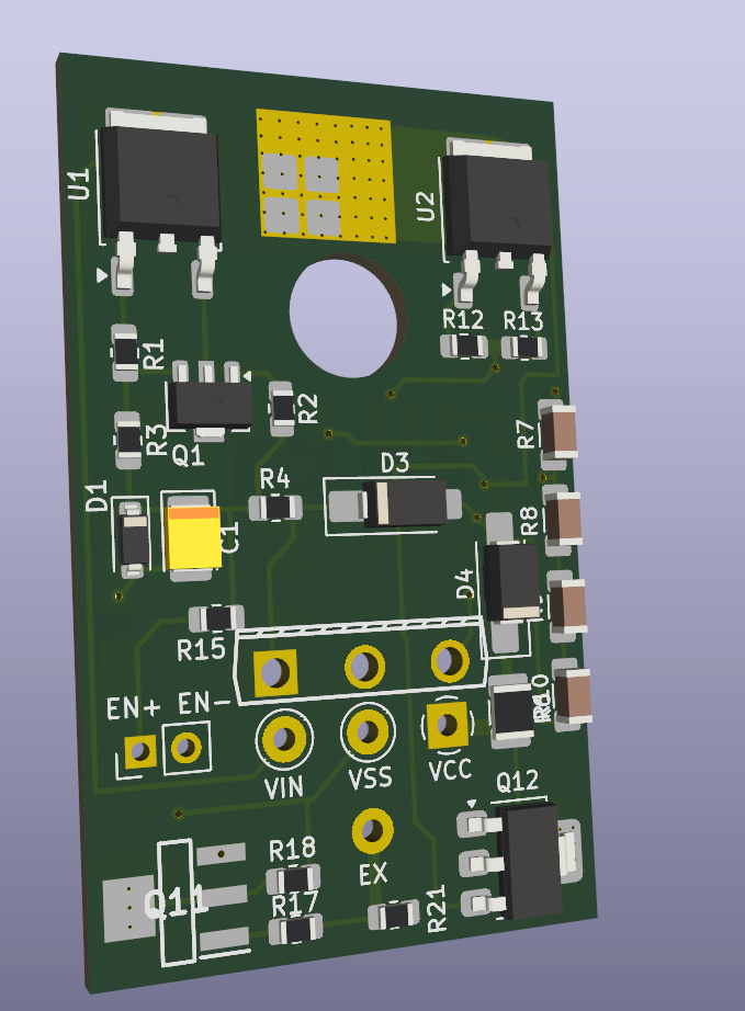
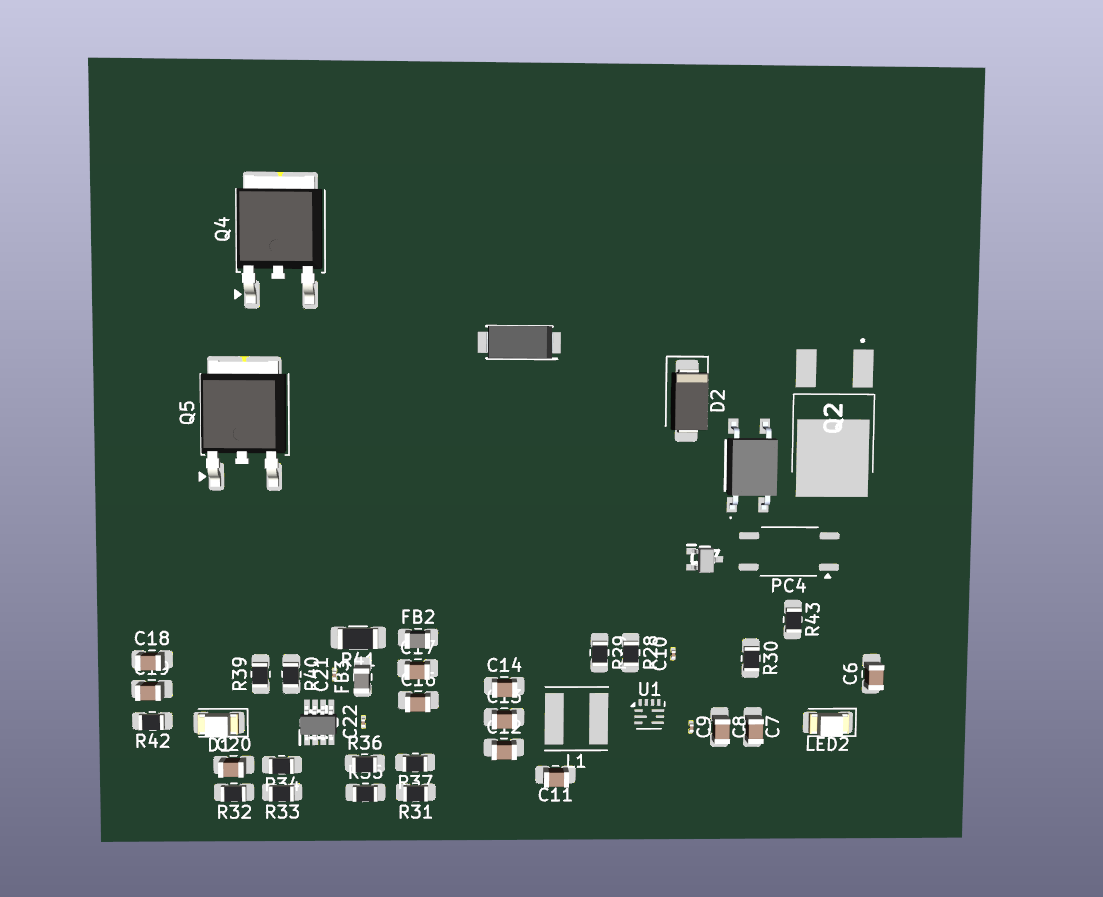
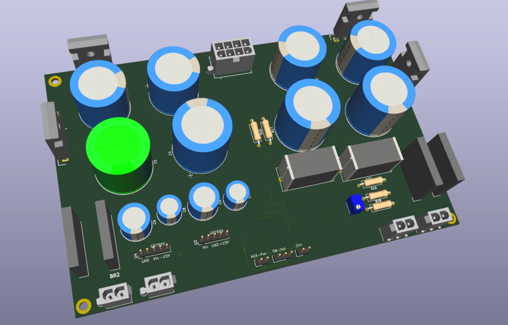
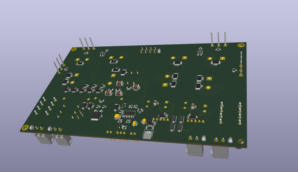
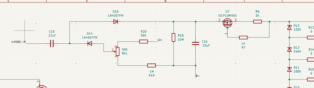
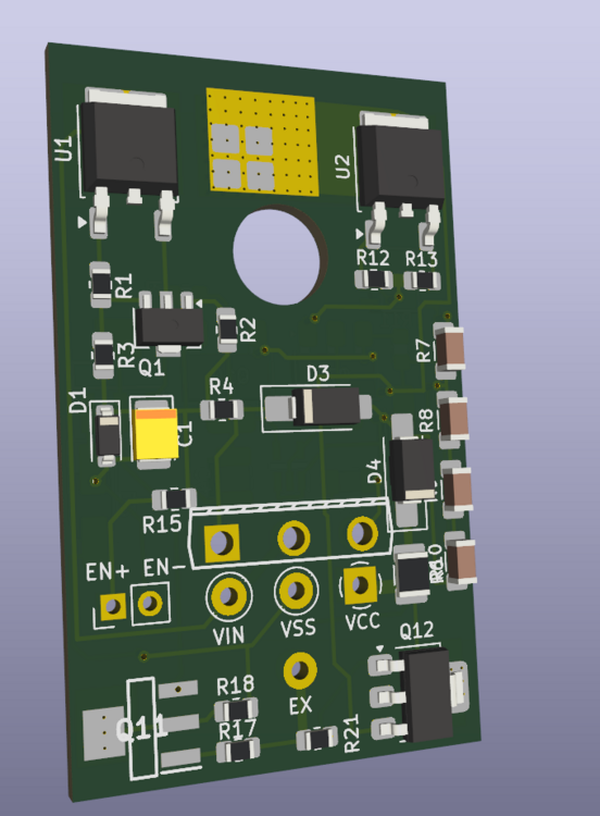
I’ve mostly finished the layout at this point. The current board size is 107 mm × 166 mm, and it integrates the following onto a single PCB: Bias GRLV interface Circlotron PSU interfaces Soft-start circuit Four IXTH6N100 Stand outside. Should be fine w/o heatsinks. Both Circlotron supplies merged into one board. For reference, the original Circlotron PSU boards were roughly 176 mm × 190 mm per board, so the overall footprint has been reduced to well under half the original total area while keeping full functionality. The shrink seems reasonably successful so far. There is one point I’m still not fully confident about (see Fig. 4): C15, left side +HVAC-N — which rectifier bridge should this node reference? In the non-floating implementation, it would naturally reference the rectifier feeding B+. However, once the supply is fully floating, I’m not entirely sure which point should be considered the correct reference for this connection, and I’m unclear which node I should be tying it to. Any clarification on the correct reference point here would be appreciated.
-
Sorry. I didn’t read your post carefully enough the first time. Glad you’ve got a working solution. My current thinking is: instead of keeping Q12 at the very end of the PSU, I’m considering moving it right after the rectifier and bulk filtering, and ahead of the C2M device. For the SMD version, I’m also thinking about adding a STR1550 locally next to the C2M to provide a second layer of current limiting. That said, as mentioned before, similar to something like a 2N3094, but who knows if it works or not. The main goal of the SMD redesign right now is to merge the two circlotron PSU boards into a single board and reduce the overall size by roughly half. If space allows, I’d also like to see whether the 15 V golden reference and the CPC1117 delay / soft-start can be integrated onto the same board. I have some ideas sketched out, but I haven’t started any actual layout work yet.🤐
-
I believe Q12 (IXTH6N100) here is also acting as a current limiter, and it’s a depletion-mode MOSFET. I’ve been thinking about slightly changing its placement: moving it ahead of Q2 (C2M), after the filtering stage. Since the C2M devices are now discontinued, they’re likely to become increasingly difficult to source going forward.
-
What specific differences do you notice after adding the 100 µF caps?
-
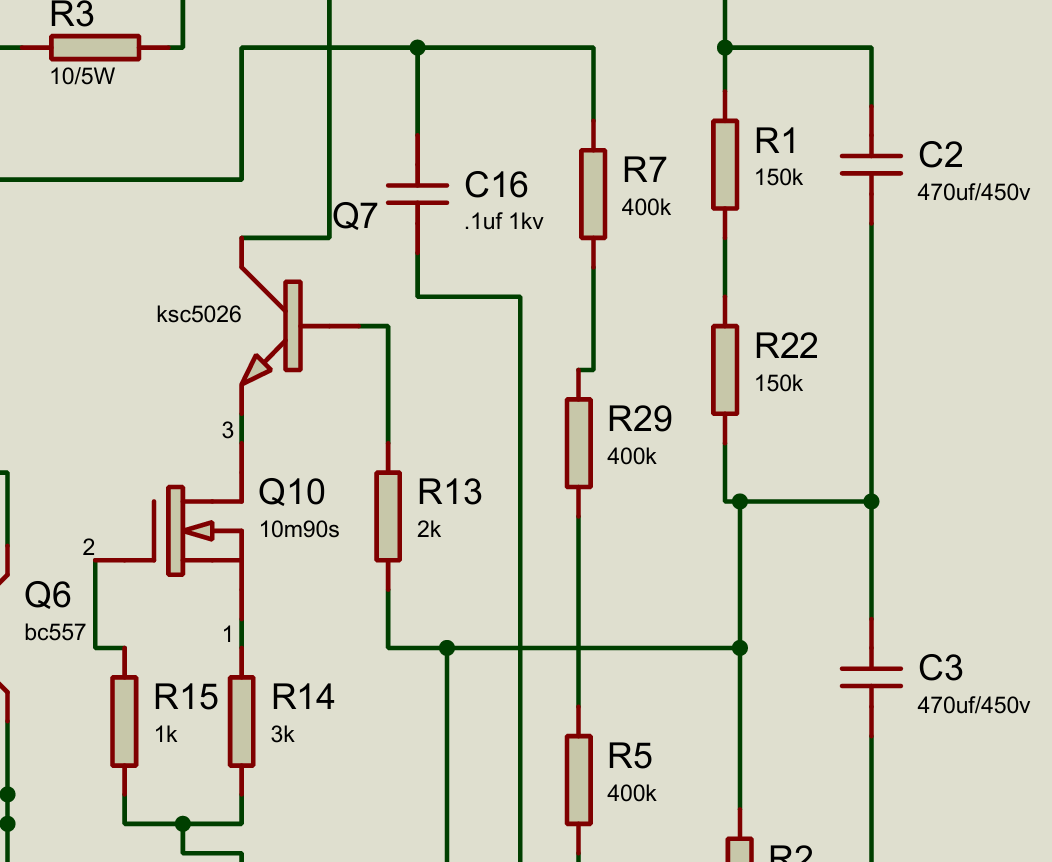
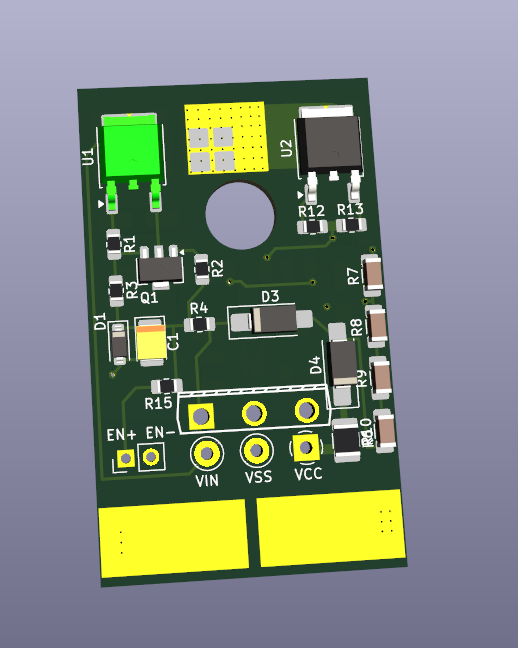
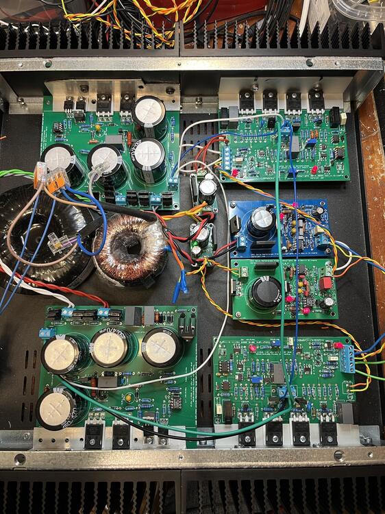
Roughly based on the schematic Kevin provided (Based on the version with the extra 1N4007 diode), I did an SMD layout of the circlotron PSU. Yes, it looks familiar. The layout was adapted from the GRHV SMD board and modified for this application. The board size is 51 mm × 31 mm. The KSC5026 was replaced with STN0214, using a large copper pad underneath for heat dissipation. The 10 Ω / 5 W resistor can also be substituted with 4.7 Ω, which is generally easier to source. Don`t know if the two stn0214s can be replaced by PBHV2160.
-
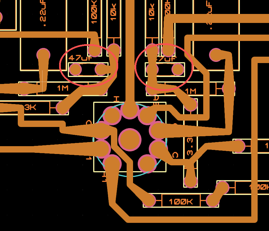
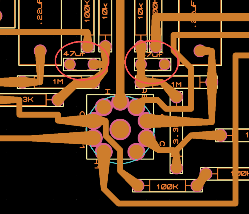
Double-checked the gerber file of the Megatron XL today. It shows 47uf caps to gnd nearby the 12AX7. Don`t know if it should be .47uf instead of the 47. The rerber file name is megatron12vxl3fp ver .27
-
Here you go. I forward the previous pic. Should be visible now.
-
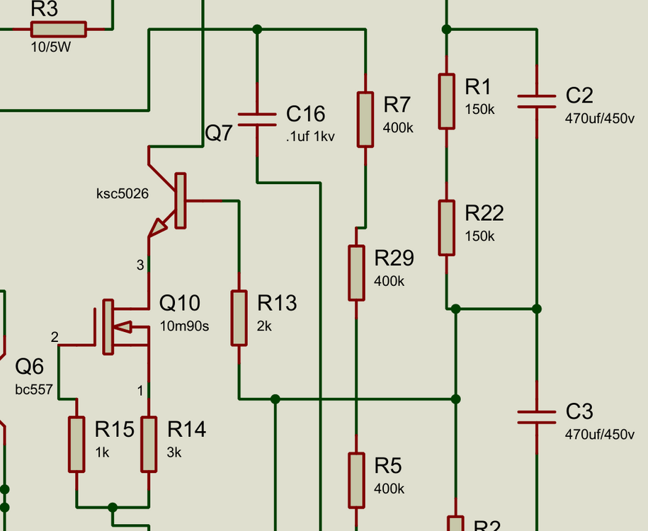
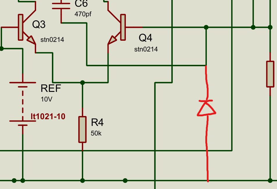
Can we replace the Q7 KSC5026 with STN0214 ? Since someone mentioned it can be replaced in GRHV build. Also, an extra 1N4007 may be good here(photo 2) for further protection i guess. Try to shrink the size of the PCB and see how far we can go.
-
So, like connect the PSU1 + and PSU2 -. Then the remaining - and + from both PSU to the B+ and B-, leave the GND unconnected. Do I understand it correctly?
-
Quick question: how did you connect the floating PSU outputs to B+, B−, and GND in your build?
-
I carefully cross-checked the circlotron schematic against the PCB layout and noticed a few discrepancies between the two. I’m posting them here so others can help double-check the circuit. All the locations where the schematic and PCB differ are marked with red lines in the file. CirclotronV.11.pdf
-
-
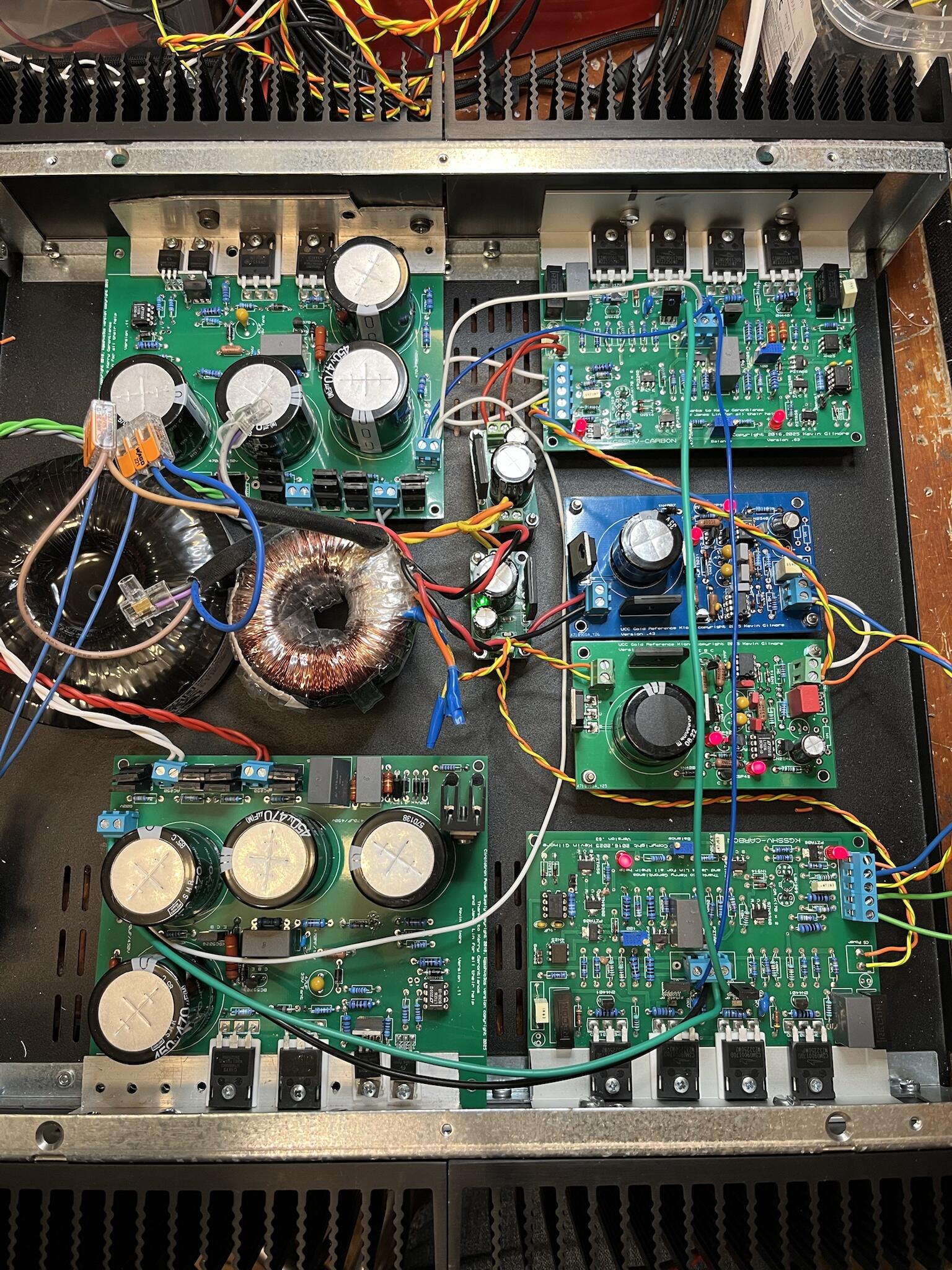
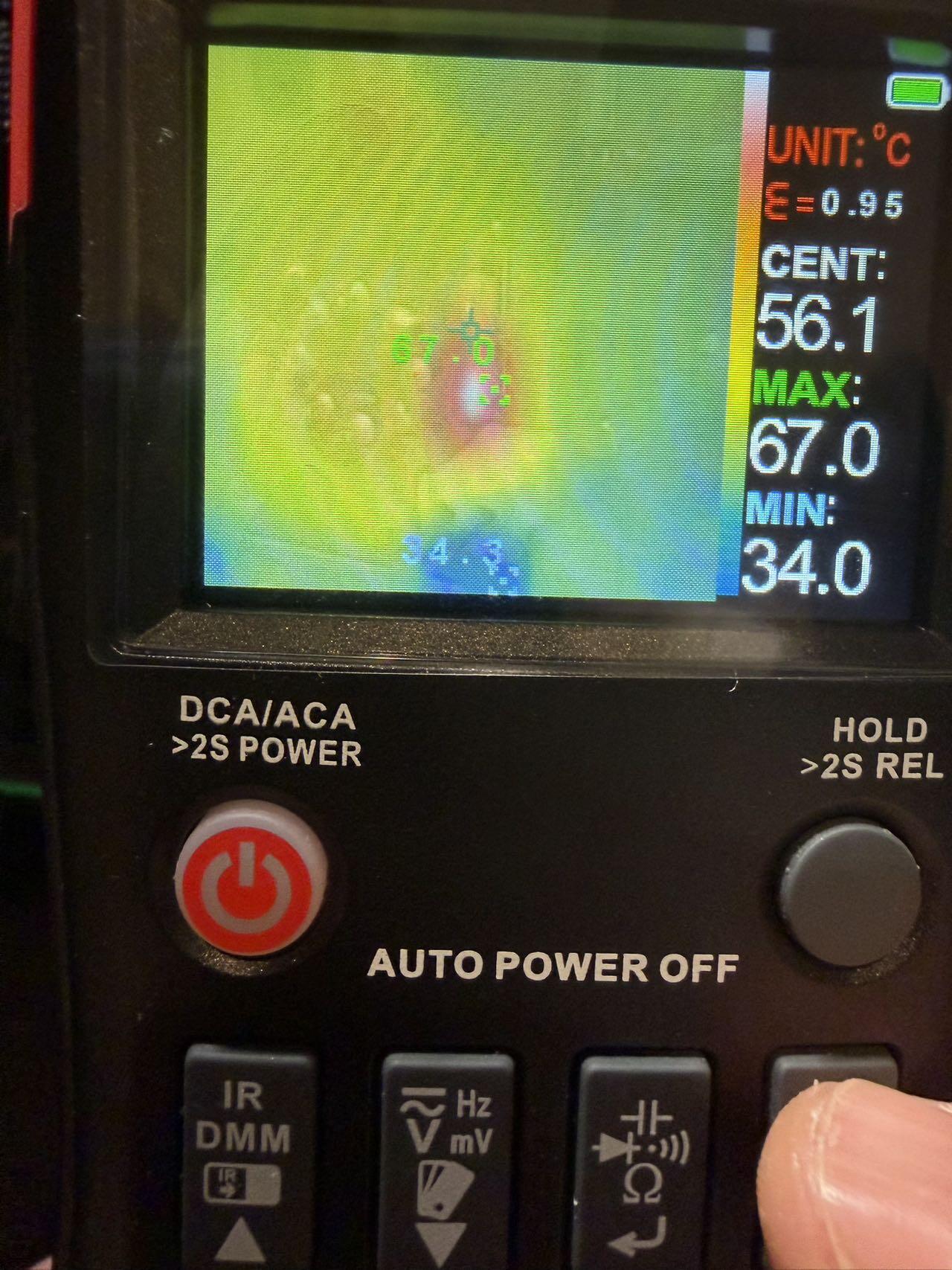
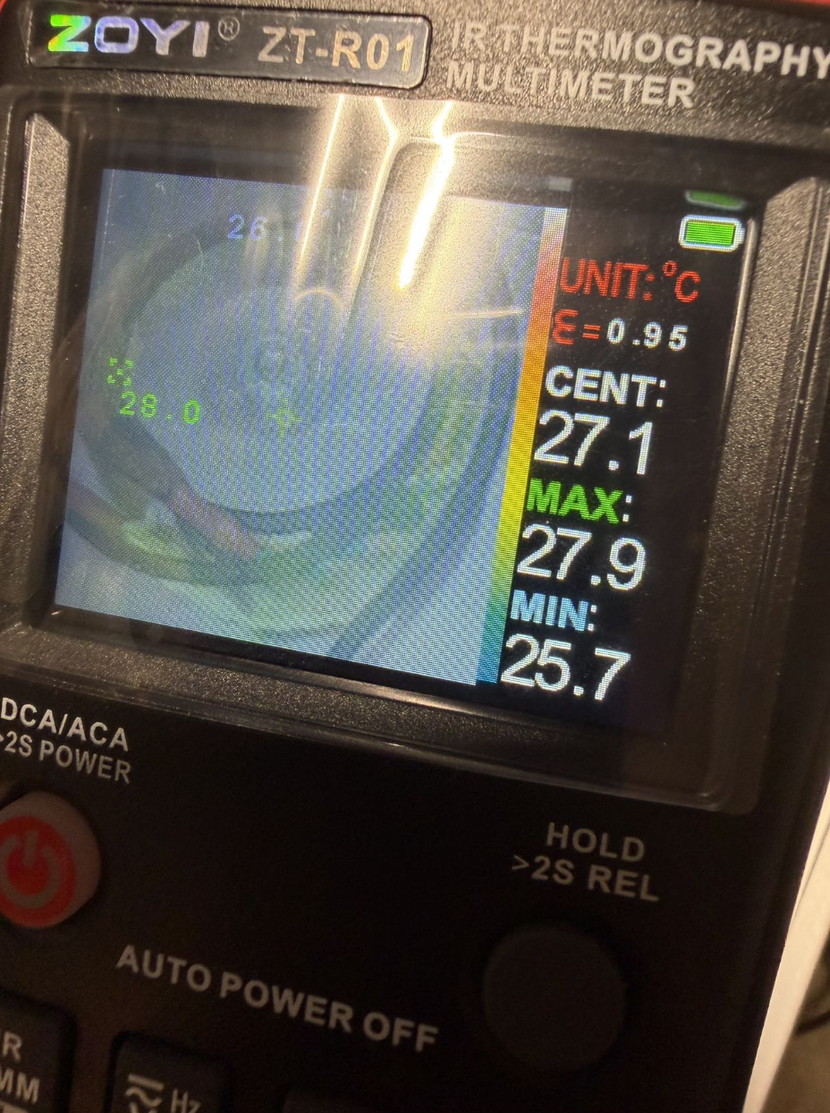
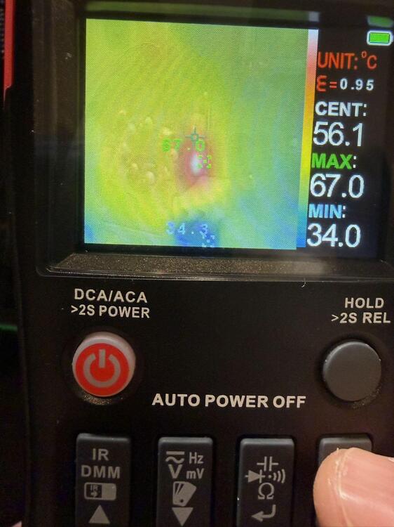
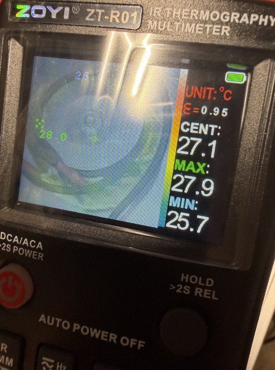
After almost a month of business travel, I finally had some time to follow up on this thread. It’s great to see that the filament PSU design has been making further progress. Today I did a quick and very simple thermal check on a Megatron after about 30 minutes of warm-up using a basic thermal camera: Transformers: max ~28 °C Power supply section: max ~55 °C (MOSFETs + rectifier bridges) 1.5 kΩ resistors under the EL34s: ~67 °C Overall the thermal behavior looks very reasonable and well within expectations.
-
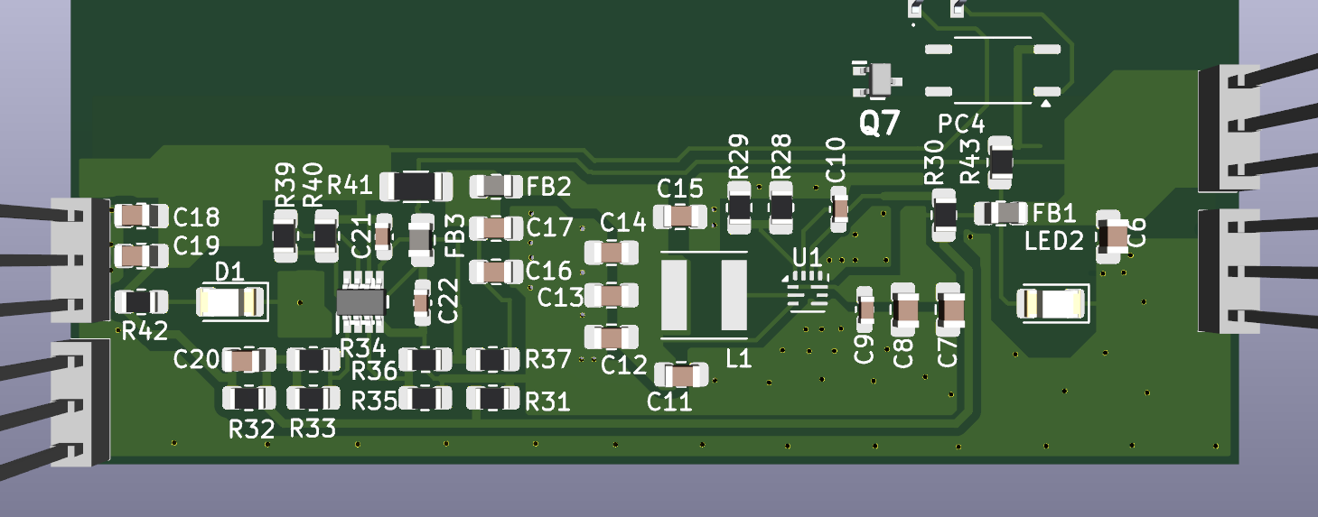
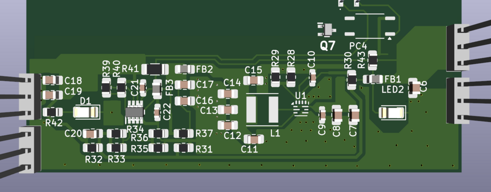
Eagle eye! Good catch. I’ve updated the image and added the missing R41–FB2–C16–C17 connections as you indicated. Thanks!
-
I checked your schematic and compared it with your previous hardware photos, then corrected a few small errors(From both sides of us). Here’s the updated layout. It’s basically reverse-engineered from the pictures you posted earlier. I also derived the schematic from it, but it’s quite messy at the moment. If anyone’s interested, I can post that version as well.
-
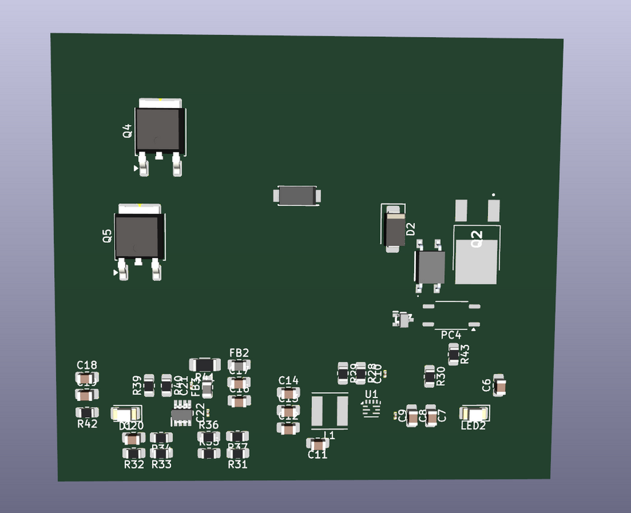
Thanks to @JoaMat for posting the 2A3/300B auto-switching filament supply. Although the picture isn’t very clear, I’ve been trying to figure out how it actually works. I roughly recreated the layout (still very preliminary, no routing yet. So please note it may/does contain errors. From what I can tell, the circuit likely uses the voltage comparator on the left to sense the voltage drop across a 0.05 Ω current-sense resistor, distinguishing the different filament currents of 2A3 vs. 300B. The two optocouplers at the upper right appear to be controlled by that comparator and might handle auto-bias adjustment. This is still an early interpretation. I’ll keep updating as I make progress or manage to get a cleaner schematic. That looks really interesting. Can I ask a quick question: Are the two trimmers on top each setting the grid voltage vs. plate current, or are they controlling the grid potential of each EL34 individually? Also, is the 120 V GRHV section meant to supply the bias/grid voltage reference for the output tubes?
-
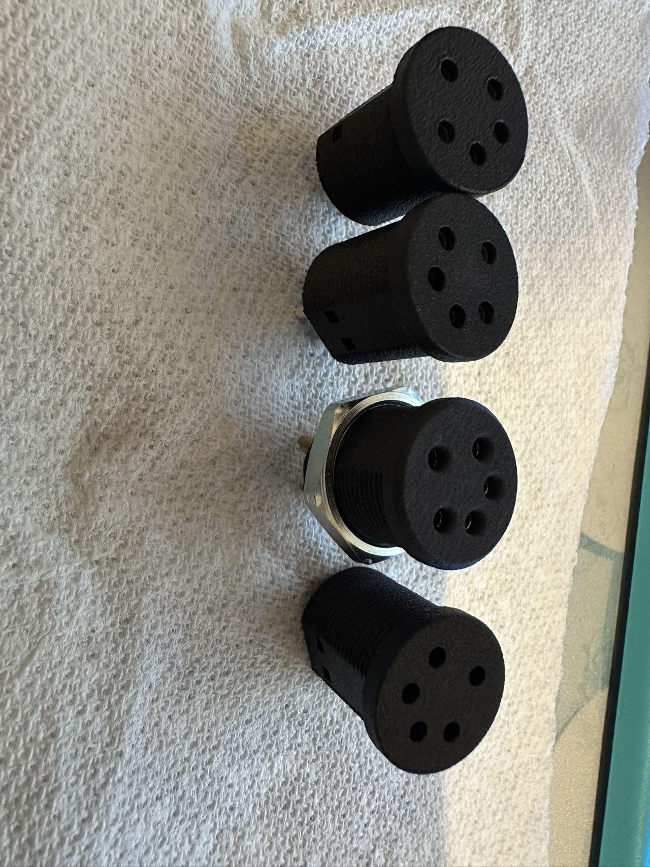
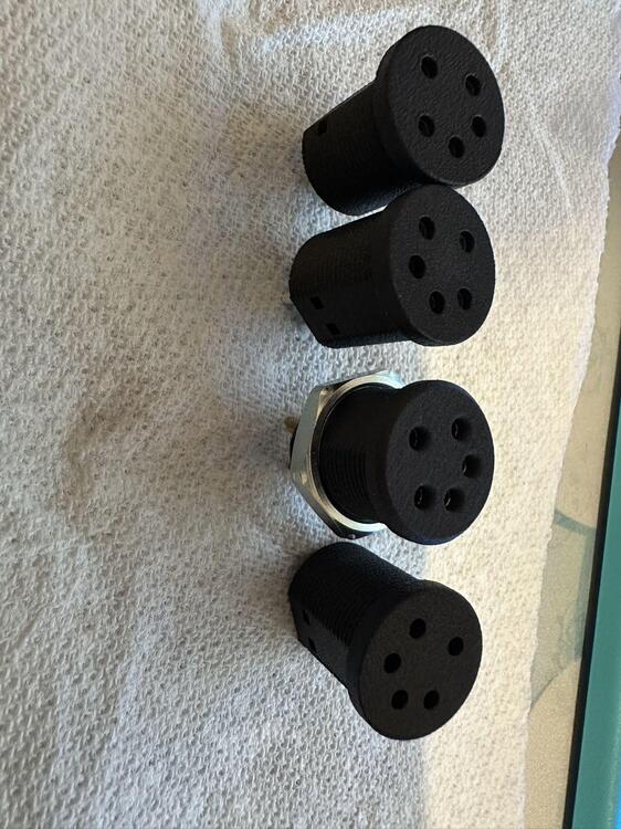
The pin hole diameter is roughly 2–4 mm, but one thing to keep in mind is that 3D printers, especially hobby-grade ones tend to have pretty poor dimensional accuracy. A nominal 2 mm hole can easily shrink to around 1.2–1.4 mm, so you’ll need to experiment a bit to dial in the correct size for your printer and filament. Yes, I’m using the threaded collet-style socket. It’s simple and works fine, but honestly, I think the mounting method Joamat posted above is better since you don’t have to fuss with rotating and aligning the jack during installation. The HA-3FXX is a good choice. The only downside is that it doesn’t have a gold-plated version. Hopefully, someone can find a gold-plated alternative. I’ll stick with my current version for now until I get the chance to make a screw-fixed version. And if enough people are interested in the current version, a group buy could definitely be possible.
-
I did some test prints of Stax jacks with different pin-hole diameters. As you can see, they are obviously 3D-printed, but the material is rated to withstand up to 195 °C. So far I’ve been using them for about 2 years without any issues.
-
Alright, here are the quick results. Case 1: Rupper = 1500, Rlower = 3200, G-pot = 10 kΩ (set at ~10%). Va ≈ –1.7 V, Vgk ≈ –85.6 V, Plate Voltage = 362.2 V. Case 2: Rupper = 1200, Rlower = 2600, G-pot = 10 kΩ (set at ~10%). Va ≈ 3.3 V, Vgk ≈ –85.3 V, Plate Voltage = 367.4 V. I didn’t measure at 38 mA, since I wasn’t sure whether the EL34 would be overloaded, and I also don’t have the right resistor configuration at hand (Vishay Dale parts are really not cheap). That said, you can see that in both cases the plate voltage stays in the 400 V max cell, which in theory should not be dangerous, but who really knows.
-
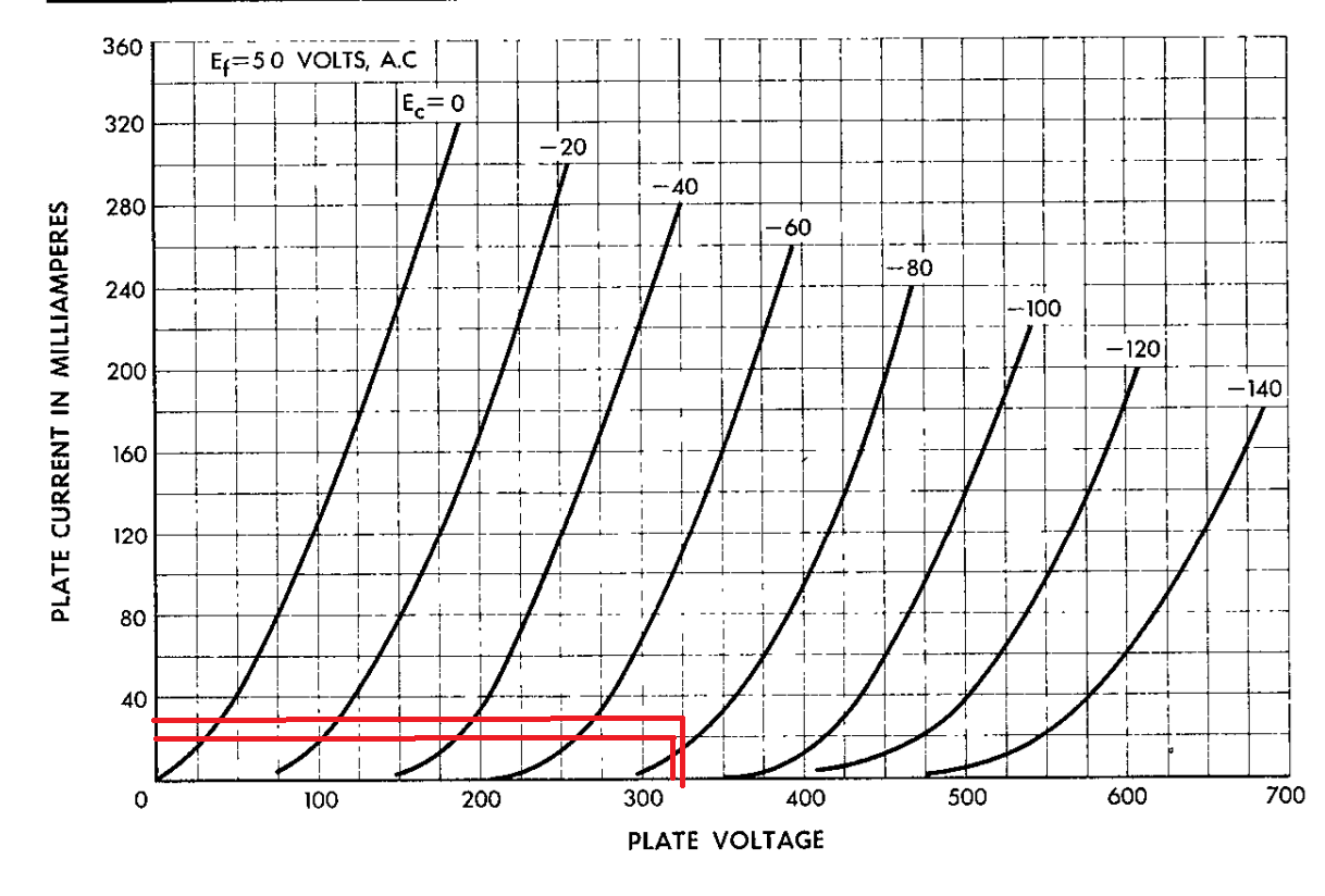
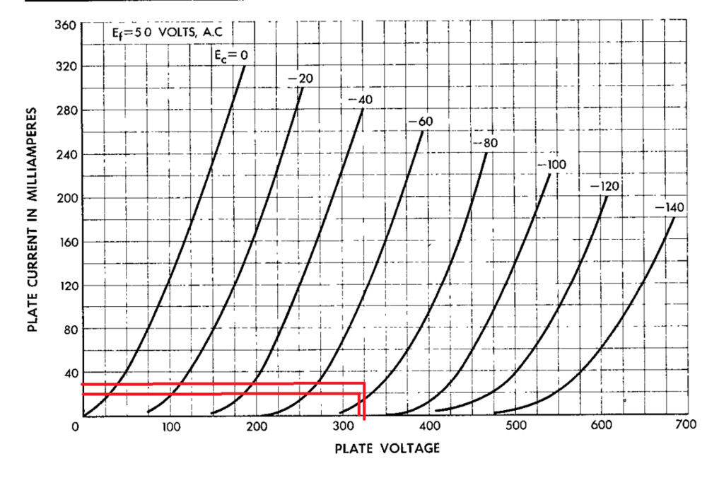
After some rounds of trial and simulation, I thought I’d put together a rough guide for setting the 300B operating point, mainly to make life easier when dialing things in. Given static operating currents: 34.3 mA → Rk = 2160 Ω, Vgk = –73.7 V, Grid pot = 10 kΩ, set around 10%. 23.8 mA → Rk = 3200 Ω, Vgk = –75.8 V, Grid pot = 10 kΩ, set around 10%. Plate voltage check (with Va = 0 V target): At 34.3 mA → Plate Voltage = Va – Vk = 0 – (–325.9) = 325.9 V. At 23.8 mA → Plate Voltage = 323.8 V. By matching these points against the 300B characteristic curves (see the red-line markers in the attached graph), the theoretical Vgk comes out roughly between –70 V and –75 V, which lines up with the measured –73.7 V and –75.8 V. From the curves, the 34.3 mA point looks more linear. Pushing current further could be even better, but that depends on whether the EL34 can handle it safely and whether the PSU has enough overhead. All of these measurements are under a ±400 V supply. The 300B datasheet gives a max plate voltage of 400 V (though some manufacturers claim 450 V). On the XL build, with 400 V rails, the plate voltage is about 335 V, and still within a safe zone. I haven’t confirmed the behavior at 450 V rails, but I’d expect plate voltage around ~380 V, which starts to get a bit risky. If anyone’s interested, I can run tests at 450 V and report back the voltages at each node.
-
Thanks for the report. May I ask if you are using a GRHV supply? And is your transformer secondary around 330 VAC for the ±400 V rails? I just want to rule out whether my drop is caused by insufficient transformer headroom rather than the current limit itself.
-
Thanks a lot for the hint. Since I haven’t ordered the test resistors yet, I’ll probably need some time before I can try it out on a new build. But for today I did some measurements on the current operating point, and hopefully these numbers help add to the pool of data. For easy comparison, I’ll use your same format. Based on the WE datasheet, I think both of our Vgk values are on the shallow side, but as Kevin has mentioned, modern 300Bs vary a lot, so I’m not 100% sure if this is correct. It might make sense to raise the current to 33–34 mA, in which case the required Vgk would move down (according to the WE300B datasheet, Vgk at 34 mA / 400 V is about –90 V). My expectation is that as the current goes up, the offset also increases and Vgk becomes more negative. To bring the offset back to 0 V, you’d adjust Vg, but when Vg changes, Vgk may swing more positive again. If possible, it would be great if you could validate this in LTspice. One more observation: with ±400 V supply, under load I measured about 389 V. I’m not sure if this is simply normal drop or if my current-limit is engaging. Could you let me know if your ±400 V rails drop as well? If yours stay right at 400 V, then I probably need to tweak my current-limit detection resistors.

-
Thanks for your reply. I plan to test different combinations of static current and cathode resistor values to better understand how they interact. If I get some results I’ll come back and share them. For now, I’m planning to try around 27–30 mA of static current. It’s a bit difficult to find high-precision resistors around 1.2 kΩ, so on the cathode side I’ll probably increase to about 8 kΩ and see how it behaves.
-
About the pin choice. I think this one might be closer to the original tube pins: MPN:6835-0-00-15-00-00-44-0 https://www.mouser.com/datasheet/2/273/MMMC_S_A0004813843_1-2556643.pdf I haven’t ordered it yet to confirm, but maybe it helps you. Also, I’d like to get your advice: At 400 V / 22 mA, would you consider setting Vgk around –95 V a good operating point? I’m also thinking about increasing the static current to around 27–30 mA. From what I see, the EL34 max plate dissipation is ~25 W. At 400 V / 30 mA, that’s only about 12 W, so it looks safe on paper. I’d love to hear your thoughts on this.
-
Yes, I noticed that too. But I found those machining marks only on the inner rear panel, left and right sides. The rest of the chassis looks clean. I’m pretty sure they just used 3-axis machining, which is still miles better than what I could do on my home-garage CNC. Of course, 5-axis is another story, and I’ve been thinking about designing some more complex curved surfaces where 5-axis paths would actually make sense. Overall though, I’m quite happy with how this chassis turned out. I haven’t yet checked all the PCB mounting hole positions against the boards, but so far it looks promising.