Shawn
Returning Member
-
Joined
-
Last visited
Everything posted by Shawn
-
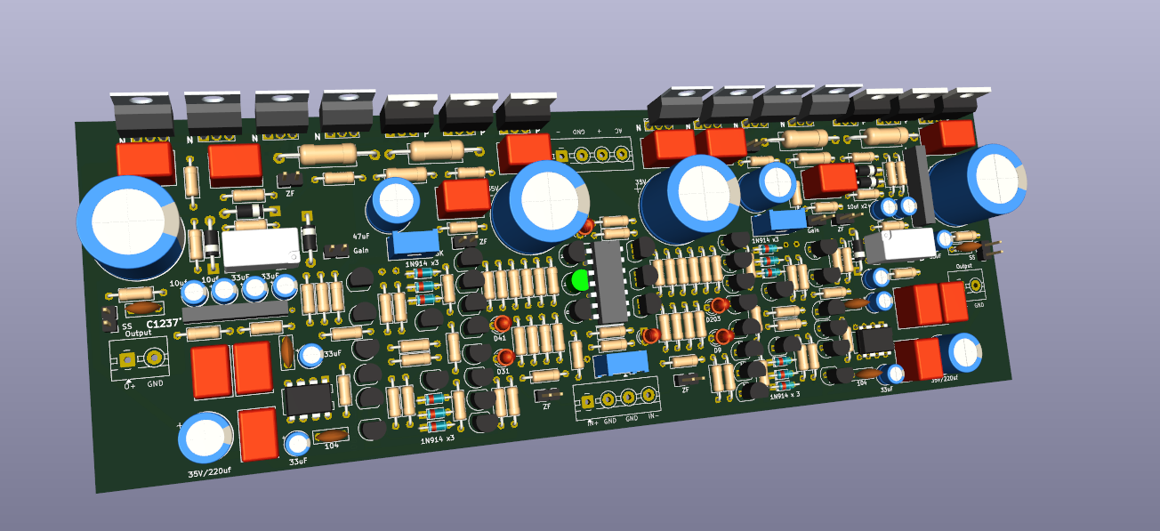
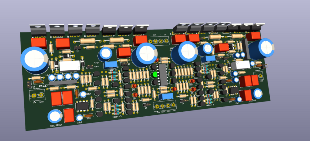
Working on a shrunk CFA3 layout this week, here is what it looks like. Haven`t tested it yet. The dim is about 8.6 inches * 3 inches per channel. Not small enough, but I bet someone can make it better by SMDing.
-
-
-
I didn`t check the schematic. However, the input resistors(Signal input) shouldn`t be a probably if you go with 15k or 20k.
-
JoaMat always helps. I appreciate the input regarding the 2N3904. I've been considering a modification to handle higher output current more safely. Would it be feasible to add an IXTP08N100D2 (Depletion Mode MOSFET) before the C2M1000170D to serve as a hardware current limiter? Drain of IXTP08N100D2 connects to the Source of C2M1000170D (main current path). Source of IXTP08N100D2 connects to a sense resistor Rs, then to GND. Gate of IXTP08N100D2 is tied to GND (0V) or through a simple RC filter to mitigate noise. The current limit would then be: I = Vgs(th)/Rs. Would this be a viable approach to implement a basic current limiter before the C2M1000170D, or would there be better alternatives? Datasheet attached below: https://www.mouser.com/datasheet/2/240/media-3320804.pdf
-
MLA, Thank you for the reference. Since the C2M1000170d is ending the life cycle, I don`t want to trash them.😅 I may just go with the universal power supply which was used on Megatron before. 2n3904 current limiters needed to remove for the universal supply. I`m wondering if the 2n3904s in GRHV do the same purpose? if yes, can we remove them to increase current? The single universal power supply worked fine on my previous Megatron build(Each El34 draw about 27ma). And I assumed each 300B draw 33mA as Kevin mentioned it is the sweet point for 300B. Don`t know if I calculate it correctly.
-
Finally, I have time to hand in the Megatron XL. Having some questions here. What`s a decent static plate current and voltage for 300B? For the tube rectified power supplies, can we do a solid-state rectifier instead of the GZ34/EZ81? Assumed we have other soft-start high-voltage circuits populated. I'm wondering if it's possible to use the Golden Reference HV supply to provide ±450for XL. Does anyone know if the current capability is sufficient? I'm concerned the total load might be too much for this PSU.
-
Funny enough, I was still thinking about how to do the layout just last night—and then today I saw Kerry’s SMD version that Jomat shared. I have to say, it’s a really beautiful layout. I didn’t expect it could be made that compact, really impressive work. I’m planning to make another version inspired by Kerry’s approach. At the same time, I also ordered PCBs based on the old layout to revisit the process I went through back then. Yes, I remembered the one you posted somewhere in this thread. Don`t know if the MPSA06/56 can replace the MPSW06/56 since the power rates are different.
-
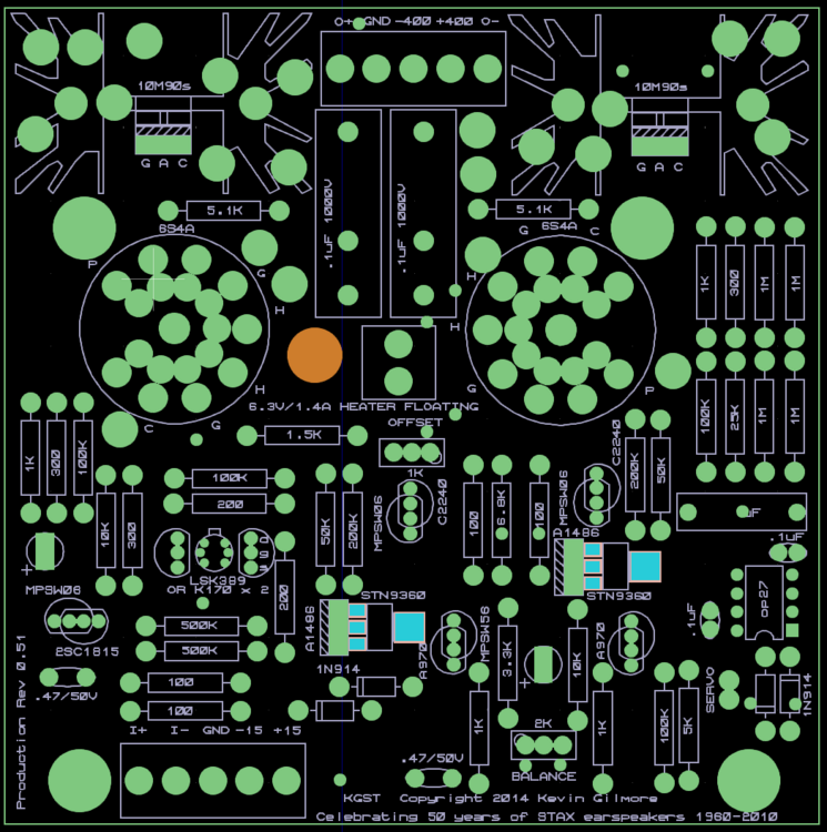
The layout referred to this(kgst-miniv05). Didn`t find the DN2540 in this version. DN2540 version added to the previous post. Q1 (MPSA/W06) can be replaced by 2SC3324. Q4 and Q6 (MPSW/A56) can be replaced by HN4A51. Q5 and Q7 (MPSA/W06) can be replaced by HN4C51.
-
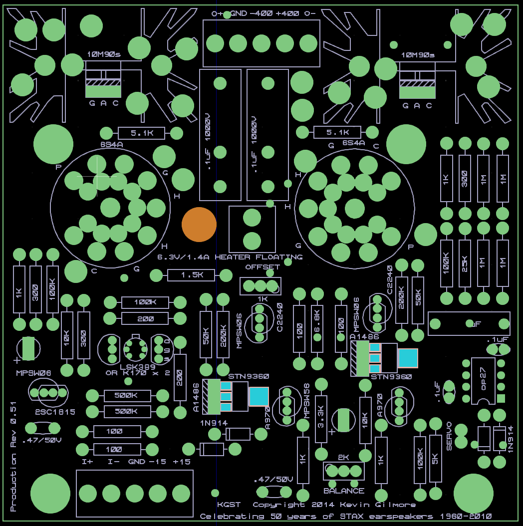
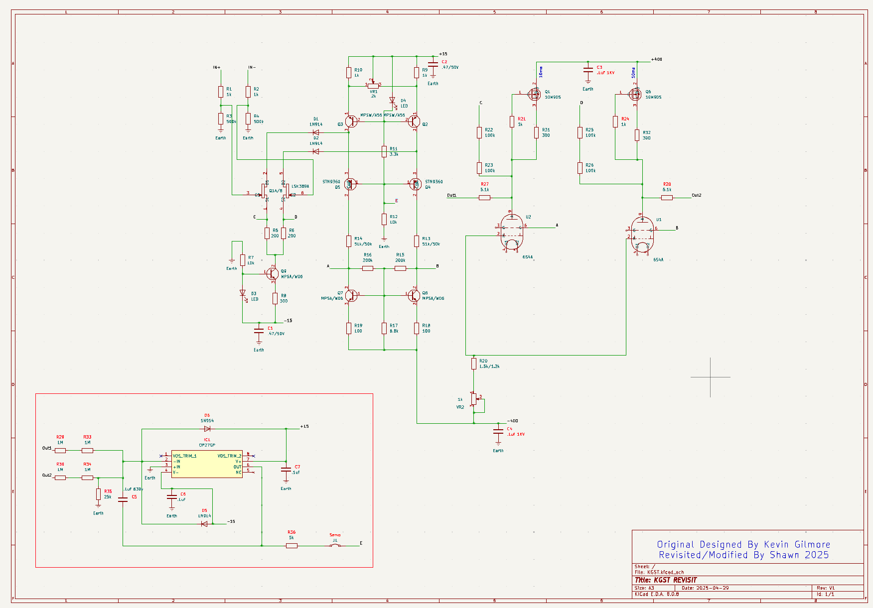
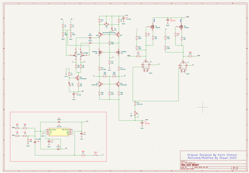
Time really flies — it's been over 10 years since the KGST first came out. KGST was one of the very first DIY electrostatic amps I ever built, and it's still one of my favorites today. Recently, I noticed that the schematic in the Stax Mafia Google Drive has diverged quite a bit from the latest version of the KGST PCB layout. So, I decided to take this opportunity to redraw the schematic based on the newest KGST layout. Hopefully, this will be useful to anyone who needs a fresh reference. Please double-check the schematic before using it — there might still be mistakes. Component numbers follow the original KGST schematic as much as possible. New parts are numbered sequentially. Changes from the old schematic are marked in red The servo section has been added Obsolete parts like C2240//A1486/2SC1815 have been replaced with currently available ones Attached below is the schematic. Next step: I'm planning to attempt a shrunk-down version of the KGST layout, inspired by @JoaMat great work. KGST_2025.pdf KGST_DN2540_2025.pdf
-
Correct me if I am wrong. The Ground Pin(Pin1) has been connected to the XLR socket shell by default by the manufacturer in some cases. This way, the ground pin should be left unconnected to avoid a looping ground. In this case, the loop may be like this: XLR(Pin 3)-> AMP signal ground - > L bracket - > chassis -> XLR(Pin 3). I just realised the L-bracket is isolated to the signal ground, so it should be fine.🤐 I assumed the amp chassis ground wires are connected to the PSU chassis somewhere, and the amp signal grounds are merged with the XLR ground, and then connected to the PSU power supply ground somewhere.
-
-
-
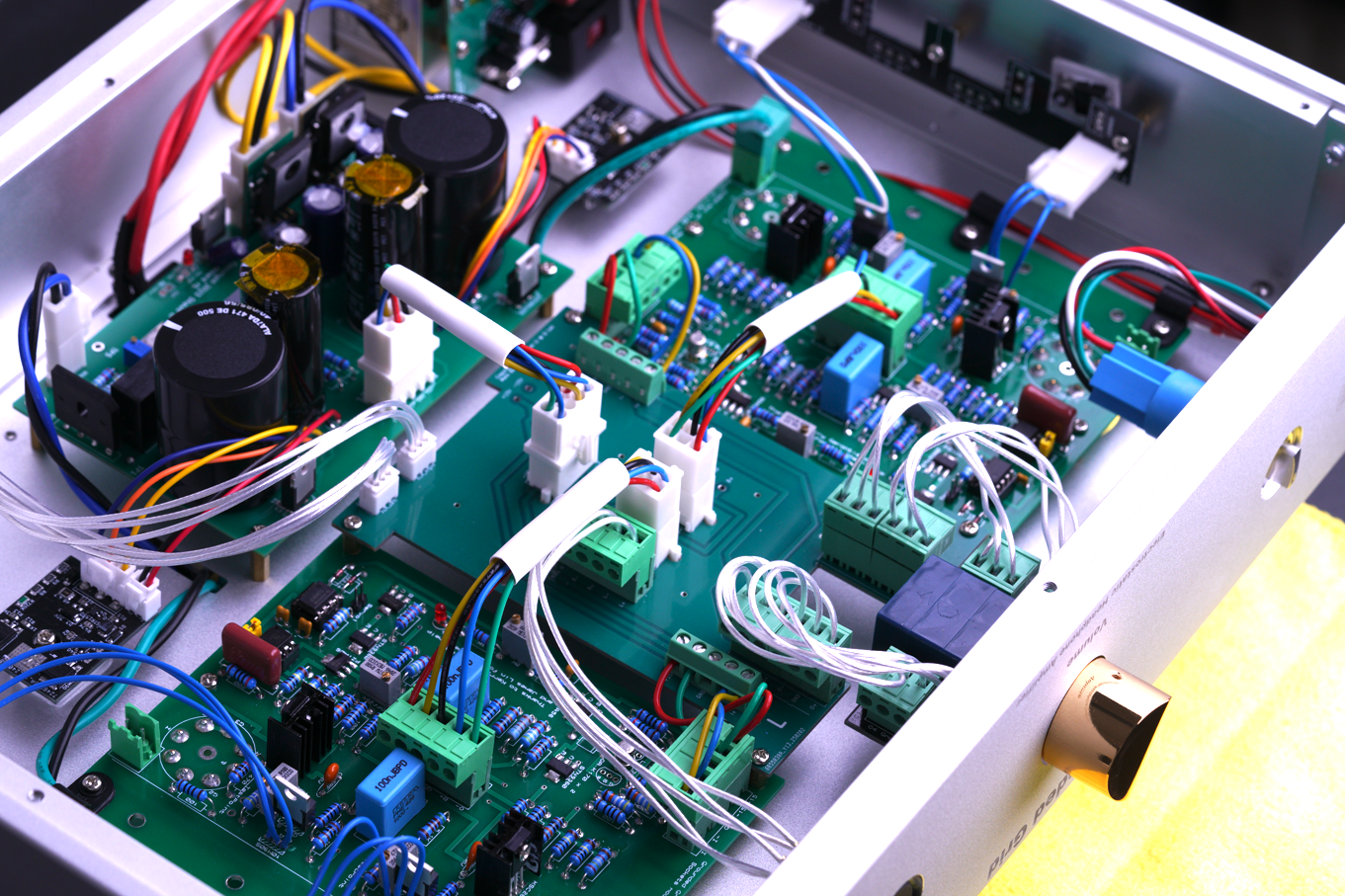
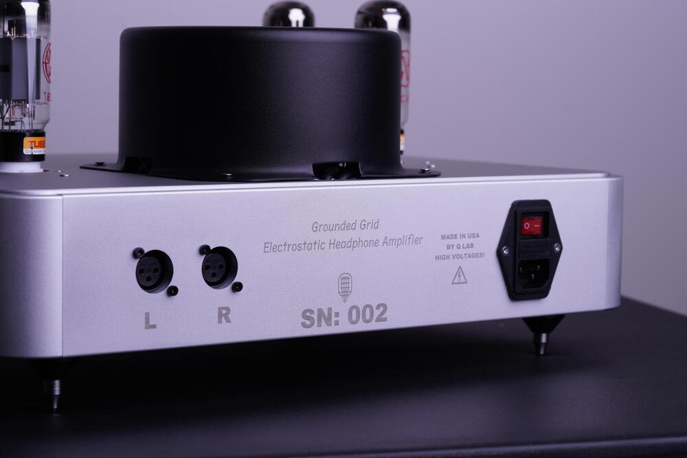
Three weeks later, here is the outcome. A single enclosure all-in-one with GRHV and GRLV with high voltage and heater soft-start. The 10M90S is attached to the side wall, and thanks to the large size of the metal, the temp is about 104℉(40 ℃) after 1 hour. The only thing is I made the mistake of the main soft start module(the one on the power outlet), which makes it only functional when you use the back power switch. In this way, I keep the front power switch on all the time to avoid the ripple current. Still have a huge room to be improved. Planning to add a DC power supply for the heater for the DHT version, as well as the flashing soft start indicator.

-
-
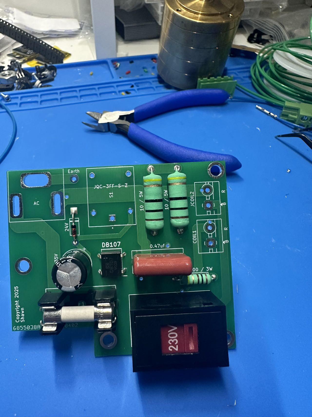
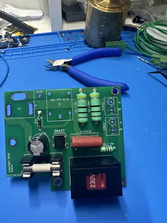
Making a soft starter module with switchable voltage function. No screws required if attached to the AC socket directly.
-
So complicated. Like the volume mute function.
-
Yes. The machine is from Snapmaker, and I am planning to get the Langmuir. Links here. https://www.snapmaker.com/en-US https://www.langmuirsystems.com/mr1
-
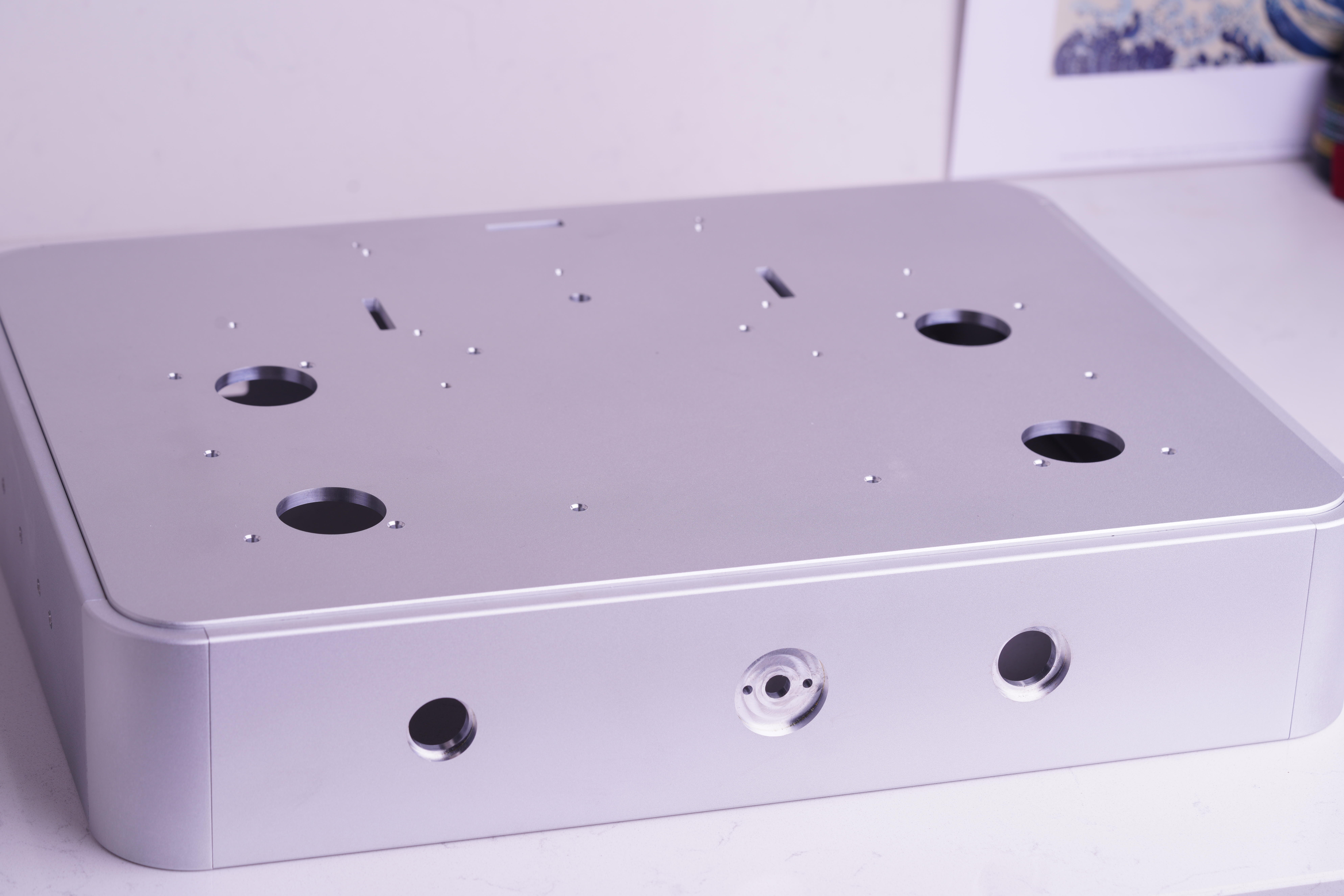
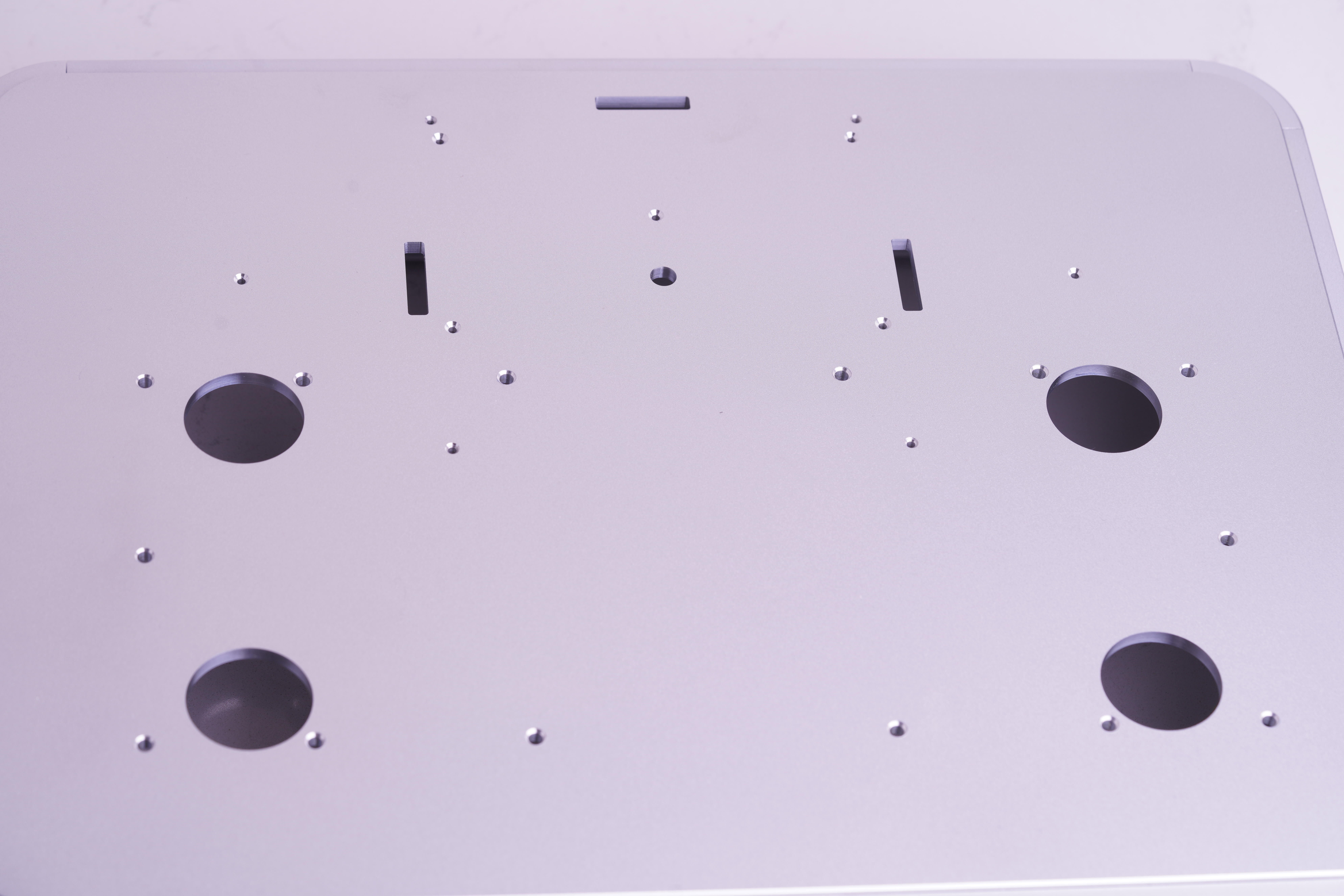
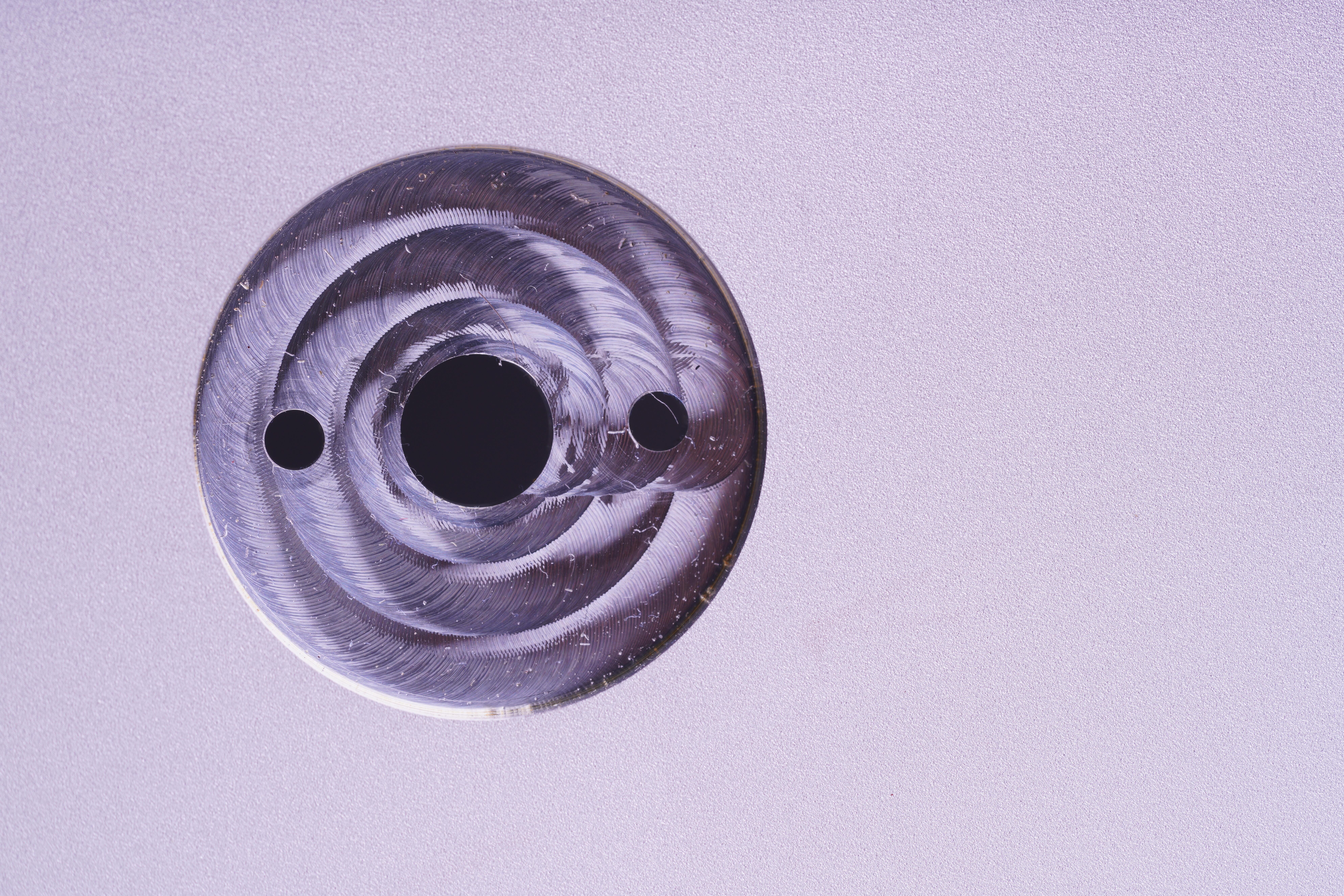
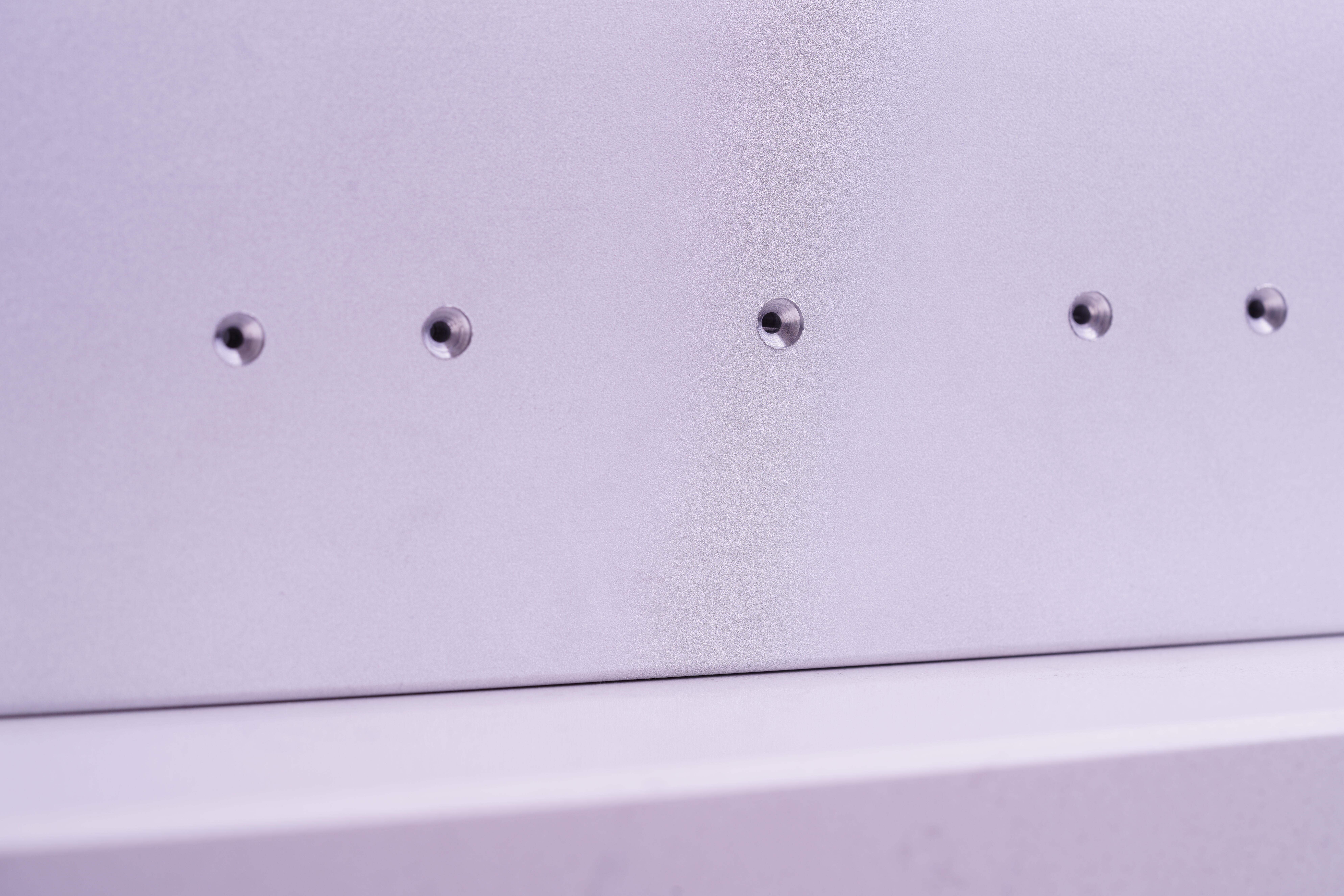
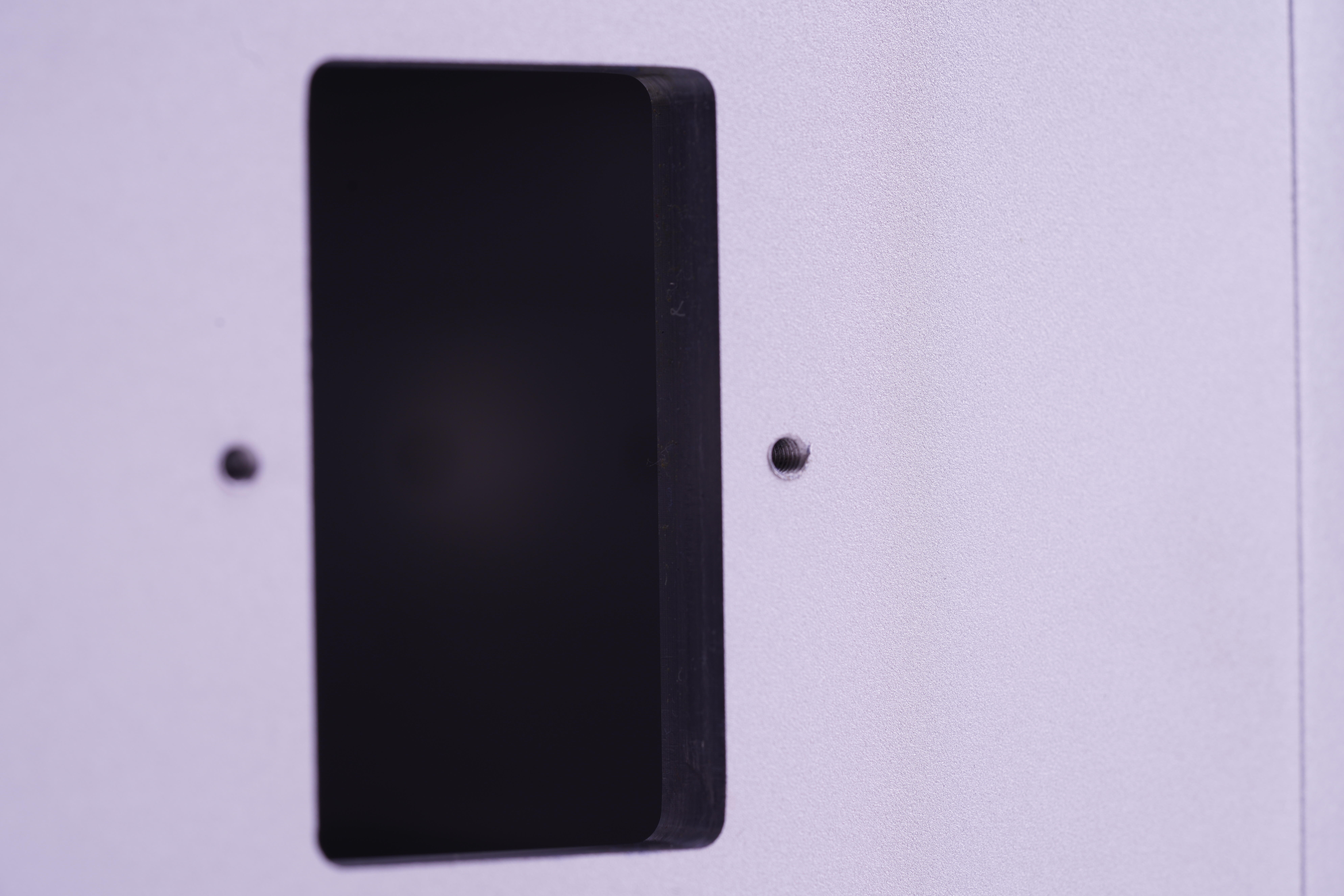
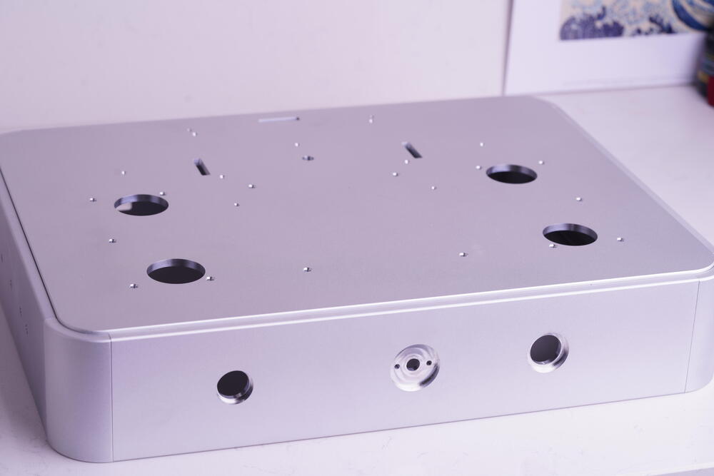
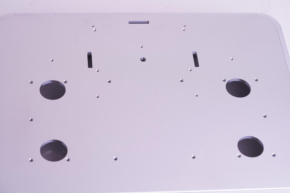
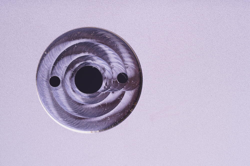
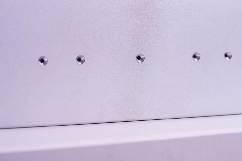
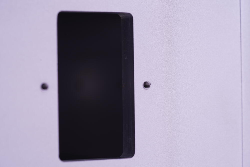
Okay, two months since my last post -time to dive deeper into the enclosure. I spent the past two weeks designing, ordering materials, and milling all the necessary holes. After breaking two milling bits in the process, here’s the result! The upper panel features over 30 screw holes for the amp boards and power supply. The transformer is planned to be mounted in the center using an M8 bolt, along with an isolated cover. Most of the screw holes are chamfered (using a chamfer milling bit). The square holes are designed for the transformer wires to pass through. The tapping work was manually done. Here’s the hole for the volume pot. The pot can be installed upside down to provide more clearance. I used an end milling bit, which resulted in this textured finish. The side panel will house the 10M90S without heatsinks. The plan is to transfer the heat directly to the enclosure. The enclosure dimensions are 430 x 80 x 330mm with an 8mm thickness. Two XLR input holes. Hole for the EMI AC inlet socket. I’ve realized that I might need a more professional CNC milling machine, but my garage just doesn’t have the space for such a large machine. Milling is really fun and incredibly satisfying.😆 How about going even further next, let`s say a fully CNC block enclosure (I am planning it right now).

-
Okay. After multiple checks for the occasional humming issues for a week. I finally learned the lessons. Separate each channel into individual space connectors. The two EL34 heater cables can`t go through the same connector(or be too close). The two 460V rails may have interference with each other, but I don`t have the knowledge to explain it.
-
-
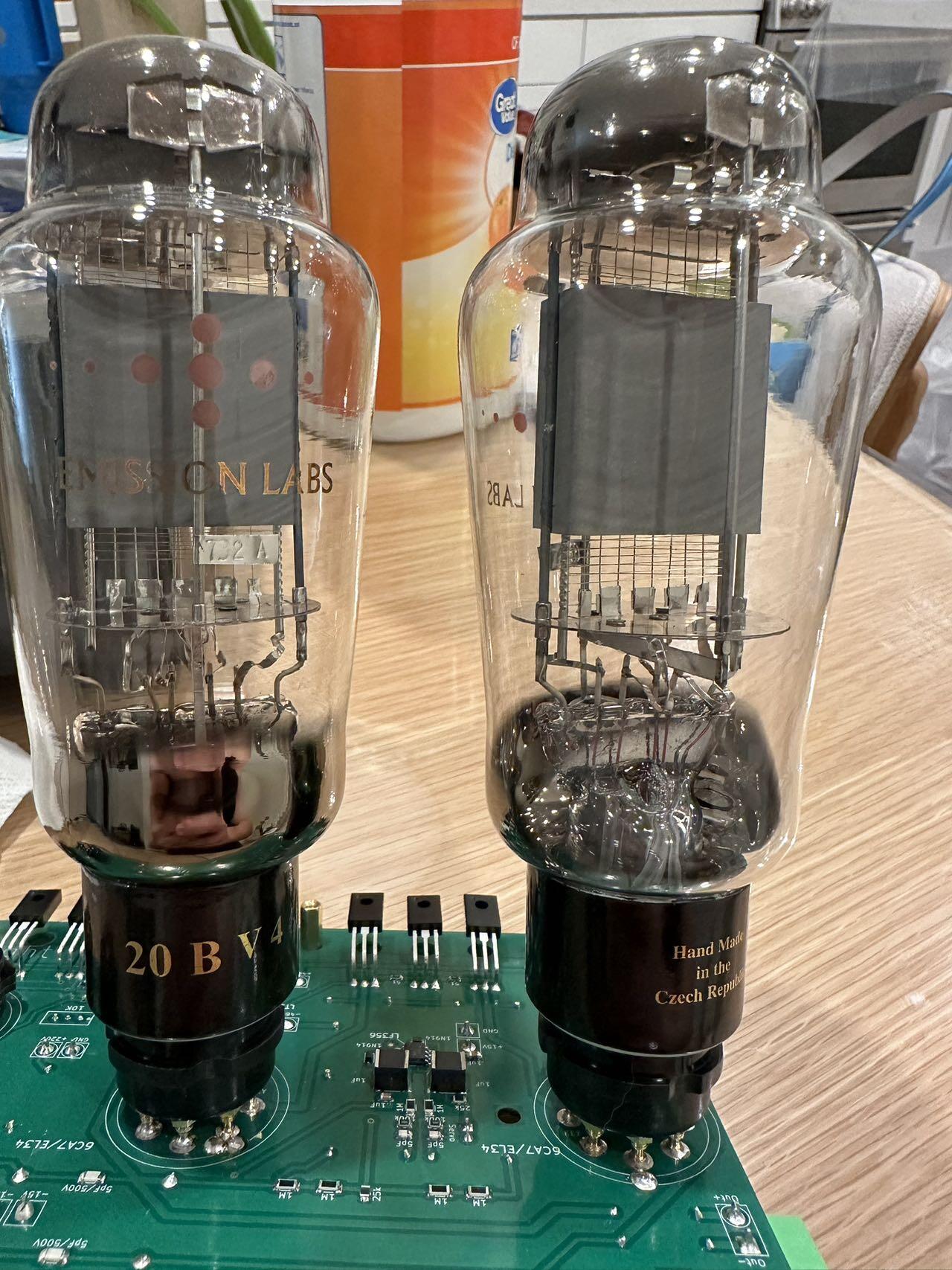
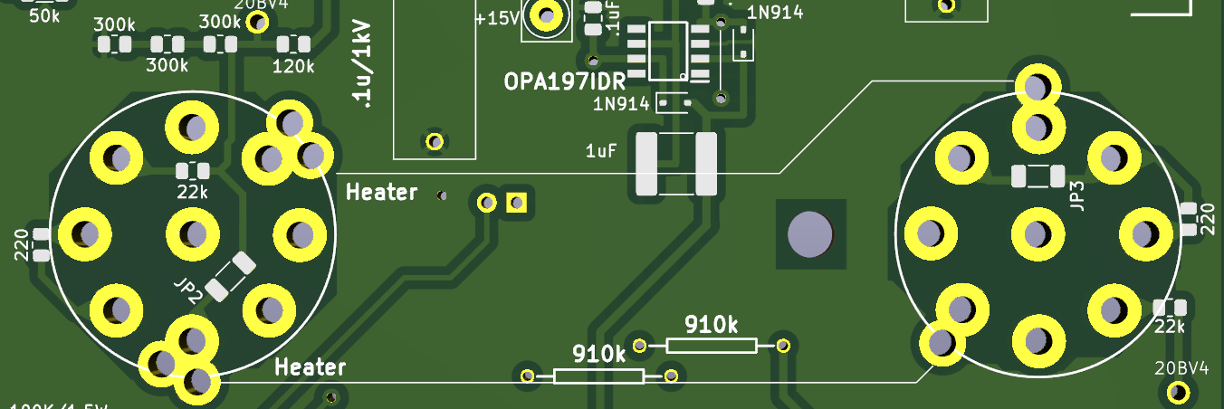
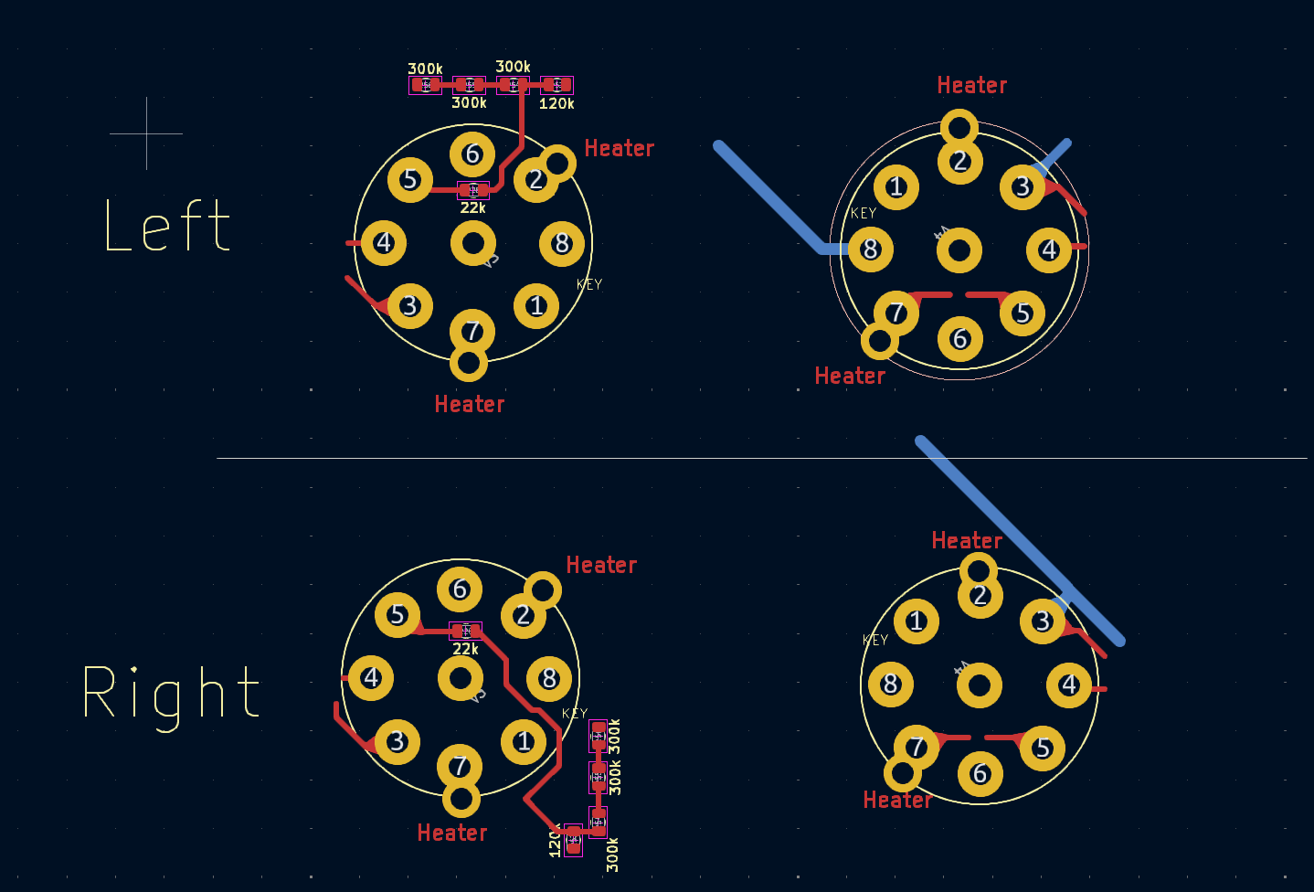
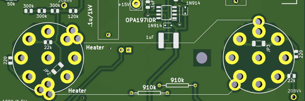
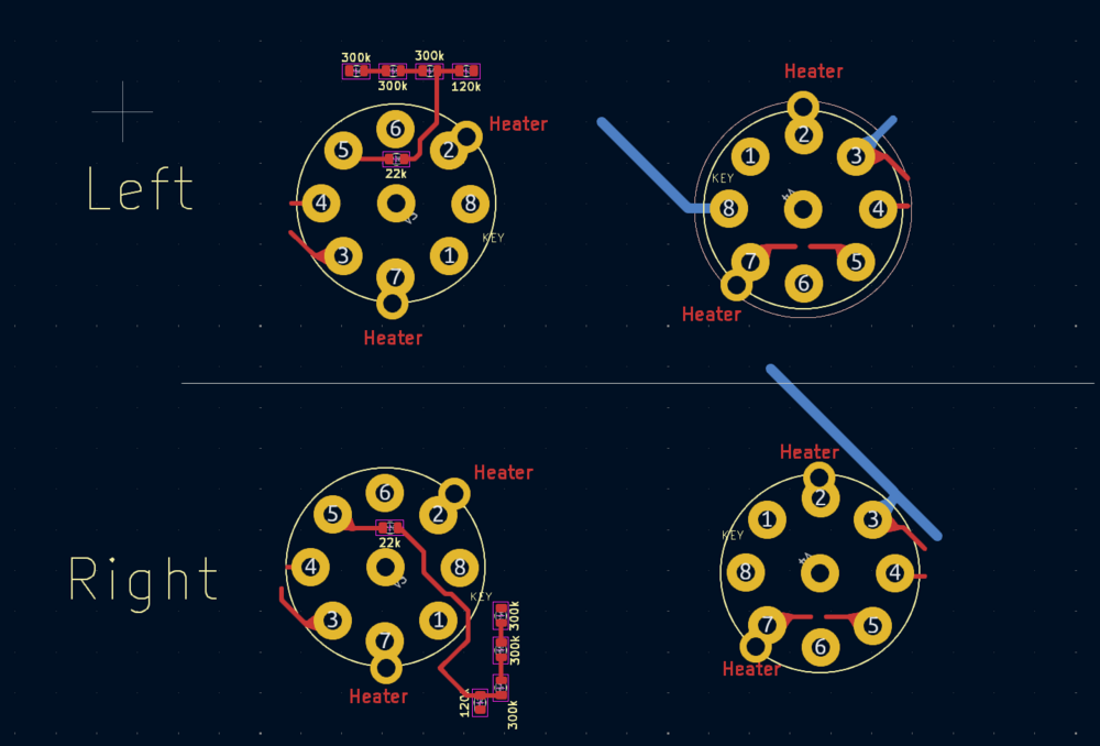
Done. Credit to JoaMat. Instruction again for 20B-V4 each channel: 1. Remove JP1~JP3(JP1 on the back which is connect Pin 1 & 3). 2. Remove two 220 ohms resistors. 3. Remove the right-hand side 22k ohms resistor. 4. Wiring the two pads which are marked as 20BV4. 5. Separate heater power supply. Based on layout ver.23. Hope this instruction can help someone keep investing in their mini T2.😊
-
Here is the draft based on your description. Regarding No.5, Should I pull the right-hand side(picture below) Pin5(G1) also to the resistor string between 120K and 300K resistors? Also Could you double check if there is anything I missed? Ignored the blue traces that go to KSC2690A and O-. I will be working on the new layout after making sure it is correct. You know what? You are at another level of speed. I was thinking about your description and gonna say the zero jumper is the solution and you did it!
-
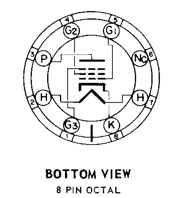
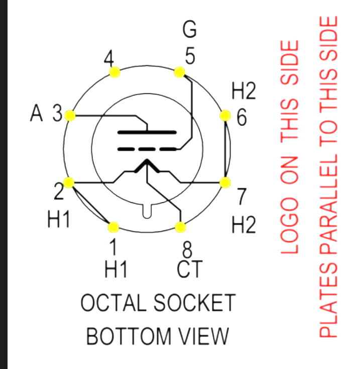
The size is impressively small. What is the heat generation of it? Excuse me for one more question, JoaMat. Here are the socket views of 6CA7 and 20B-V4. To convert the 6CA7 to 20B-V4: 1. Pins 1 & 2, Pins 6 & 7 will be supplied by 5VDC instead of 6.3VAC. 2. Each 20B-V4 needs to be powered by separate supplies. 3. The Pin 8 which is CT on 20B-V4 remains the same since it's the Cathode on DHT. 4. Disconnect Pin 4 Please correct me if I'm wrong. Don`t really want to massive and fry those expensive tubes. Don`t know what to do with Pin1(G3). And there is a 220Ohms resistor between Pin 3&4 and 22KOhms between Pin 2&5, Do I need to change it?
-
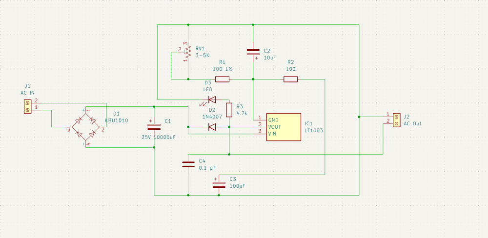
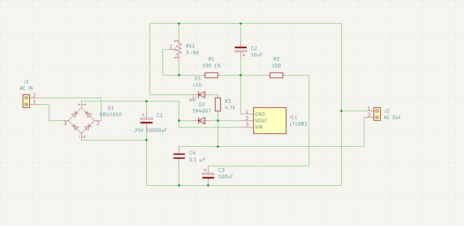
Not original from me. I found it on Alibaba and made some changes to it. Here is the schematic I drew it under 10 mins. Well... not perfect but readable. The size is 96mm*35mm. Still can shrink it down by removing the heatsink and attaching it to the chassis. What is the size of your DC-DC converter? And your pics remind me I have a bunch of 20B-V4 sitting in my garage for yrs. How do you convert the circuit to adapt 20B-V4?😳 AC Out should be DC Out.