ibuski
-
Posts
29 -
Joined
-
Last visited
ibuski's Achievements
Advanced Member (3/6)
8
Reputation
-
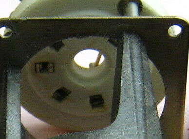
Hi Simmconn, Thank you for your suggestion about the sockets for GU50/FU50. Problem of decent sockets for them is, their price is usually higher than the tube itself. And when I see NOS metal sockets, their connectors don't look good as yours, see picture for example. Is that type of better quality sockets available in China local market only? I made research on Internet incl. Aliexpress but haven't found that type. Yes, the risk of putting pins into the gap between ceramic folder and metal connector was mentioned, sometimes even possible to damage the tube. We have to be careful to use those loose holding sockets....

-
WoW it ended up with 1.5 million Japanese Yen!! Original T2's bid price was extreme in these decades, but this is....😵 I don't believe that old machine sounds better than modern DIY T2s, but probably for the buyer that's not theme. It's really rare item. Besides that, SR_Omega doesn't get too much attention, probably after recent top model of STAX Ear speaker became available, I mean models with number "9". One SR-Omega has been for sale with 880,000 JPY and another one sold with SRM-T1W costs only 750,000 (still active).
-
Wonderful!! I found that GU50/FU50 has been put on spotlight in these years in speaker amplifier world and sometimes called as poor man's 300B. Although its unique appearance and rare metal socket made many DIYer hesitate, its characteristics advantage is being recognized and Chinese cheap sockets are now available. I think you're the first to put them into E-stat amplifier and it's nice challenge considering the high voltage usage. Your way of try and improvement was quite interesting. Adjustment of Vg2 story was exciting. The resulted performance is impressive. I couldn't stop placing order for some GU50s on eBay as they are such cheap (20-30 EUR for brand new Quad incl. shipping) 🙂 Thank you very much for your sharing this great experiment with us.
-
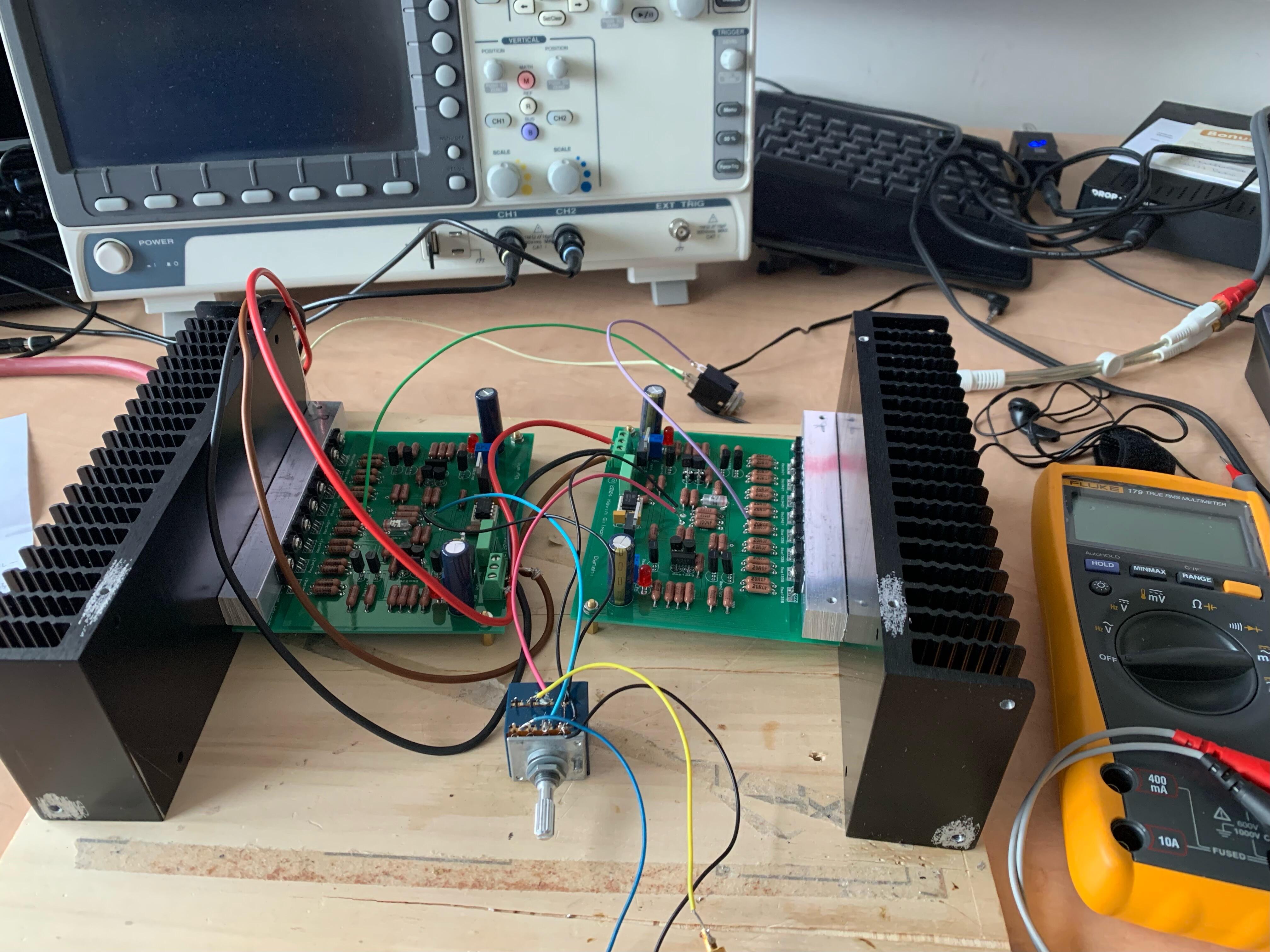
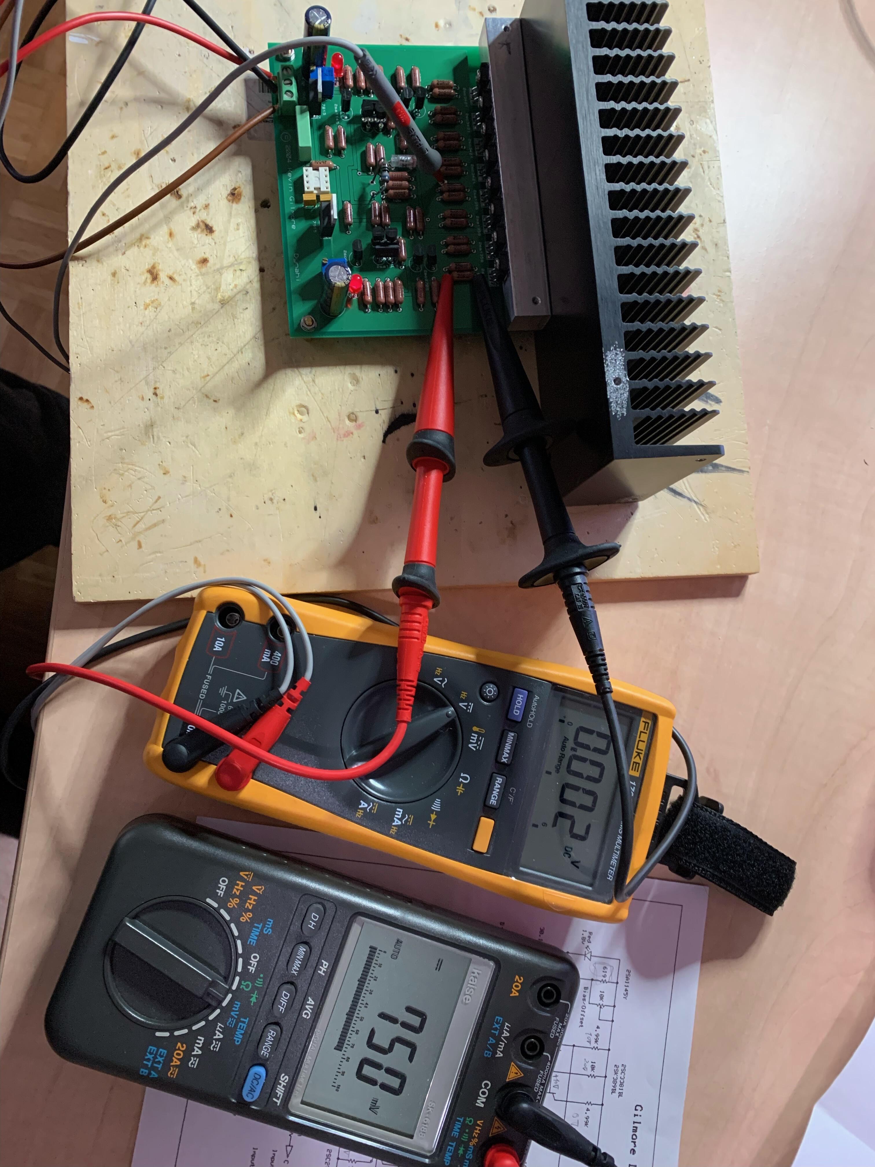
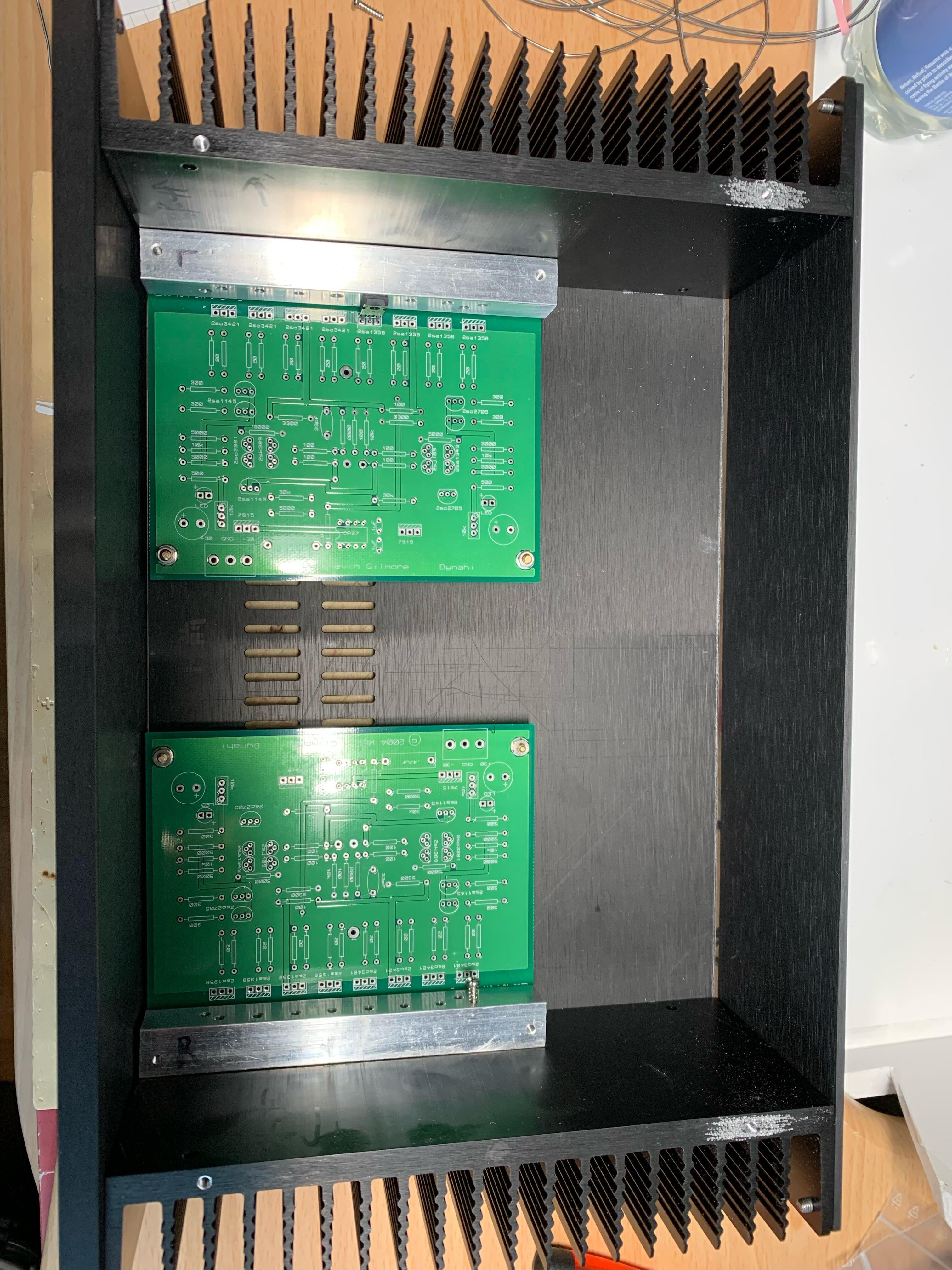
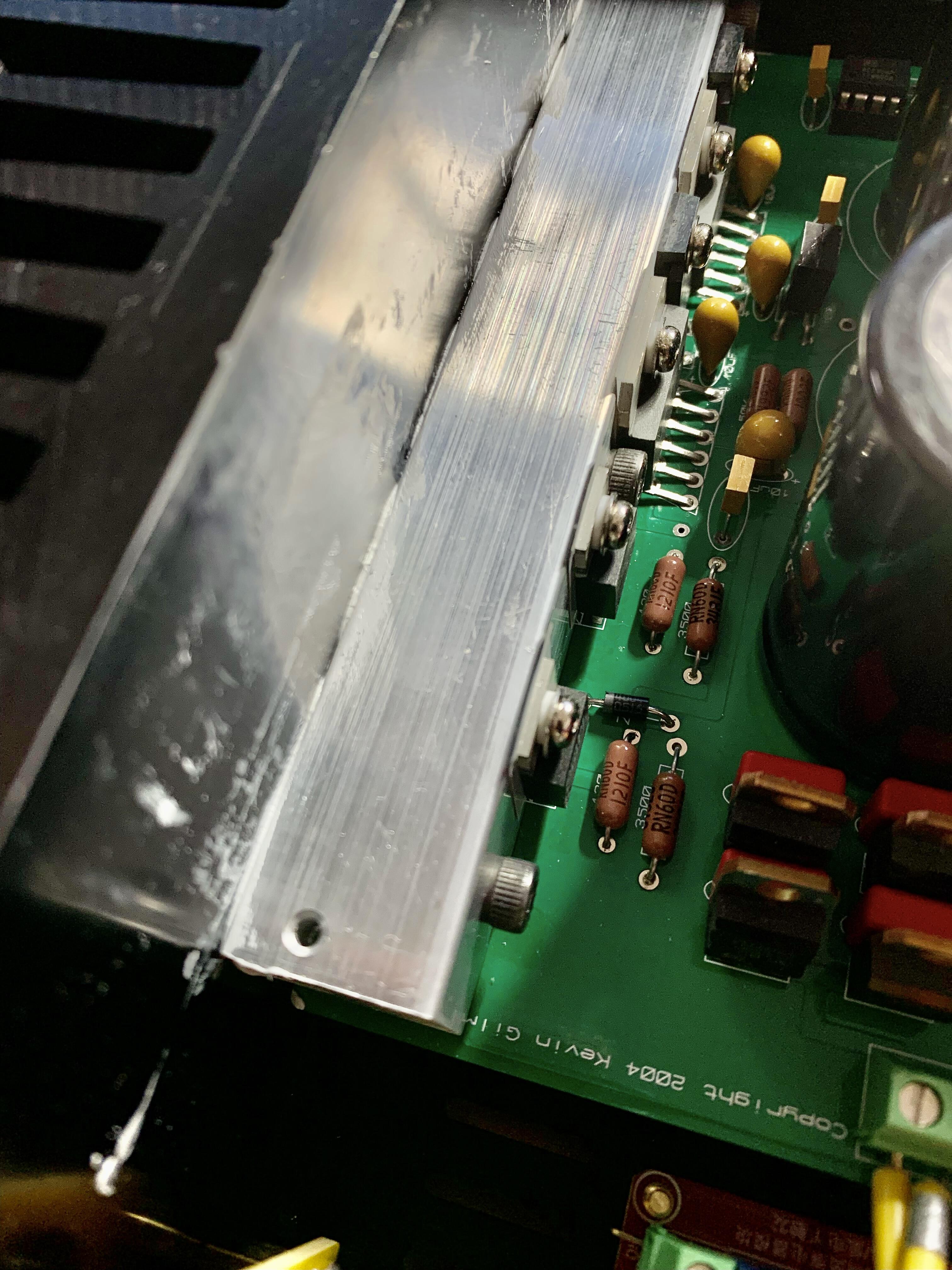
Metal works made some progress on my DYNAHI housing. You see original 2004 old PCBs. I could fix all thread holes position then was ready for soldering. I kept front and rear panel untouched and decided to start something electric. Adjustment of output transistors bias current and DC offset was done so-so OK. I realized that asymmetric heatsink location to the PCB wasn't good design when considering temperature balance between 2SA1358 and 2SC3421. While heating up, I had to continuously adjust DC offset before mounting OPamp. Hopefully DC servo works in real operation. I started checking the sound with cheapo earphones. Yes, it makes music so loud. I couldn't turn the volume pot more than 30 degree. It seems there is nothing critically wrong, so I switched to others. Grado requires 45 degree and ETHER2 demanded ca. 80 degree. I selected the gain ratio 7 with 1200 & 200 Ohm resisters, but it's still a bit too sensitive. Although I wrote not critical, a big problem is Hum. It's terrible with Chassis ground connected to PCB ground on the PS. When I lifted it, it's significantly decreased. Still it's barely audible at high volume position without music though. I'll work on this after putting everything in the housing. I wouldn't leave the PCB ground isolated from the Chassis ground.
-
Thank you for links. The first link product looks definitely for professional or semi-professional. I have to think if those $100 - $250 is compensated by saving $30 heatsinks. Probably I won't build more than 2-3 amplifiers with block heatsink in my rest of life 🙂 I learned why not many builders use square bar to mount Transistors, and will use L-angle next time. Then I can use bolt & nut instead of tapped holes. Accessing to the screw from PCB top is easy.... It was almost impossible to exchange LM338T on the square bar after mounting large condensers on PCB. I didn't think about any possibility of repair or trouble shooting.
-
Thanks for suggestion. You mean a tapping jig like this? https://biggatortools.blog/tag/tapping-jig/ or like this? https://www.pinterest.de/pin/563442603351835015/ I've been using this old tap handle without a jig and haven't had any problem on soft aluminum holes. I could be just lucky. I know, it's sooo troublesome when the tap is broken in the hole. Key point is to hold the tap accurately perpendicular to the block surface in the first some turns. So far it worked. I may fail it in next time.... Don't know how much that jig costs.
-
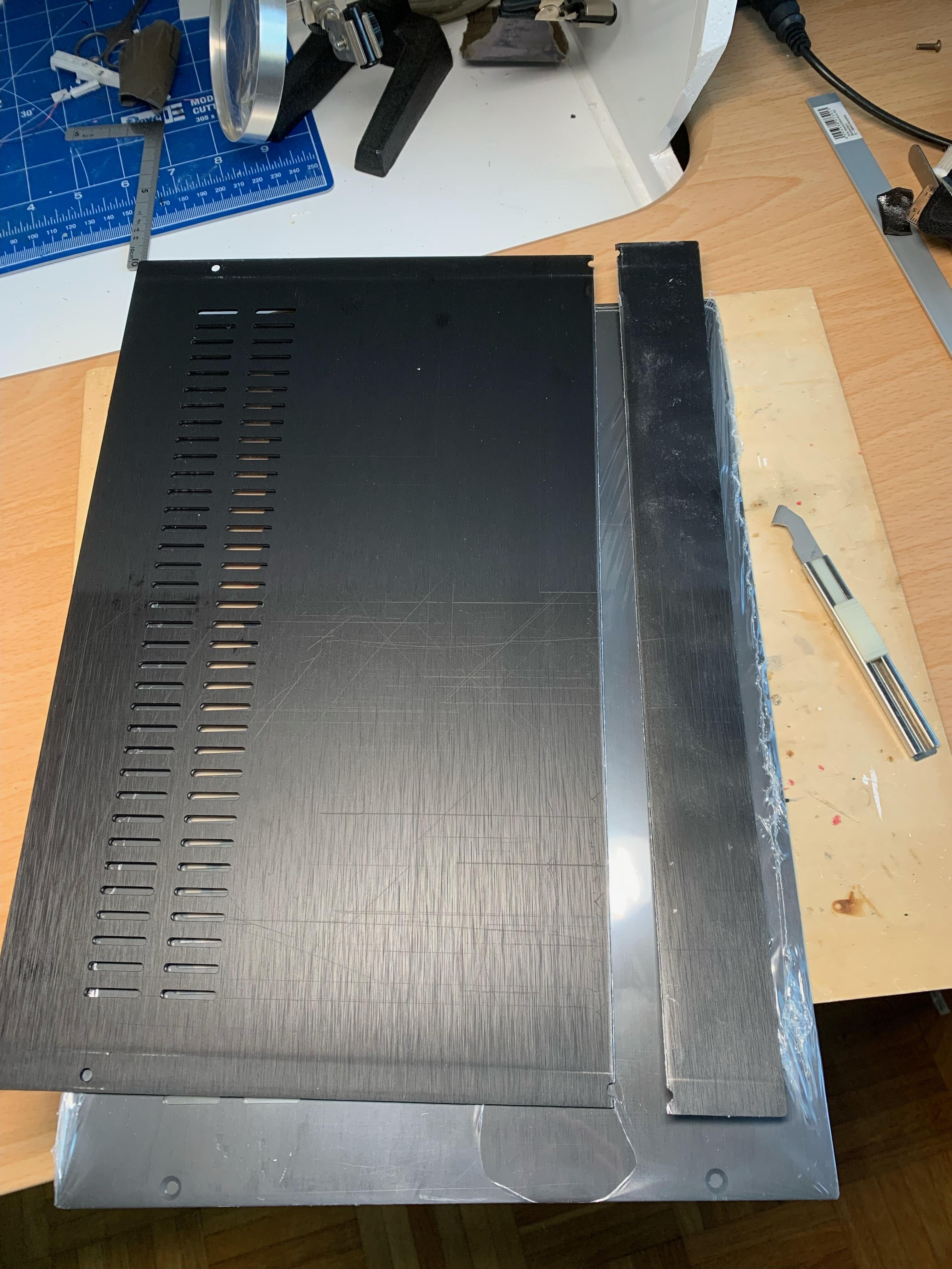
Metal work I meant.... Cutting 230 mm depth aluminum panel (t=3mm) to 200 mm, to fit to tight space on my desk. Started Cutting with a small tool on the photo. I could achieve only ca. 0.5 mm depth of scratches on both sides. Then I clamped that on my wood working bench, and hit hard with a hammer. It worked. I could make straight, so-so sharp section. Some burrs can be removed with a file. I need to paint the shining edge black. It shouldn't be so visible as it's on rear side. This should fit to 200mm length heatsinks with Hifi2000 front and rear panels. Then many drilling, tapping, chamfering,.... Oh I shouldn't forget to peel anodized black coating to have whole chassis plates conductive.
-
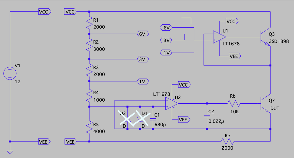
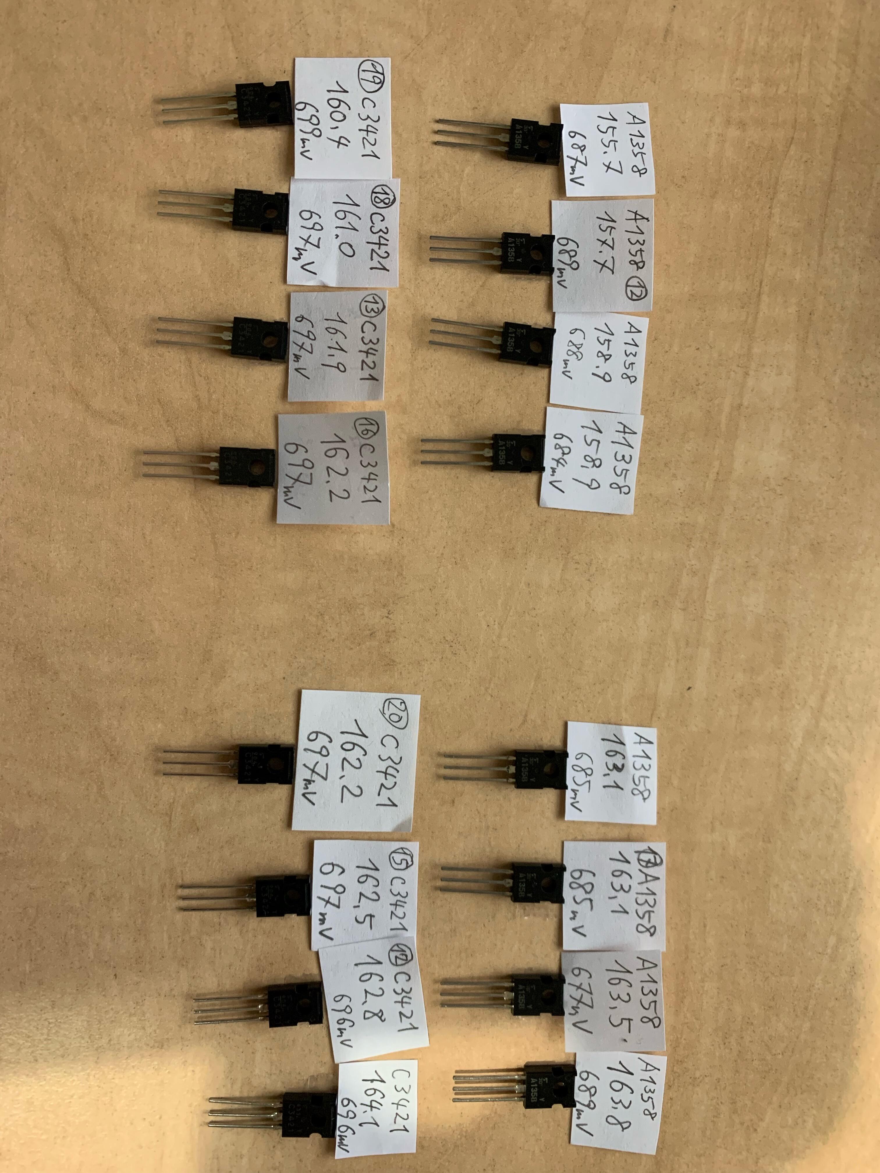
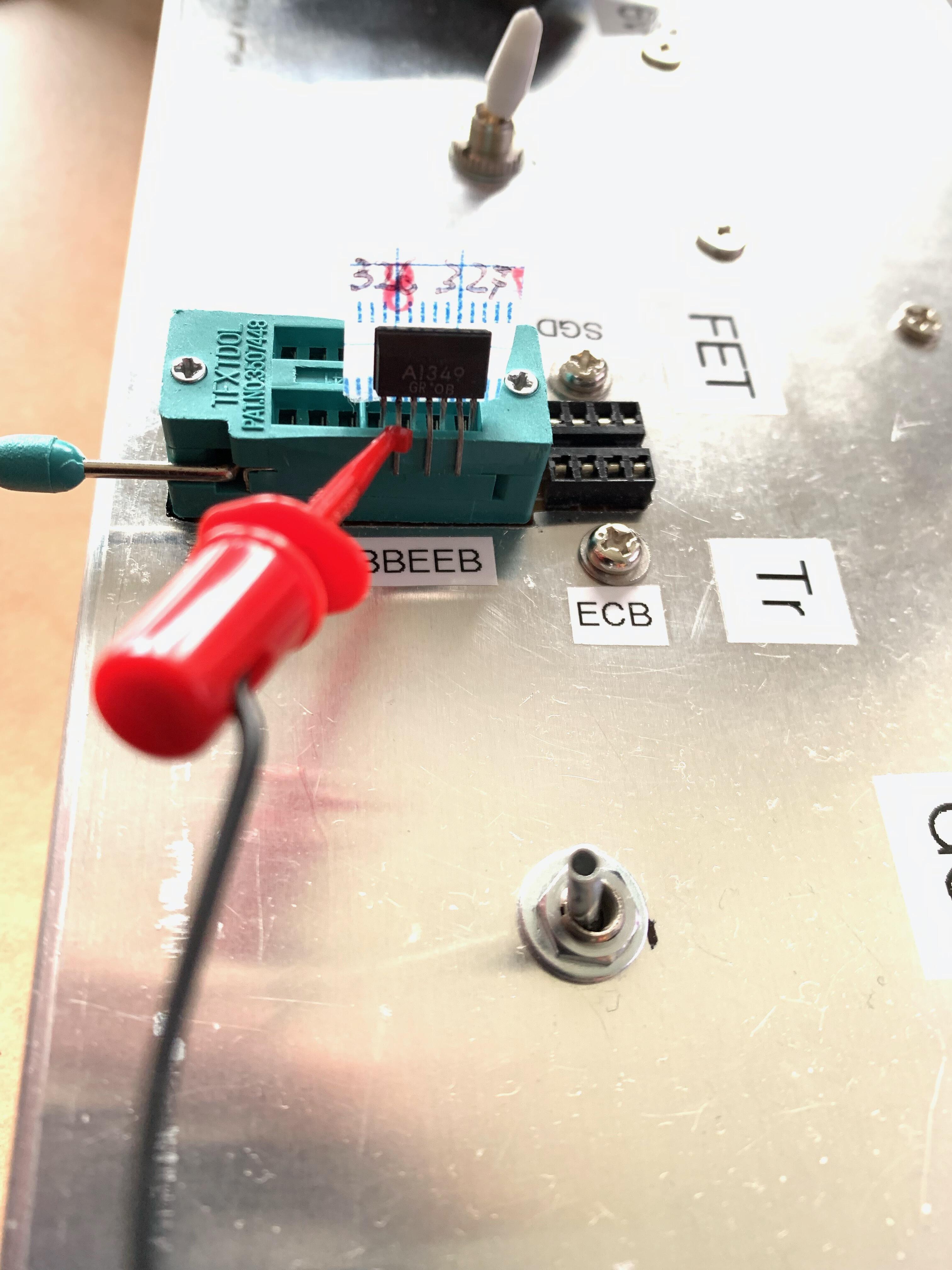
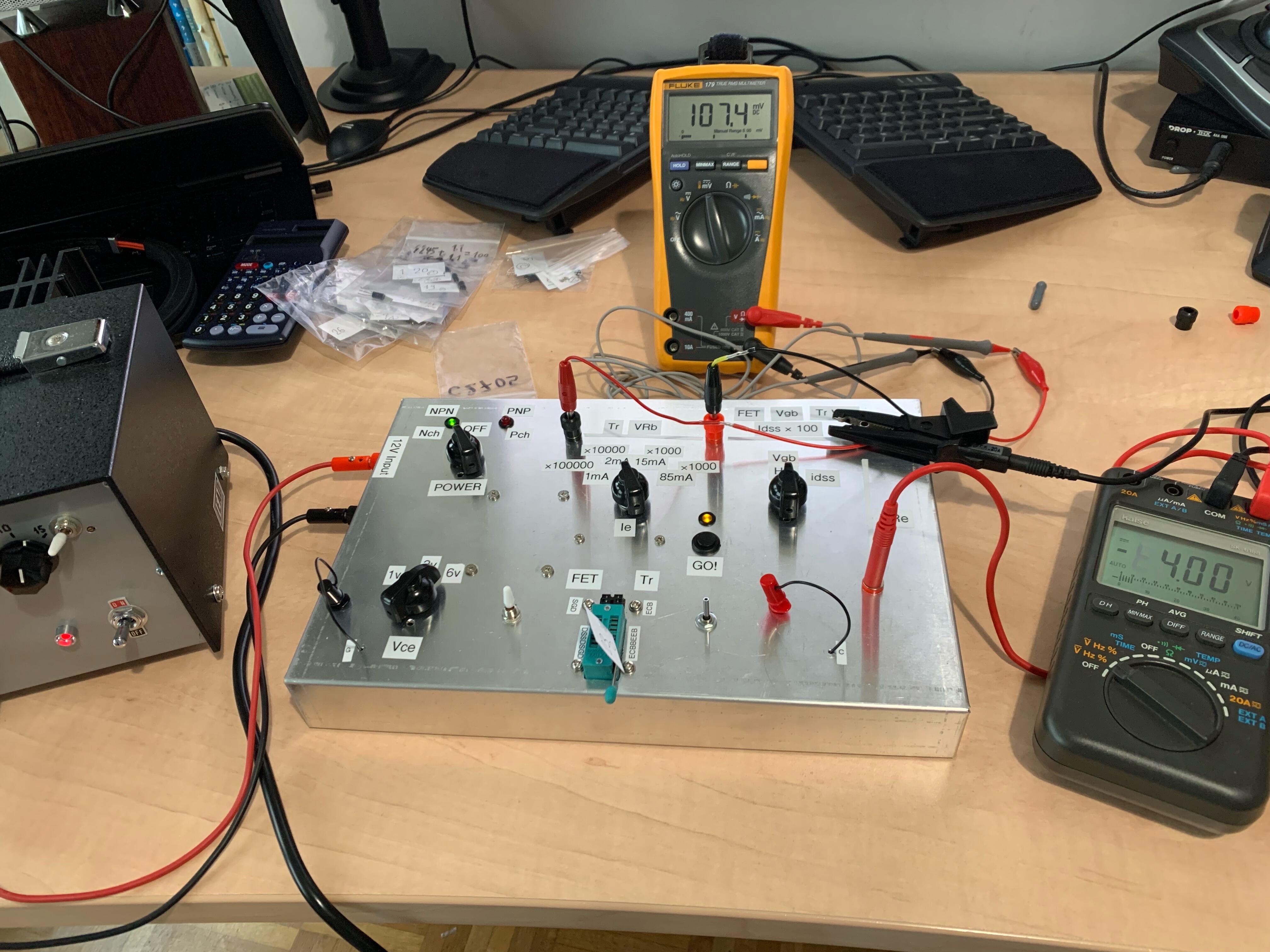
To build Dynahi, I need to match the Transistors, so I made a Hfe & Vbe tester. I made up it as a chimera of several online information about Tr measurement device. I posted that schematic to DIYAudio since it worked well in LTSpice, expecting somebody can review it. However later I found that I need to take two protection Diodes out to make it work in reality. Also the constant voltage circuit taking DUT in the OPamp's feedback loop wasn't as perfect as simulation. LT1078 was the most accurate OPamp I had, and achieved 0 error at Ic: 85mA mode, but it left 60mV error to the 4.00V reference VRe with low current. OPA2134 was perfect at low current, but generated more than 100mV error at 85mA of Ic. Eventually I used old uA4558TC that maintained average error 10mV to 4V reference over the range from 1mA to 85mA of Ic. Against all effort of parts selection, I ended up manually adjusting VRe to 4.000V on my power supply for each single Tr/FET. I could find good matched quad for A1358/C3421 and other Tr, but had difficulty for J109/K389. Then I bought matched J74/K170 on eBay, but one pair wasn't matched as I wrote in HC before. Finally I could find good matched pair of them from extra 10 pcs. of purchase in Yahoo auction in Japan. Reliable seller's J74/K170 even non-matched weren't cheap though. Now I'm ready to populate them to PCB? Before doing so, I need to prepare heatsinks to fix A1358/C3421. And the heatsink requires threaded holes to be mounted to the housing. The positioning of the holes requires fixing all aluminum plates on the chassis.
-
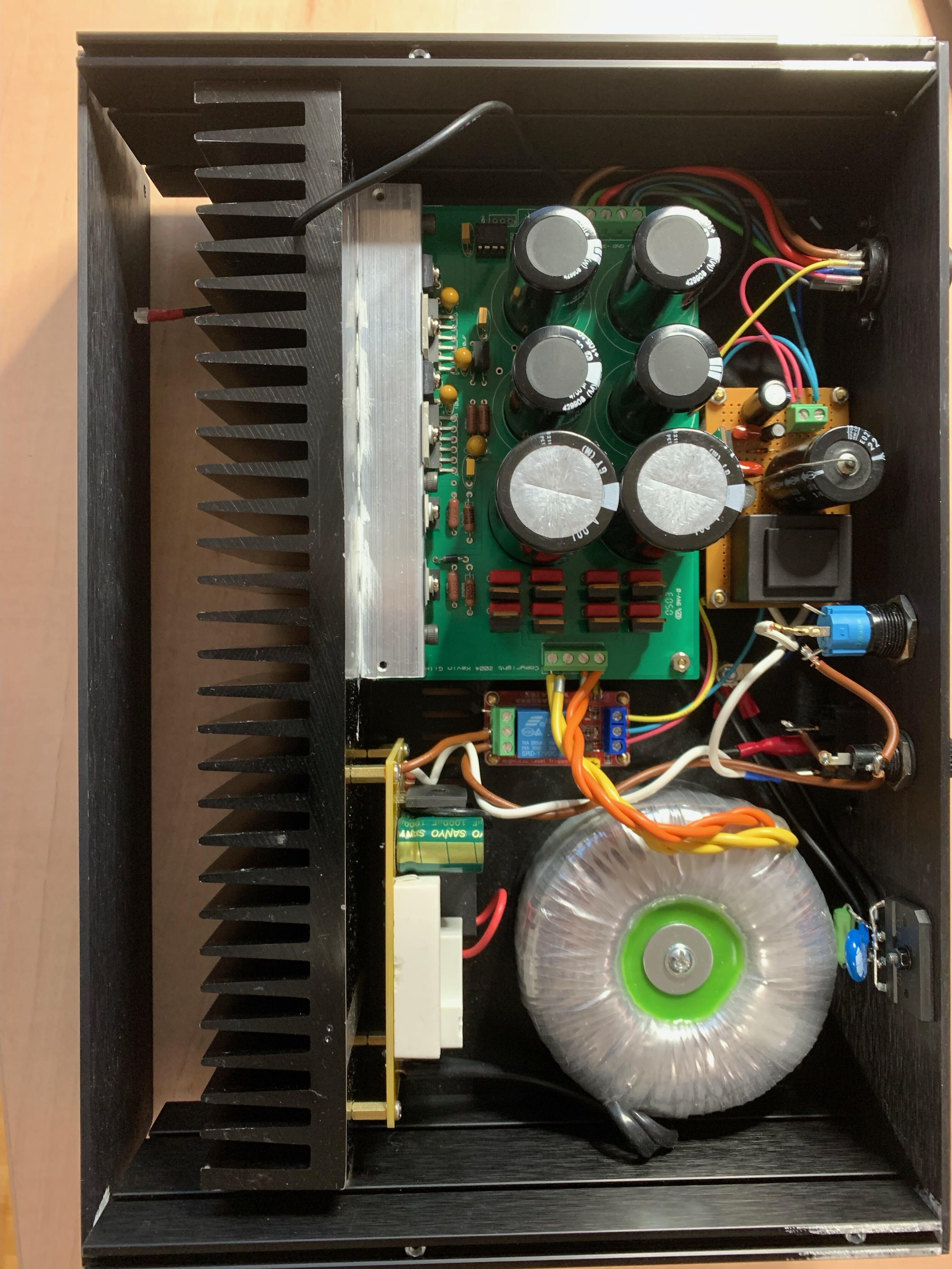
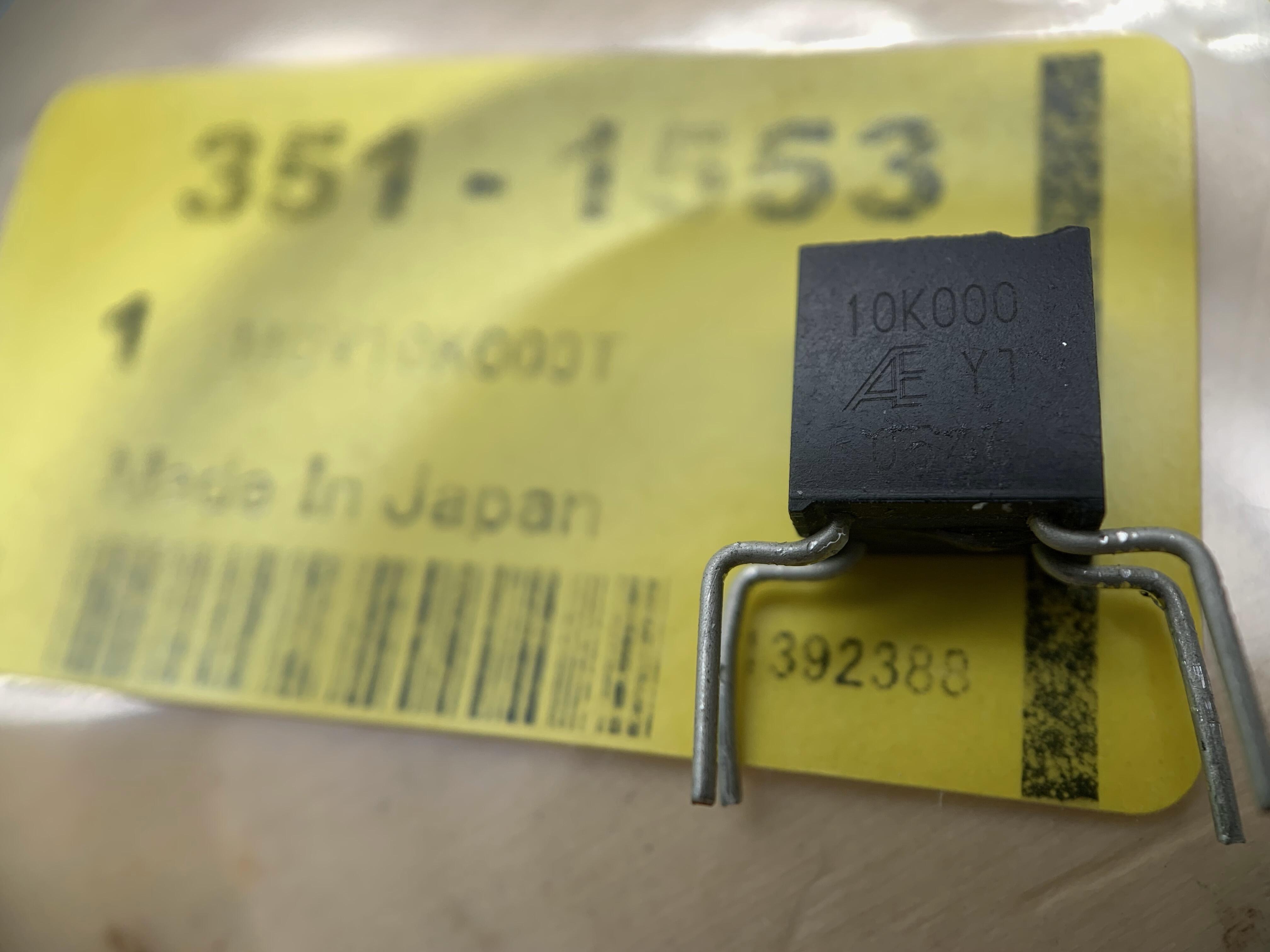
Almost completed original Dynahi PS. It was supposed to be my project in the Christmas holidays, but the short circuited one Diode leg pattern to the Ground destroyed some semiconductors. It worked as a voltage doubler surprisingly and the first stage DC voltage came close to 100 V (!) on the negative channel (That's why I put fatty 100V 4700uF Nichicon there to continue trouble shooting without worrying puncture of the condensers.) It took more than a month to solve the mystery why it doubled the voltage. Now it works fine. Thermally connected 10K Ohm Alpha Electronics precision registers assure perfect match of positive and negative supply voltage. Housing is a popular Hifi 2000 Galaxy, but heavily modified. 230 mm depth chassis is combined with 170 mm depth top/bottom plates, and a large heatsink (bought as secondhand so cheap) is attached to the front behind the face plate. Anyway it will be located below my desk and I don't care much about the appearance though. Next is Dynahi amplifier... Lot's of metal work are waiting for me. One thing I learned in this trouble, LM338T isn't as fragile as thought. It was still alive even after more than 50 V of voltage gap from input to output was given. However "alive" didn't mean it worked flawlessly. After that, Vref of damaged LM338 became ca. 1.6 V instead of 1.25 V. It's still usable when taking that Vref into account. I confirmed the output voltage is stable, only shifted. I'll use it for non-critical voltage supply purpose.
-
Farnell now has some stock of IXCY 10m90s. Note not IXCP, they are SMD. https://export.farnell.com/ixys-semiconductor/ixcy10m90s/current-regulator-900v-0-009a/dp/3438367 They have DN2540N5-G of course back order, but their expected delivery date is April, earlier than Mouser's "November"? Is this reliable???
-
Megatron Electrostatic Headphone Amplifier
ibuski replied to kevin gilmore's topic in Do It Yourself
Oh really? Then ultimate amplifier would be combination of Tube diode CRC driving GRHV + T2 + Megatron style CCS ? full of tubes... -
Megatron Electrostatic Headphone Amplifier
ibuski replied to kevin gilmore's topic in Do It Yourself
Thank you Kevin, I haven't thought about transformers. Tube diode wasn't in my focus. For any design of eStat amp (KGSSHV, BH, MT, GG, etc..), I think most of people now select GRHV type PSU as it's known as the best performance. Or is there special synergy when tube PSU is paired with full tube amplifier like Megatron? From appearance point, yes... -
Megatron Electrostatic Headphone Amplifier
ibuski replied to kevin gilmore's topic in Do It Yourself
Kevin, I remember your old post telling that the best design CCS is a high voltage tube with a cathode resistor, i.e. Megatron. It should be better theoretically than any cascoded FET or T2 style BJT CCS, I read. Is that still true? I'm tempted to think Megatron as my next project because it doesn't require many rare semiconductors and the PCB is available from Aliexpress while I haven't seen other Gilmore design PCB on sell. Finding reasonable Tubes shouldn't be problem and anyway I have some already. The amount of heat from 8 EL34 makes me a bit nervous though. BTW following above statement about CCS comparison, putting Megatron's CCS into T2 seems to be the ultimate amplifier, but I haven't seen anybody do so. just because it's too hot? -
Hundreds of 2SC3675? I'm drooling! Have never found such huge stock of "real" C3675 even in Japan. We know one shop shows hundreds of stock, but there is rumor they are not really....healthy. Original T2 requires 28 pcs. of C3675, right? How many T2s are you building? I understand that the KSC5026 takes current through KSA1156. When comparing three Tr, C3675's Ic looks low. KSA1156: Ic=0.5A, KSC5026: Vceo=800V, Ic=1.5A, 2SC3675: Vceo=900V, Ic=0.1A However there is 50k Ohm resister, thus the current is limited to 500 V/ 50k Ohm = 10mA for two Transistors, isn't it? I see no issue to use C3675. On initial GRHV design, there were STN0214.
-
Thank you Jamesmking for your detailed explanation and lot of information with many links to the valuable videos. That's exactly one great post and should be pinned to the top of thread for others, too. I have to take time to read/view them. One point about the signal generator. No, I don't have signal generator. I think I can start using PC software audio signal generator. Response to square wave should provide enough (or some?) information about high frequency behavior of the DIY amplifier, right? I also confirmed that cheap AWG (...6600, typically) are good enough and costs less than 100 EUR. So I won't consider paying extra 200 EUR for the additional AWG feature of Oscilloscope. Regarding DMM, it sounds that Brymen is specialized for E-stat amplifier builders, hearing its high voltage robustness up to kVs.... I had bought DMM last year, and don't know how robust it is for kV in resistance mode.