MASantos
-
Posts
592 -
Joined
-
Last visited
MASantos's Achievements
Limited Edition Bronze Participant (4/6)
96
Reputation
-

and now for something completely different part 3
MASantos replied to kevin gilmore's topic in Do It Yourself
I guess it would need extra spacing between the bcp and heatsink to acomodate the relays. Looks very nice, if you end up ordering boards for a finalized version, could I bother you with a set? I have a GRLV configured at 24V which could be put to work. I guess one of those mini dissipante cases from modushop should be a nice fit for this. -
and now for something completely different part 3
MASantos replied to kevin gilmore's topic in Do It Yourself
The dual op445 appears to have the best behaviour indeed. I'll keep following your progress -
and now for something completely different part 3
MASantos replied to kevin gilmore's topic in Do It Yourself
Thanks! I'll take a look at it. Regarding the smd transistors and input jfets, what was your reasoning for these choices? -
and now for something completely different part 3
MASantos replied to kevin gilmore's topic in Do It Yourself
Reviving this thread a bit. DIY itch is getting stronger. I would love to try and make a smd cfa3 with digital attenuator and protection circuit on 3 board layout. One board per heatink with the amplification circuit, and a central board with GRLV, input and output attenuator and protection circuit. Sort of what Justin did with his cfa3. Do you have a layout for your smd cfa3, and would you be willing to share it? I have played a bit with schematics editing and board layout, my idea would be to add the individual building blocks to the main board and try to make it fit a nice case such as the mini dissipante from modushop. -
How about an onboard psu for the attenuator? shouldn’t add too much real estate.
-
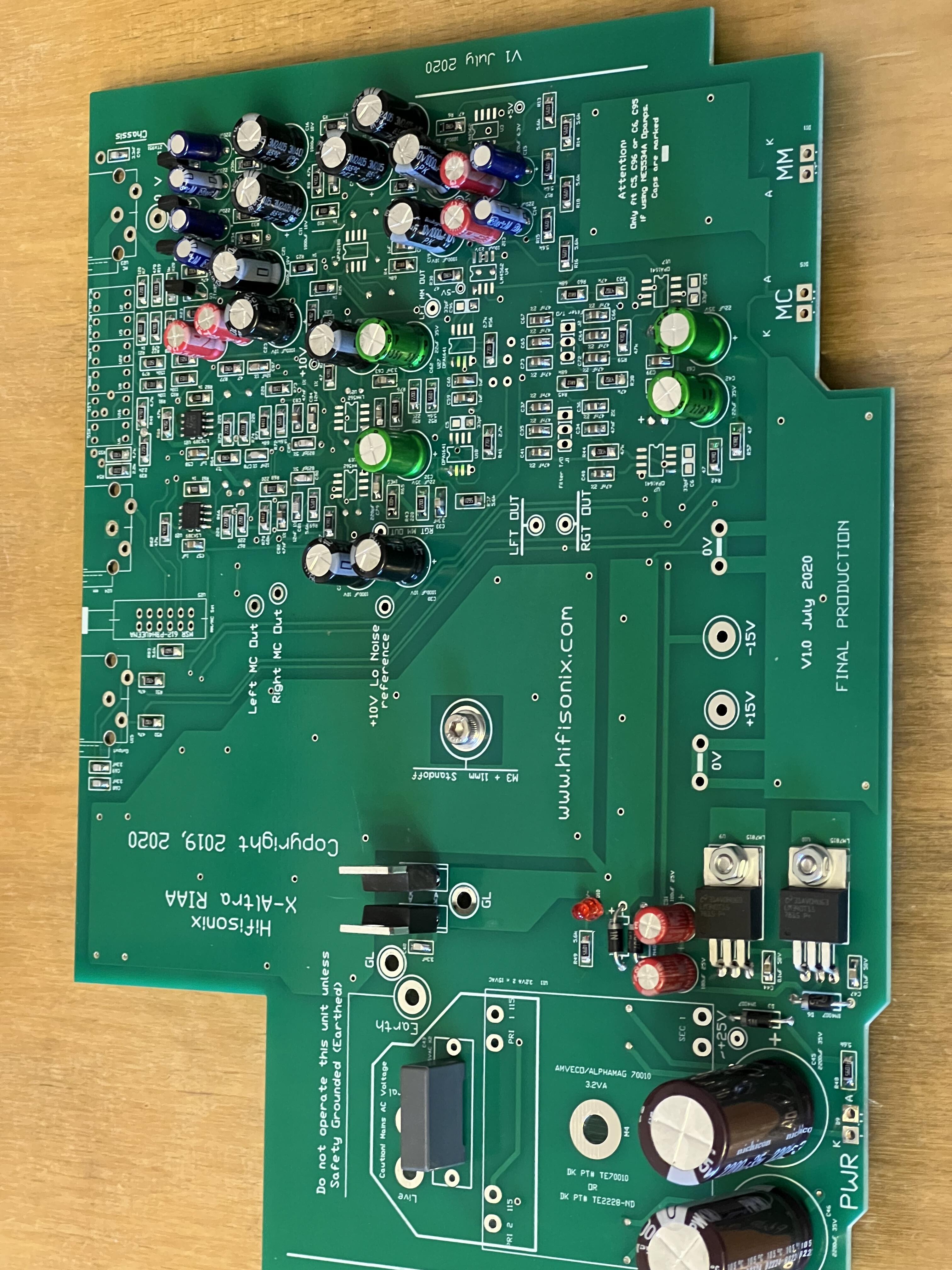
X-altra MM/MC phono stage. A project published on audioexpress a few years ago and a different design approach compared to my Simplistic phono designed by Salas over at diyaudio.com Will be fun to compare both.

-
dCS Lina: 30k USD Headphone/Network DAC/External Clock Stack
MASantos replied to nopants's topic in Headphone Amplification
I haven’t read through the tech specs of the amp, but is the volume actually controlled by the alps pot or is it done in the digital domain with the pot only acting as a controller? -
and now for something completely different part 3
MASantos replied to kevin gilmore's topic in Do It Yourself
Looks great!! Count me interested in a group buy! -
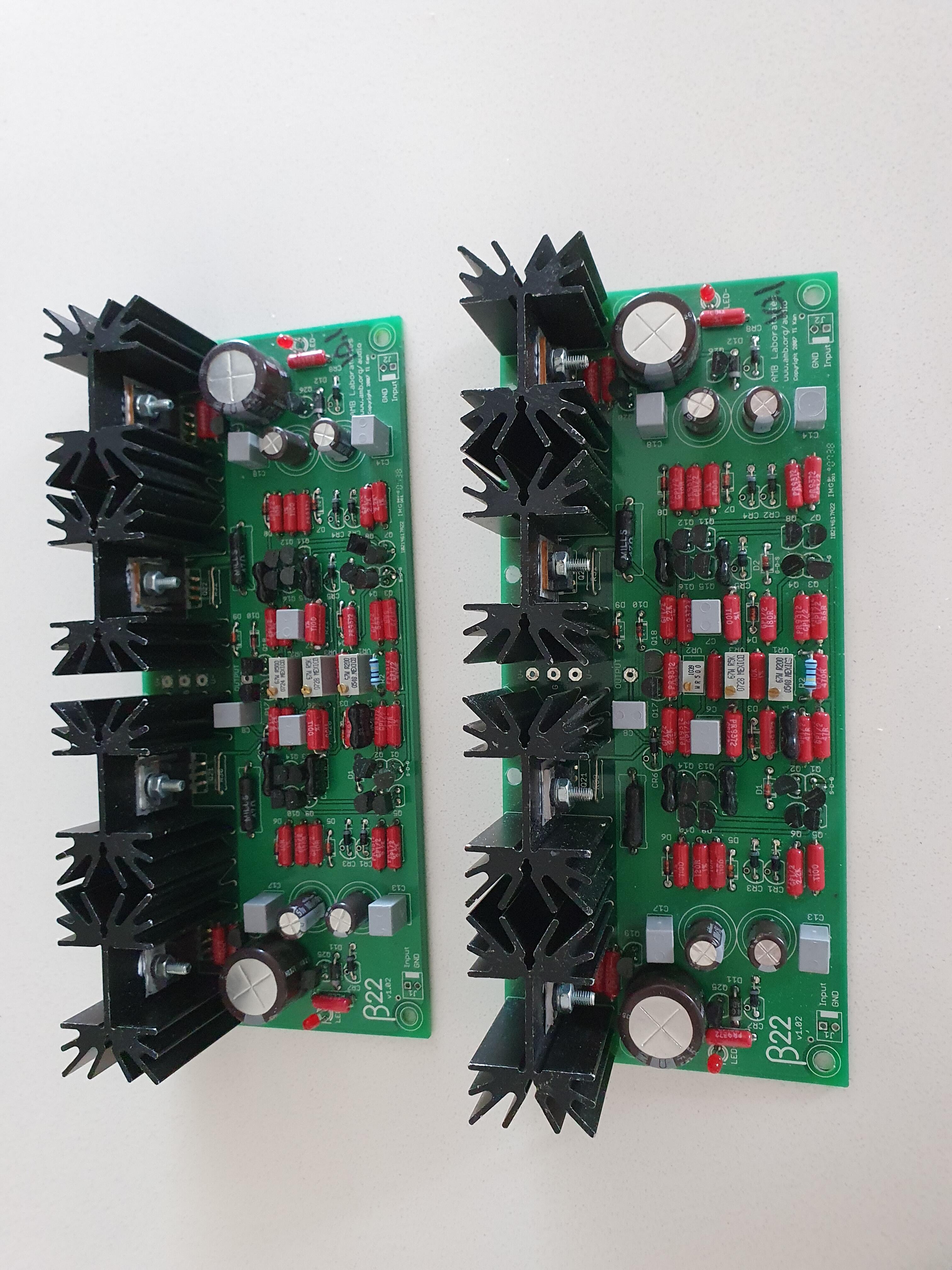
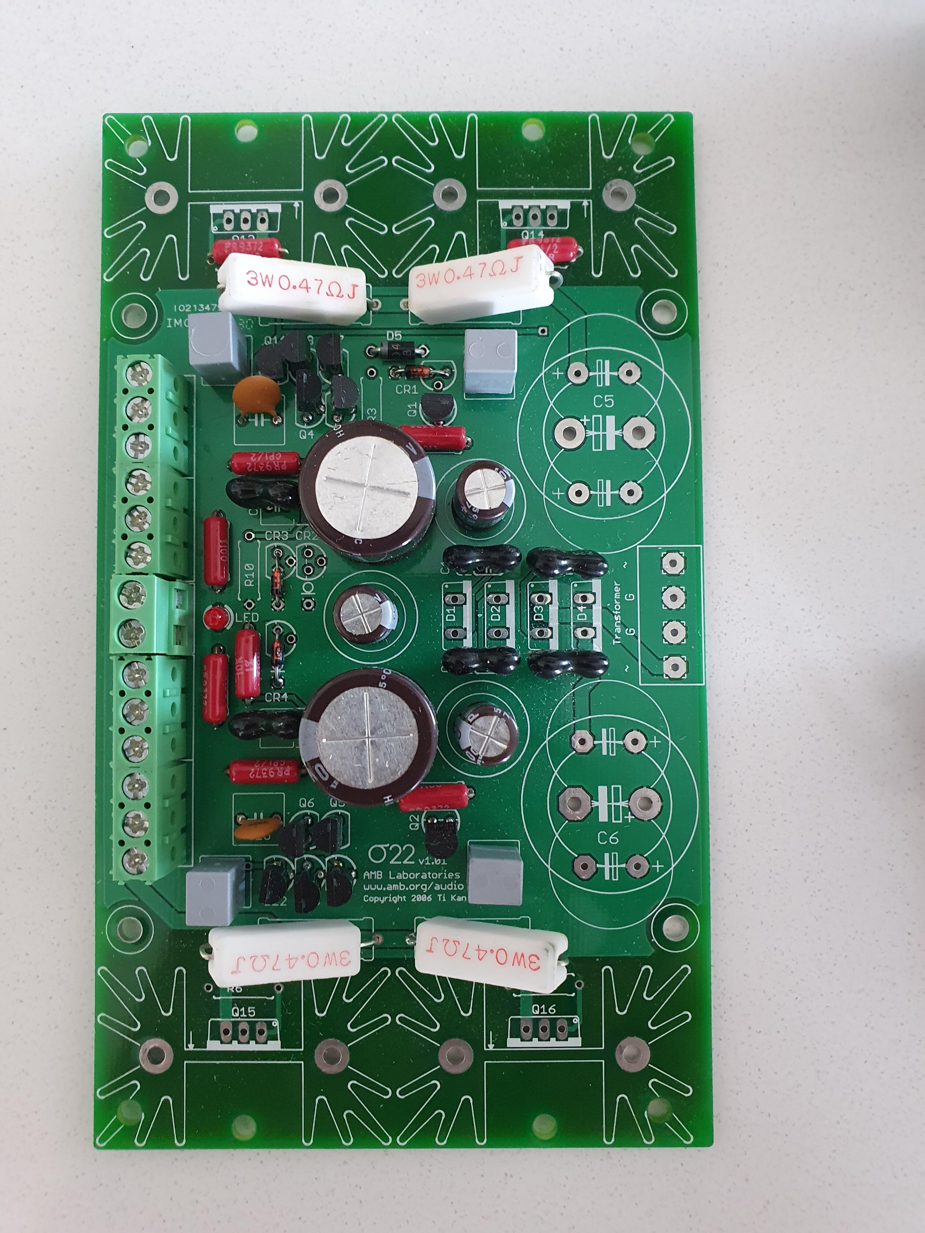
Got these b22 and o2 boards over at diyaudio for the price of the input jfets alone. Will have to review them and get the needed parts and case.
-
Happy Birthday Kevin!
-
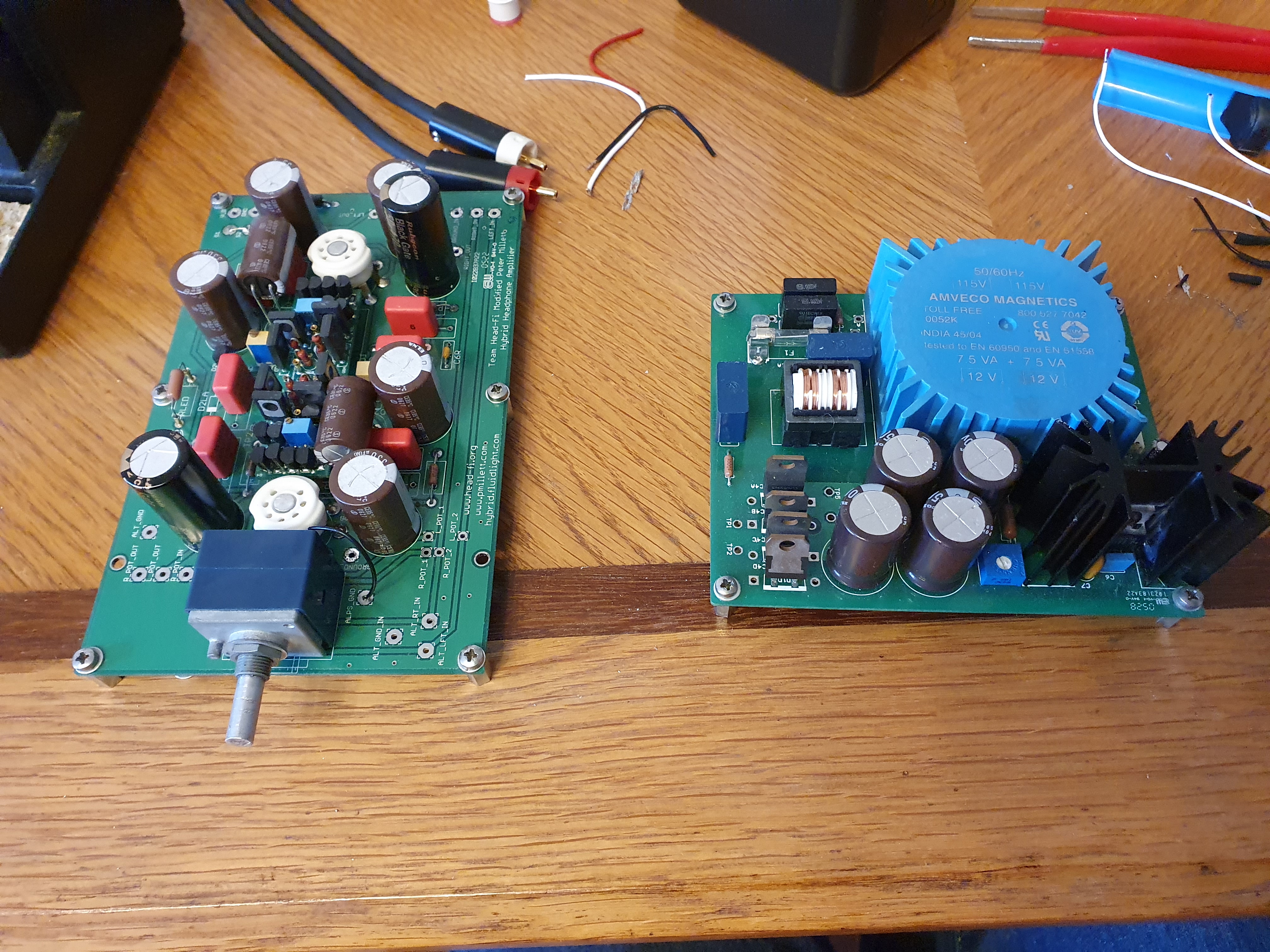
Refurbishing my old Pete Millett hibrid. The electrolitcs are over 15 years old, Should I replace them all or might they still be good? Building a new wood and aluminum case.
-
and now for something completely different part 3
MASantos replied to kevin gilmore's topic in Do It Yourself
Don't forget that a transformer shouldn't work near max output current. Most recommendations for Class A amplifier are to use something with at least double the output current capability. -
and now for something completely different part 3
MASantos replied to kevin gilmore's topic in Do It Yourself
That's quite a compact build, what is the size of that case? Looks good! What VA is that transformer? It looks quite big. -
I replaced the opamp and now it reads as the other 3. The offset still drifts around below 10mV. All other amplifiers I built (cfa, ckk3) with dc servos were very steady once the servos were installed. Is this drifting normal in the dynalo mini? I can't seem to find any solder bridges, it is as if the servos are not doing their job at all. Sound is now centered and similar in both SE and BAL ouputs, it is just the drifting that is puzzling me.
-
So I found a dead resistor in the R+ channel and replaced it. The L+ channel is the one acting up. I removed the servo jumpers and dialed the offset to less than 5mV on each channel. All fine. When I reinstalled the jumpers the L+ dc offset jumped to around 350mV while all the other channels remain below 2-3mV (but still wondering between 0 and 2-3mV, not ultra stable). The servo opamp for the L+ channel is getting power as it should. Might the IC be damaged and causing this? On further inspection, the 100k resistor next to the opamp measures 28K when soldered (I removed it and it measures 100k as it should) The opamp is measuring 1.1ohm between pins 2 and 3 (input + and input-) this is different from all the other opamps so I'm ordering a new one.